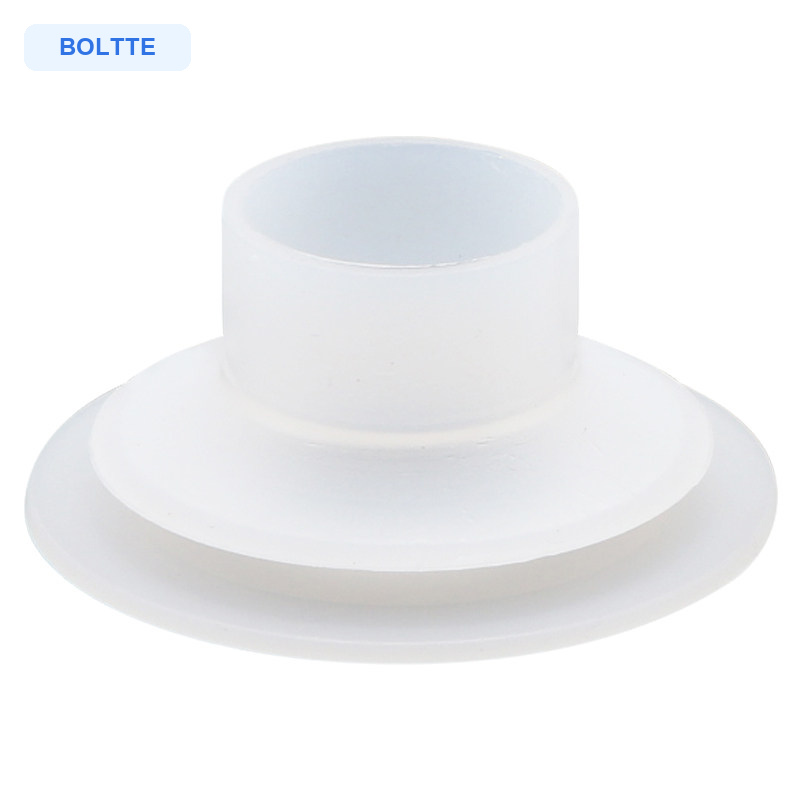
Down-filling equipment needs a vacuum contact point that fits the tooling, the pickup surface and the motion profile. A cup that looks close enough in a photograph can still create leakage, interference or inconsistent release if its opening, outside diameter or height is wrong. This guide explains how to select and validate the three current BOLTTE down-filling silicone vacuum cup options without assuming that a cup alone determines safe holding force.
What This Down-Filling Cup Family Includes
The current BOLTTE down-filling silicone vacuum cup family contains three selectable variants: a 60 mm A-Type, a 60 mm B-Type and an 84 mm version. All three use a flexible silicone body with a double-layer sealing profile. They are intended for down-filling machine tooling and compatible pneumatic vacuum-handling equipment.
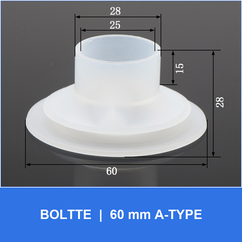
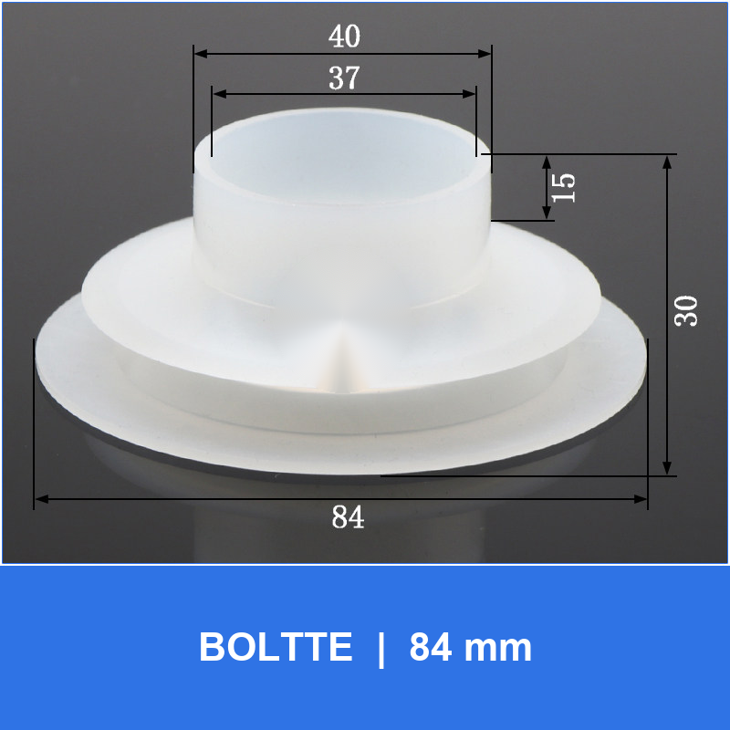
The sizes describe the cup family, but the ordering decision must be based on the full drawing. The 60 mm A-Type has a 25 mm inner opening and a 28 mm overall height. The 60 mm B-Type has a 30 mm inner opening and the same 28 mm overall height. The 84 mm cup has a 37 mm inner opening and a 30 mm overall height. These dimensions affect clearance, support and the interface with the existing tool.
Choose the Variant by Dimensions, Not Color or Appearance
Start with the machine drawing or a measured sample from the installed tool. If the station currently accepts a 60 mm cup, compare the required inner opening carefully: the A-Type and B-Type share the same outside size and height but have different 25 mm and 30 mm openings. That 5 mm difference can matter at the mounting interface. Do not treat the two 60 mm versions as interchangeable until the full connection geometry is confirmed.
The 84 mm version provides a larger nominal cup diameter, a 37 mm opening and a slightly taller 30 mm body. It may provide a larger contact footprint, but that does not automatically mean it is suitable for a heavier load. Available vacuum, leakage, acceleration, surface condition and machine safety factor all influence actual performance. Use the drawing to screen the fit, then confirm the result on the real machine.
Check the Workpiece and Tooling Before Installation
A double-layer profile can accommodate some contact variation, but it cannot correct every mismatch. Inspect the pickup surface for deep texture, holes, sharp edges, oil, dust or deformation that could prevent a stable seal. Confirm that the cup can contact a sufficiently continuous area without landing across a seam or unsupported edge. If the part flexes, test whether the contact area moves as vacuum is applied.
Also examine the surrounding tooling. Verify that the cup body does not collide with guides, filling heads, guards or adjacent cups through the full machine stroke. Allow space for the profile to compress without being pinched. The mating surface should support the cup evenly, and the vacuum passage must remain open. If the holder or fitting is unknown, review the vacuum cup holder and fitting guide before adapting the assembly.
Use a Repeatable Installation Checklist
Stop and isolate the machine according to the equipment manufacturer's procedure before working on the vacuum tool. Record the installed model and orientation, then remove the old cup without damaging the holder. Clean the mating surface and vacuum passage. Confirm that no fragments, sealant or debris remain inside the port. Compare the new part with the drawing and the removed part rather than relying only on the outer diameter.
Install the cup squarely and avoid twisting, stretching or cutting the silicone profile. Use only the fastening method specified by the complete tooling design. After installation, apply vacuum at low machine speed and observe whether the two layers compress evenly. A tilted cup, restricted passage or distorted lip should be corrected before production. Do not add improvised clamps, adhesives or lubricants unless the machine builder has approved them.
Set the Vacuum System for the Actual Application
The cup is one part of a complete pneumatic system. Confirm the available vacuum level at the cup during pickup, not only at the generator under no-flow conditions. Check tubing diameter, tube length, fittings, valves, filters and any shared manifold for restrictions or leakage. A long or undersized line can slow evacuation even when the final vacuum level appears acceptable.
Measure pickup and release time at the required cycle rate. If several cups share one circuit, test the effect of a leaking or uncovered cup. The control logic may need a vacuum switch, check valve or separate zone, depending on the machine risk assessment. For additional sizing context, use the holding-force and cup-diameter guide, while remembering that calculated values still require a suitable safety factor and physical validation.
Validate Pickup, Motion and Release in Production
Begin with representative workpieces, including expected variation in surface finish, flatness, temperature and cleanliness. Record evacuation time, achieved vacuum, pickup position and release time. Run the machine slowly first. Watch for partial sealing, excessive cup collapse, sliding, delayed pickup or a part that remains attached after the release command.
Then test the intended acceleration, deceleration and direction changes under controlled conditions. Repeat enough cycles to reveal intermittent leakage and heat buildup. Include the least favorable approved workpiece, not only a clean sample. If a vacuum sensor is used, set its threshold from measured stable operation and confirm how the machine reacts when the threshold is not reached. Never use an unverified cup setup for lifting people or for a load whose fall could enter an occupied area.
Document the Approved Setup and Plan Replacement
Once the process passes validation, record the exact variant, supplier SKU, drawing dimensions, vacuum threshold, cycle conditions and inspection limits. Keep the 60 mm A-Type and B-Type clearly separated because their inner openings differ. Operators should know what normal lip shape and compression look like and when to stop the machine for inspection.
Check the silicone body for cuts, hardening, permanent distortion, contamination and uneven wear. Replace a damaged cup before it causes unstable pickup; do not wait for a complete seal failure. Replacement frequency should be based on observed process conditions rather than a universal cycle count. If the workpiece, speed, tooling or vacuum circuit changes, repeat the validation instead of assuming the previous approval still applies.
Prepare the Information Needed for an Accurate Quote
For a repeat order, provide the full choice: 60 mm A-Type, 60 mm B-Type or 84 mm. For a new application, add a photo or drawing of the tooling, the contact surface, workpiece dimensions and mass, cycle rate, available vacuum, acceleration, temperature and quantity. Mention any surface variation, contamination or space limit that may affect sealing.
If the existing geometry does not match these three variants, use the BOLTTE vacuum application and custom quote form. Clear application data lets the supplier check dimensional compatibility and identify what still needs machine testing. The final selection should combine drawing confirmation, a controlled installation and documented production validation.