Choosing a vacuum cup is only part of a reliable handling system. The holder, fitting and mounting arrangement determine how the cup connects to the machine, how the vacuum line is routed and how the assembly responds to height variation or contact shock. A cup with the correct shape and material can still perform poorly when its holder thread, port direction, tube size or stroke is mismatched.
This guide explains a practical way to select vacuum cup holders, adapters and spring-loaded mounts for industrial pick-and-place equipment. Start with the cup and workpiece, then work outward toward the robot, fixture or machine frame.
Start with six interface questions
Before comparing model codes, record these six requirements:
- Cup connection: How does the elastomer cup attach to its nipple, adapter or holder?
- Machine mounting: Does the tool plate need a male thread, female thread, through-hole or locknut arrangement?
- Vacuum port: Should the hose enter from the top or the side?
- Tube or fitting: What tube outside diameter, threaded port or hose barb is used?
- Compliance: Is a rigid holder sufficient, or is vertical stroke or angular compensation needed?
- Environment: Are washdown, corrosion, temperature, oil, dust or restricted space important?
Do not select by mounting thread alone. Two holders may share an M14 machine thread but have different vacuum ports, cup connections, strokes or overall lengths.
Rigid holder or spring-loaded mount?
A rigid holder is compact and responds quickly when the machine presents every workpiece at a consistent height. It is usually the first option for well-controlled fixtures, short approach distances and parts that can tolerate the programmed contact force.
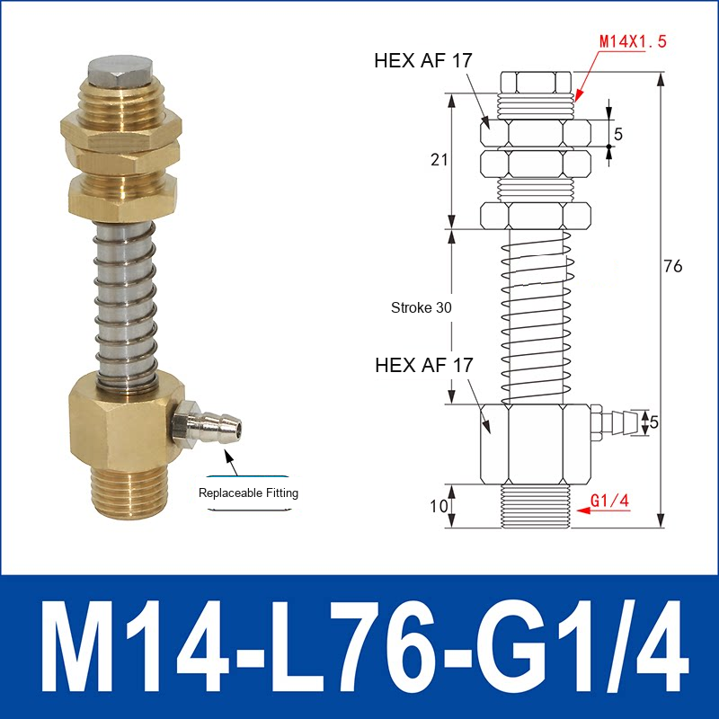
A spring-loaded holder adds vertical compliance. It can absorb small height differences, reduce impact during approach and help several cups make contact on a workpiece that is not perfectly level. It is especially useful when:
- stack height changes as sheets, cartons or components are removed;
- the robot or actuator has normal positioning tolerances;
- multiple cups must contact the same part;
- the workpiece is thin, sensitive or easily marked by excessive contact force;
- the cup needs a short compliant stroke before vacuum is established.
Spring travel is not a substitute for correct robot positioning. The available stroke must cover the expected height variation while leaving enough working travel to avoid bottoming out. Also check the compressed length, overall length and surrounding clearance in the end-of-arm tool.
Choose the vacuum port direction
Top-port holders keep the tubing aligned with the holder axis. They work well when there is enough vertical clearance and the hose can move without rubbing against the tool frame.
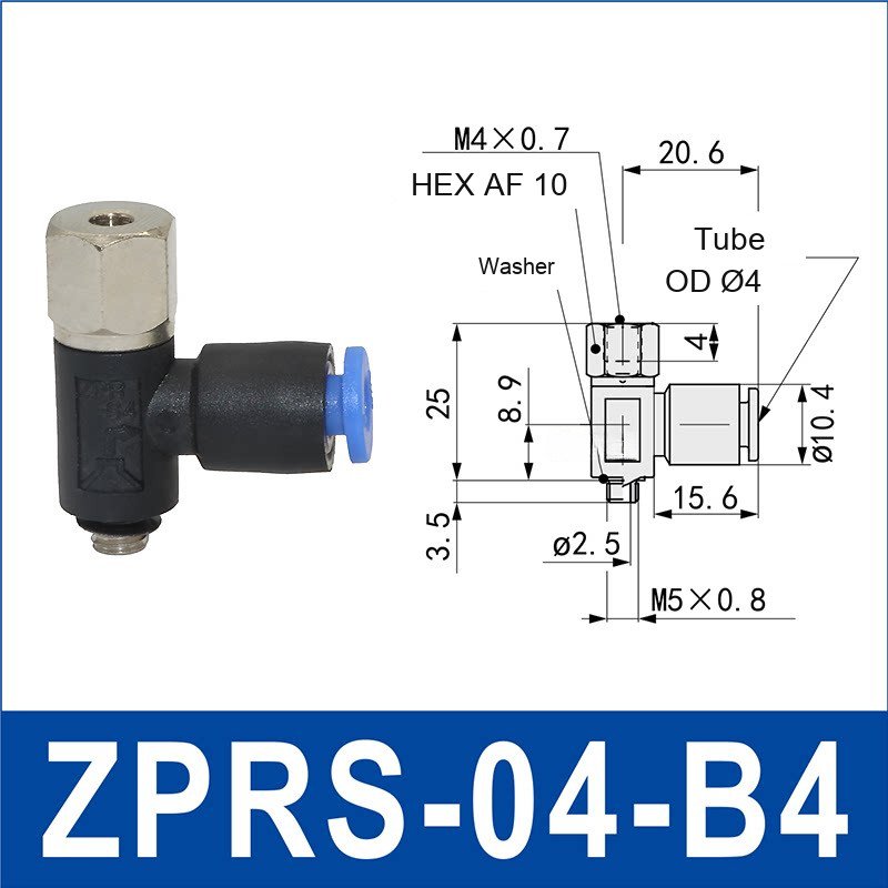
Side-port holders route tubing horizontally and can reduce the required height above the cup. They are useful in compact tooling, but the hose bend radius and moving clearance must be checked through the full machine stroke. The ZPRS/ZPRL side-port holders and ZPT adapters provide multiple tube and connection-code options, while the PAK side-port cup assemblies combine cup, mount and side vacuum port in one model family.
For larger cups with integrated spring travel, compare PJYS spring-loaded side-port assemblies, 60-80 mm.
Match the tube and fitting to the required flow
The vacuum line must move enough air to evacuate the cup and compensate for normal leakage. A line that is too restrictive can make pickup slow even when the final vacuum level is acceptable. Review:
- tube outside and inside diameter;
- tube length and the number of bends;
- push-in fitting, threaded fitting or hose-barb type;
- the number of cups sharing the same line;
- workpiece porosity and expected leakage;
- required cycle time.
Do not increase tube size without checking the generator and valve arrangement. Larger internal volume can also increase evacuation time. The correct design balances flow capacity, total system volume and cycle requirements.
When anti-rotation or angular compensation matters
An oval cup, directional cup or cup with an asymmetric support structure may need anti-rotation so its orientation stays fixed. Round cups usually tolerate rotation, but the tubing must still remain free of torsion.
Angular compensation is useful when the workpiece face is tilted or curved relative to the tool. It should be used only within the allowed angular range. Excessive misalignment can fold the cup lip, reduce the effective seal and create uneven wear.
Selection table
| Application condition | Holder feature to consider | What to verify |
|---|---|---|
| Consistent part height and compact tooling | Rigid holder | Approach position and contact force |
| Variable pickup height | Spring-loaded or height-compensating mount | Required stroke and compressed length |
| Limited space above the cup | Side vacuum port | Hose clearance and bend radius |
| Oval or directional cup | Anti-rotation feature | Orientation through the complete cycle |
| Tilted or uneven contact face | Angular compensator or compliant cup profile | Allowed angle and lip sealing |
| High leakage or short cycle | Low-restriction port and suitable tubing | Flow, total volume and pickup time |
A practical selection sequence
- Select the cup profile, material and diameter for the workpiece. Start with the vacuum cup selection guide if these are not yet defined.
- Confirm the cup-side connection and the tool-side mounting thread from drawings, not appearance.
- Choose top or side vacuum routing based on available space and hose motion.
- Decide whether rigid mounting, vertical stroke, anti-rotation or angular compliance is required.
- Check the tube size, total volume, expected leakage and cycle time.
- Review overall length, wrench flats, locknut position and installation access.
- Test pickup, transport and release on the real part at production acceleration.
Information to send with an RFQ
For faster model selection, include the cup model or cup connection, machine mounting thread, vacuum port preference, tube size, required stroke, workpiece material, surface condition, load, acceleration and cycle time. A photo or dimensioned drawing of the available mounting space is especially useful.
Upload your drawing or request a vacuum-cup recommendation. Final suitability must be verified on the actual machine and workpiece before production use.