Vacuum cup diameter is often selected from a load chart, but a sound selection starts with the pressure difference, effective sealing area, number of cups, direction of motion and a safety factor. This guide shows a practical calculation and explains why the final production test still matters.
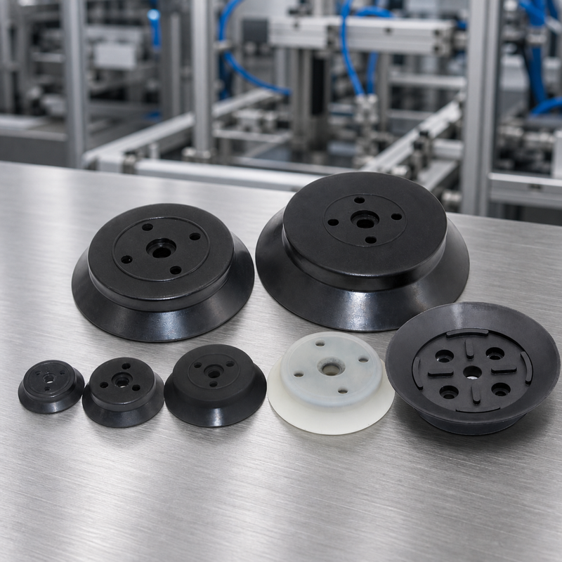
1. Start with the basic holding-force formula
For a cup sealed against a rigid, non-porous surface, the ideal normal holding force is:
Ftheoretical = Δp × A
- F is force in newtons (N).
- Δp is the pressure difference between atmosphere and the cup interior in pascals (Pa).
- A is the effective sealed area in square metres (m²).
For quick metric calculations, use F (N) = vacuum magnitude (kPa) × area (mm²) / 1000. For a circular cup, the nominal area is A = πD²/4. Catalog ratings may use an effective diameter smaller than the outside lip diameter, so use the manufacturer's rated force whenever it is available.
2. Worked example: a 40 mm cup at -60 kPa
- Nominal area = π × 40² / 4 = approximately 1,257 mm².
- Theoretical force = 60 × 1,257 / 1000 = approximately 75 N.
- 75 N is roughly 7.6 kgf, but it is not a safe payload rating.
- With a safety factor of 2.5, the preliminary usable normal force is about 30 N, before any further derating for leaks, acceleration, uneven load sharing or surface conditions.
This calculation is a screening tool. Flexible lips, textured workpieces, porous material, dust, oil and edge proximity can reduce the effective sealing area or prevent the target vacuum from being reached.
3. Apply a safety factor to the real load
The required force should include the workpiece mass, gravity, acceleration, deceleration, load direction and abnormal events such as an emergency stop. A simplified normal-lift estimate is:
Required force per cup = m × (g + a) × S / n
Here, m is workpiece mass, g is gravitational acceleration, a is the worst-case acceleration in the load direction, S is the safety factor and n is the number of cups that can reliably share the load. Do not assume perfect load sharing when the part bends or the cups are at different heights.
Many industrial projects begin with a safety factor of at least 2 for a horizontal pickup and a higher factor—often 4 or more—when the workpiece is handled vertically or loss of friction is possible. These are starting points, not universal rules. Follow the machine risk assessment, applicable standards and the component manufacturer's instructions.
4. Horizontal and vertical handling are different
When a cup is mounted above the workpiece, gravity normally acts along the cup axis and the pressure-difference calculation is the main starting point. When a cup grips a vertical wall, the load is parallel to the surface and resistance depends heavily on friction. Oil, dust, vibration and a low-friction material can sharply reduce the usable load even when the vacuum gauge looks stable.
For vertical handling, use verified friction data or conservative test results. Consider mechanical support, more cups, a larger diameter or a layout that prevents the workpiece from sliding.
5. Select the diameter from the required effective area
If the target normal force per cup and target vacuum are known, rearrange the equation:
Arequired = Frequired / Δp
Then calculate a starting circular diameter using D = √(4A/π). Round up to an available model and check that the complete sealing lip stays inside a stable surface area. A larger cup is not automatically better if it crosses an edge, sits on curvature, covers a hole or wrinkles thin material.
Worked example: from load to effective cup diameter
For illustration only, assume a rigid, non-porous 5 kg workpiece is lifted normal to its surface, with upward acceleration of 2 m/s², a chosen safety factor of 2.5, and four cups sharing the load equally.
Using g = 9.81 m/s², the required force is 5 × (9.81 + 2) × 2.5 / 4 ≈ 36.9 N per cup. At 60 kPa vacuum magnitude at each cup, the required effective area is 1000 × 36.9 / 60 ≈ 615 mm², giving an effective circular diameter of about 28.0 mm.
The safety factor is already included. This is not a recommendation for a nominal 28 mm cup: confirm rated force or effective area, actual load sharing and sealing, then validate the production cycle.
6. Check the complete pneumatic system
- Vacuum at the cup: measure during the real cycle, not only at the generator.
- Leakage and flow: porous or textured workpieces may need more flow rather than a higher nominal vacuum.
- Tubing and valves: long or restricted lines slow evacuation and release.
- Cup profile and material: geometry affects the seal; compound affects wear, temperature and oil compatibility.
- Mounting: spring compensators and ball joints can improve contact but may change installed height and motion.
7. Validate before production
Test normal and worst-case parts at production speed. Record vacuum build time, minimum vacuum during motion, release time, cup deflection and wear. Include contaminated, warped or textured samples where they can occur. Verify the response to a missed cup or vacuum loss and never use a basic catalog calculation as the sole safeguard for personnel or suspended loads.
Browse standard vacuum cups or send the workpiece weight, surface, motion profile, target vacuum, cup quantity and mounting details through the BOLTTE application RFQ for model selection support.