When a vacuum cup drops parts, seals inconsistently or takes too long to pick up, replacing the cup immediately may not solve the real problem. Leakage can come from the cup lip, fitting, hose, valve or workpiece. Weak grip can also be caused by insufficient cup area, low vacuum under load, acceleration, contamination or poor contact geometry.
This troubleshooting sequence helps separate cup problems from pneumatic, mounting and motion problems. Always follow the machine manufacturer's safety procedures. Isolate energy, vent stored vacuum and compressed air, and secure suspended loads before inspection.
Begin with the symptom, not the component
| Symptom | Common causes to check | First useful test |
|---|---|---|
| Vacuum builds slowly | Leakage, restricted hose, dirty filter or excessive system volume | Measure vacuum at the cup during the real cycle |
| Cup seals but cannot hold the load | Cup too small, low vacuum, high acceleration or low friction | Reduce motion and compare with the calculated holding requirement |
| Random dropped parts | Part variation, intermittent leak, hose movement or unstable contact | Log vacuum level and part position before each drop |
| Cup lip wears quickly | Angled approach, sliding contact, contamination or unsuitable material | Observe approach and release at reduced speed |
| Marks or deformation | Excess contact force, high vacuum, hard lip or wrong profile | Reduce approach force and test a more compliant setup |
| Slow or incomplete release | Trapped vacuum, long line, sticky surface or inadequate blow-off | Check release pressure and vacuum decay at the cup |
Step 1: inspect the cup lip and workpiece
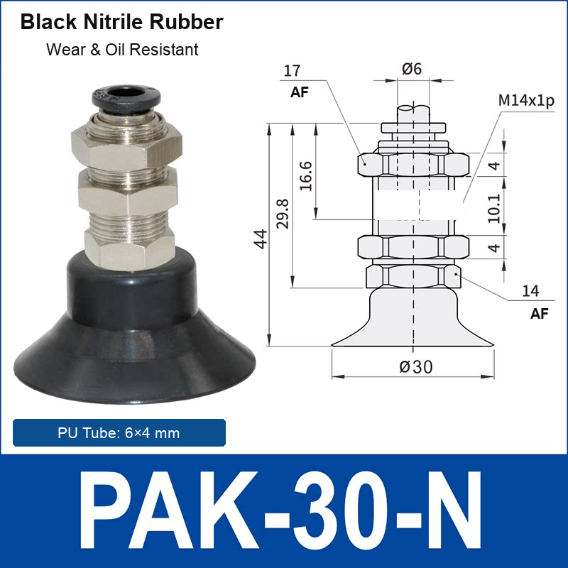
Clean the cup and the contact area with a method compatible with both materials. Look for cuts, permanent flattening, hardened rubber, swelling, embedded particles and uneven wear. A small defect at the sealing lip can create a large leak.
Also inspect the part itself. Surface texture, oil, dust, seams, labels, holes, curvature and protective film can change sealing behavior. If only certain parts fail, compare their contact area and position with successful parts.
Step 2: isolate leakage
Check each joint from the cup back toward the vacuum source:
- cup lip and cup-to-nipple connection;
- thread seal and adapter interface;
- push-in fitting or hose-barb connection;
- tube cuts, kinks, abrasion and bend stress;
- manifold plugs, valves and filters;
- generator or pump connection.
A static vacuum reading near the generator can look normal while the pressure at the cup collapses during pickup. Measure as close to the cup as practical and record the value while the workpiece is being accelerated, not only when the machine is stationary.
Step 3: check flow restrictions and total volume
If the system eventually reaches the required vacuum but misses the pickup time, inspect the hose diameter, hose length, elbows, filters, silencers and valve flow path. Multiple cups on one line increase the volume that must be evacuated. Porous materials and imperfectly covered cups add continuous leakage.
Do not assume that a larger tube always fixes the problem. The generator, valves and fittings must support the required flow, and additional internal volume can affect response. Test changes one at a time and compare pickup time at the cup.
Step 4: verify holding force under motion
Theoretical holding force is related to the pressure difference and effective sealing area, but real applications also include safety margin, acceleration, direction of load, friction and part variation. A cup may lift a stationary part during setup and still lose it during a fast horizontal move or emergency stop.
Use the vacuum cup holding-force and diameter guide to estimate the requirement, then validate on the actual machine. If the required force is too high, possible corrections include a larger cup, additional cups, a better contact location, reduced acceleration or a different handling method.
Step 5: review cup profile and material
A flat cup is generally stable on a smooth, rigid and relatively flat surface. Bellows add compliance for height variation or curved parts but also introduce more movement. Review the flat versus bellows guide when the cup rocks, folds or fails to contact consistently.
Material affects oil resistance, temperature behavior, wear, flexibility and marking risk. If a cup has hardened, swollen or become unusually soft, check whether the material is compatible with the process. The silicone versus NBR guide provides a starting comparison; actual formulations and operating limits must be confirmed for the selected model.

Step 6: observe approach, pickup and release
Run the machine slowly and watch the full sequence. The cup should approach the part squarely, make controlled contact, establish vacuum before lifting and release without being dragged across the surface. Common motion-related failure modes include:
- the cup hits the part at an angle;
- the spring mount reaches the end of its stroke;
- the part moves before vacuum reaches the required level;
- horizontal acceleration creates excessive shear;
- the cup slides during release and damages the lip;
- the hose pulls the cup or holder out of alignment.
A spring-loaded or height-compensating holder may help with normal part-height variation, but it cannot correct a large positioning error. Read the holder and spring-mount selection guide when contact height or hose routing is part of the problem.
Replace, redesign or keep testing?
Replace the cup when the lip is cracked, permanently deformed or materially degraded. Redesign the setup when failures follow a repeated pattern tied to part geometry, acceleration, mounting alignment or flow capacity. Continue controlled testing when the cause is uncertain, changing only one variable at a time and recording vacuum level, pickup time and failure point.
Troubleshooting information for an RFQ
Send the current cup and holder model, workpiece material, contact-surface photo, load, movement direction, acceleration, vacuum level measured at the cup, pickup time, tube size and a short video of the failure if available. This information is more useful than the statement “the cup does not hold.”
Upload application details or request a model review. Any recommendation must be validated under the actual load, motion, environment and machine safety requirements.