An end-of-arm tool is an assembly, not just a gripper. Mounting rods, brackets, connectors, fingers, hoses and cables all influence how it fits and moves. Choosing each item separately without a common layout can leave a tool that reaches the part but clashes with the machine or lacks a documented load review.
This guide focuses on the Robot Grippers & Fixtures category. It explains how to prepare a layout and select mounting components from BOLTTE's catalogue. It does not supply a payload rating for an assembled tool or imply that a component's pictured configuration has been validated on your robot.
1. Describe the workpiece and complete handling cycle
Begin with the part geometry, mass, pickup orientation and permitted contact areas. Record how the part is presented and where it must be placed. Explain variations such as changed dimensions, mixed parts or differing surface conditions. A tool designed around one ideal sample may not cover the normal production range.
Include the approach path, lifting direction, rotations, acceleration and release sequence for engineering review. Identify nearby guards, conveyors, fixtures and other tooling. Use a drawing of the cell and the end-of-arm arrangement rather than assuming that a static photograph demonstrates moving clearance. Any safety-related holding requirements need explicit evaluation by the responsible integrator.
2. Distinguish the gripper from its supporting fixture
A pneumatic gripper, a vacuum cup and a mounting connector perform different jobs. Choose the contact method for the part first, then develop a support structure that locates it correctly. A bracket that connects successfully does not prove that the gripper has enough usable force or that the robot can carry the complete assembly.
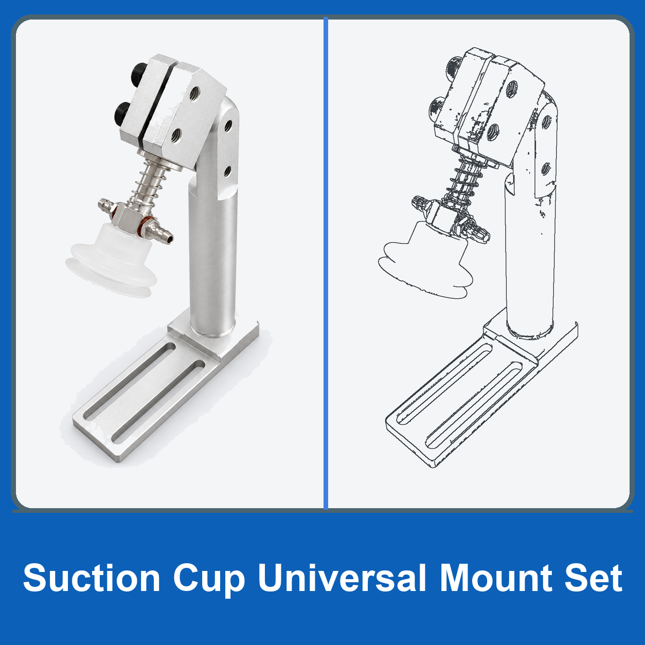
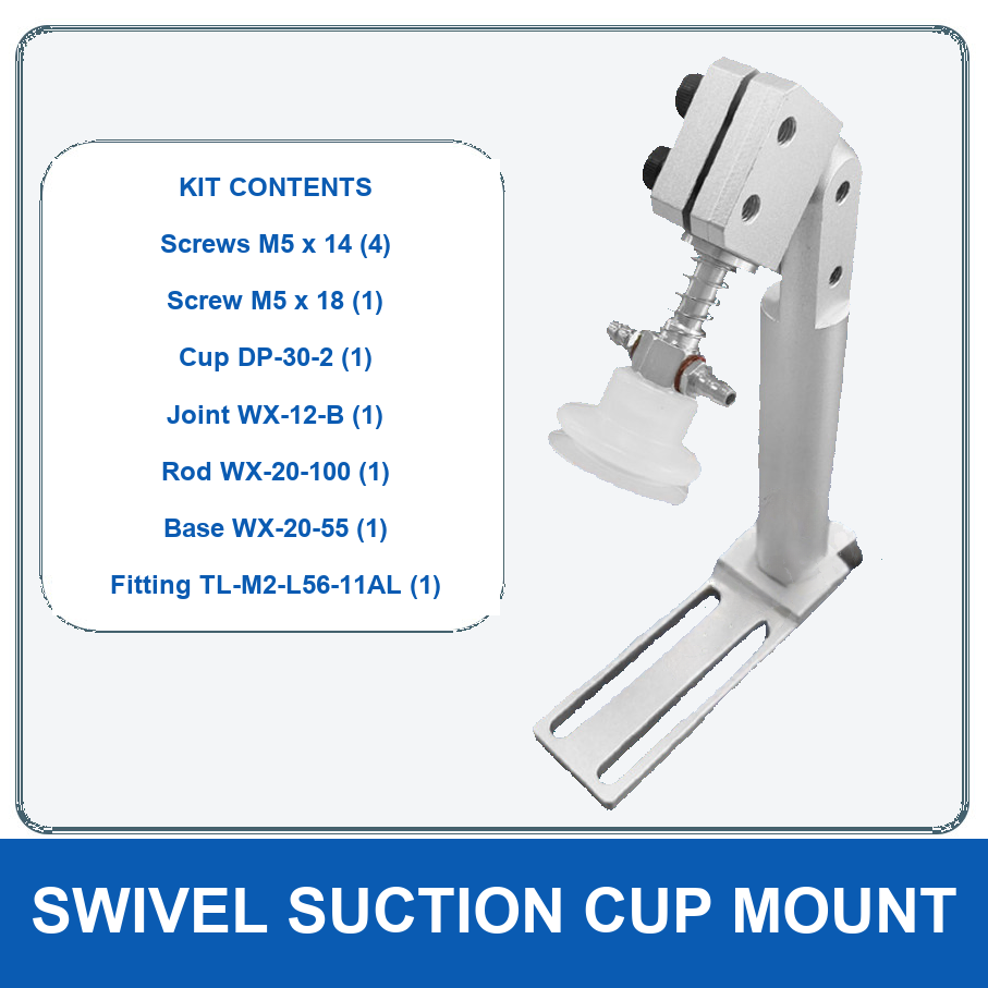
The BOLTTE fixture mounting range contains universal rods, sliding brackets, cylinder brackets, parallel and cross connectors, rotary blocks, rotary heads and mount sets. These model types are not interchangeable. Use each selected model's engineering drawing to identify what it supplies and how it attaches to the next component.
3. Match interfaces and adjustment ranges
Record the robot-side interface, rod or tube dimensions, clamping interfaces, mounting holes and the connection to the gripper. Check axial position, rotation and access to every locking fastener. Distinguish a complete mounting set from a single connector or replacement component when preparing the bill of materials.
If an adjustable component is required, define the intended position and available travel without assuming unlimited adjustment. Consider whether the selected arrangement can be locked and serviced in the available space. Use adjustable swivel arms and mounting bases only after checking their specific drawing and compatibility with the rest of the assembly.
4. Review fingers, contact location and load data
Document finger geometry and the distance from the gripper reference surface to the contact point. Obtain the selected gripper's data for the actual configuration, including stroke, force definition, permitted finger length and relevant loads. Do not apply another manufacturer's figures to a BOLTTE model merely because the construction looks similar.
A SCHUNK pneumatic gripper technical example illustrates how force definitions, finger length and permissible moments are specified separately. These are general selection considerations, not claimed ratings for BOLTTE hardware. Ask for missing data before deciding that a longer finger or more distant contact point is acceptable.
5. Include the complete tool in the robot review
Provide the robot integrator with the mass and geometry of the whole tool, including supports, fasteners, grippers, sensors, hoses and cables, together with the handled part. Identify the resulting centre of gravity and load arrangement for review against the robot manufacturer's requirements. Nominal part weight alone is not the complete end-of-arm load.
Plan pneumatic and electrical routes through every operating orientation. Prevent rubbing, pinching and excessive bending, using the component suppliers' limits. If a sensor is required, confirm its interface and logic with the control design. Do not assume that a pictured sensor, connector or control board is included with every mechanical model.
6. Commission the assembly progressively
Inspect the bill of materials and assembly against the approved drawing before powered operation. Confirm fastener procedures, clamp engagement, moving clearance and the location of contact surfaces. Use the integrator's guarded commissioning process, starting with controlled motion and progressing only after the defined checks pass.
Validate pickup, travel, placement and release on representative parts across the normal variation. Record any slipping, part damage, unexpected movement or hose interference. Verify monitoring and fault responses through the approved safety procedure. This guide does not provide a universal response to loss of air or power; that behaviour depends on the actual mechanism and machine design.
7. Prepare the drawing package and maintenance record
Send a dimensioned tool layout, component list, mating interfaces, gripper details, part data and motion requirements. State which items are already owned and which must be supplied. Include the requested documentation and identify unknown operating limits rather than leaving them as implicit assumptions.
For cup-mounted tooling, our holder and spring-loaded mount guide provides additional interface checks. Email BOLTTE your fixture drawing for component identification. Keep the final model list, assembly revision and inspection requirements with the machine so replacement parts can be ordered without rebuilding the original assumptions.
Common ordering question
Can one drawing be used for several tool positions?
Only when the approved layout identifies every position and the relevant differences. A repeated component may use a different rod length, rotation or contact orientation on another branch. Number the positions and link each to the bill of materials. Record the final adjustment settings after commissioning, with photographs as supplementary context. This helps maintenance distinguish an identical spare part from a differently adjusted assembly and makes it easier to verify a replacement without assuming that every gripper on the robot shares one mounting arrangement.