Slow pickup can originate in the tubing between a functioning generator and a correctly selected cup. Diagnose the pneumatic path before increasing the generator size. This guide focuses on dimensions, routing and measurements that distinguish hose volume from a restrictive connection.
1. Distinguish outside and inside diameter
Push-in fittings normally identify the tube outside diameter, while flow calculations need the inside diameter. Two tubes with the same outside diameter can have different bores because their wall thicknesses differ. Record both values and the tubing material.
Check the supplier's pressure and vacuum suitability, temperature limits and bend radius. A flexible tube that fits a connector is not necessarily resistant to collapse or abrasion in the intended vacuum circuit.
2. Understand the diameter trade-off
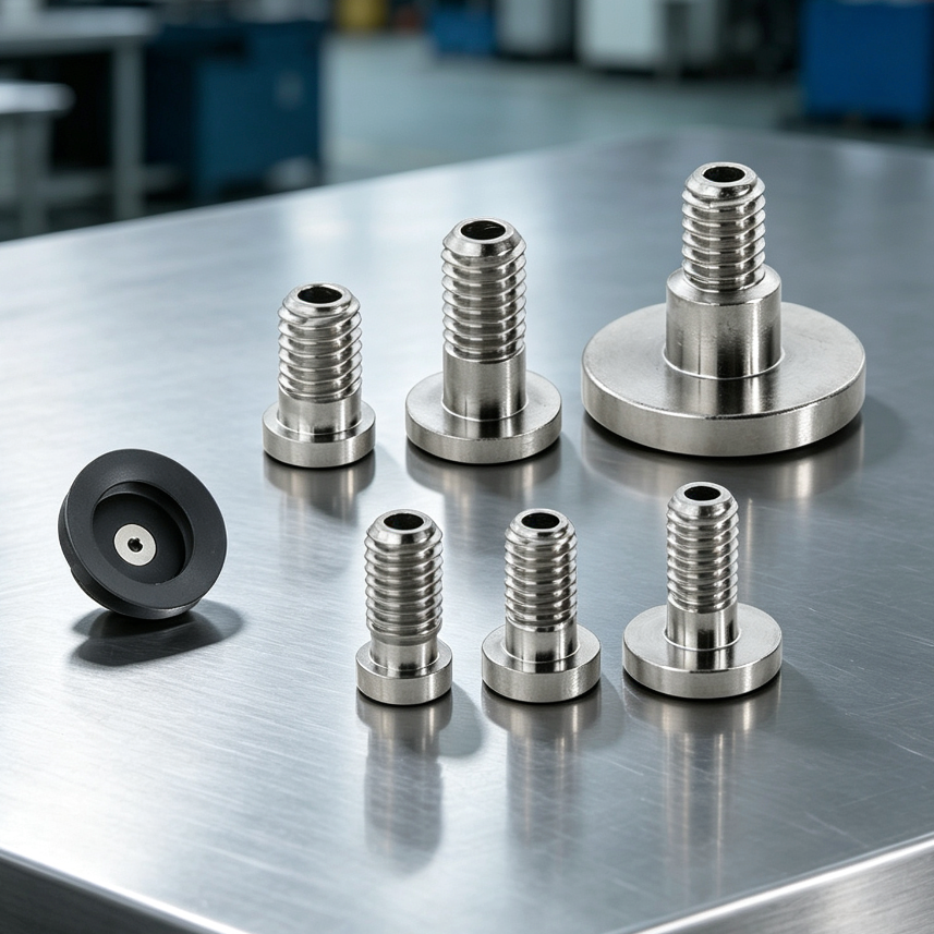
A larger bore can reduce flow restriction, but it also increases the volume that must be evacuated. There is no universally correct diameter without considering length, leakage and the source characteristic. Increasing every tube size may not shorten the cycle.
Estimate internal volume from the actual bore and length, then add fittings, reservoirs and cup cavities. Use consistent units; millimeters entered as meters create a large calculation error.
3. Map branches and small passages
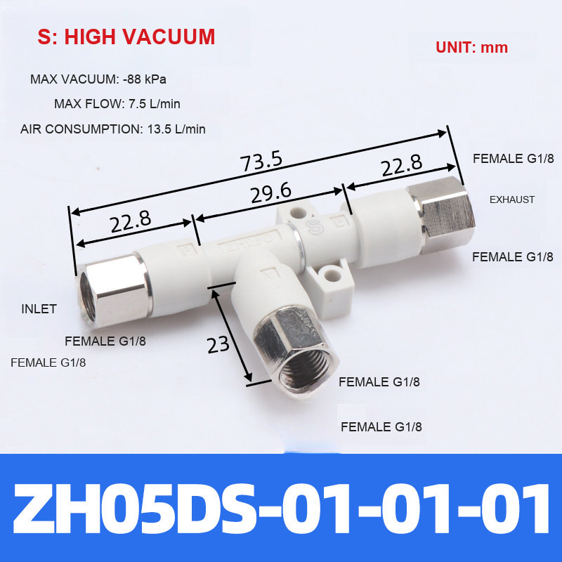
Include reducers, elbows, threaded adapters, filters and valves in the circuit sketch. Their smallest effective passage can dominate response even when the main tube looks generously sized. Do not estimate a fitting's internal passage from its outside appearance.
Identify which branches operate together. Separate cup groups may require different timing or isolation, but the controller and circuit must be reviewed before changing the branch arrangement.
4. Route for motion and service
Keep routing short where practical, with enough controlled allowance for the full motion envelope. Avoid pinching at fixture joints, pulling on push-in connections and rubbing against sharp edges. Verify the path at both ends of travel and during tool changes.
Label both ends of similar-looking lines. A maintenance replacement should reproduce the specified bore and material, not merely the visible color or outside diameter.
5. Measure at two useful locations
Measure vacuum near the source and near the cup using suitable instruments and the same cycle trigger. A delay or pressure difference between the locations points to a path issue, but does not alone identify which component is responsible.
Change one component at a time in a guarded test: shorten a line, remove an unnecessary reducer or replace a contaminated element according to the equipment procedure. Record the before-and-after trace.
6. Document the replacement specification
A usable tubing bill of materials includes outside diameter, inside diameter, material, length, connector standards and routing notes. Add the machine state in which the length was measured so a service technician does not cut a motion loop too short.
For a quotation, send the circuit drawing and target response time. If fitting passage data is missing, request it rather than assuming that a nominal thread size defines the usable flow area.
7. Related products and next steps
Vacuum fittings and adapters · Tube vacuum generators.
Send the complete model code, drawings or photographs, required quantity and application conditions to boltte@boltte.com. Confirm missing specifications in writing before ordering. Catalogue images illustrate the linked product family; they are not proof of compatibility, tested capacity or certification for your installation.
8. Further technical reading
These manufacturer references explain general engineering principles. Their product ratings, test results and installation values do not apply automatically to BOLTTE selections.