Rigid and flexible shaft couplings connect rotating components, but they solve different assembly problems. Start with shaft alignment, mounting conditions and the required motion accuracy before comparing outside diameters. A flexible element is not permission to ignore alignment or load limits.
1. Describe both connected shafts
Record each shaft diameter, tolerance, engagement length and any keyway or flat. Identify the motor and driven component, speed, torque duty and available axial space. State whether the shafts are supported independently.
Two equal nominal bore sizes do not describe the whole installation. A short shaft end or inaccessible fastener may rule out an otherwise plausible coupling.
2. Recognize the rigid connection
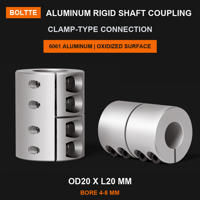
The linked aluminum rigid coupling is explicitly listed as not compensating for misalignment or vibration. Verify alignment and the machine's bearing arrangement before considering it. Do not treat a rigid sleeve as an equivalent replacement for an existing flexible assembly.
Its clamping construction still requires correct finished bores and installation instructions. A range of available bores is not a self-adjusting connection.
3. Define the flexible requirement
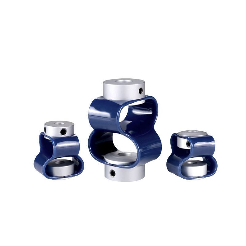
Flexible couplings can accommodate specified forms of misalignment within model limits. Request permissible angular, parallel and axial movement, plus the relevant torque and speed data. The word flexible does not define those values.
For positioning systems, ask about torsional behavior and the application's accuracy requirement. Do not infer zero backlash, encoder suitability or an allowable shaft offset from a photograph.
4. Check fastening and tool access
The GB range separates fastening orientations and requires D1 and D2 to be specified. Compare the selected drawing with the actual tool-access direction. Allow access without removing guards during normal operation.
Confirm shaft finish, engagement and any keyway requirements with the supplier. Tightening torque must come from the exact assembly instructions, not another coupling with the same outside diameter.
5. Commission against an aligned baseline
Isolate the drive before installation and retain the machine's guarding. Use the equipment's approved alignment and commissioning procedure, then observe vibration, noise and temperature under the permitted duty.
If symptoms appear, investigate alignment, fastening, bearing condition and load rather than automatically selecting a softer element. Document any shaft movement after the machine reaches its normal operating state.
6. Prepare a complete comparison
Send both shaft details, available envelope, mounting photographs and the required duty. Explain whether the goal is a replacement, a new design or correction of an existing vibration problem.
Keep the accepted coupling code, finished bore dimensions and installation requirements with the machine file. Review future replacements against those details instead of matching only the visible size or color.
7. Related products and next steps
Rigid shaft couplings · GB flexible shaft couplings.
Send the complete model code, drawings or photographs, required quantity and application conditions to boltte@boltte.com. Confirm missing specifications in writing before ordering. Catalogue images illustrate the linked product family; they are not proof of compatibility, tested capacity or certification for your installation.
8. Further technical reading
These manufacturer references explain general engineering principles. Their product ratings, test results and installation values do not apply automatically to BOLTTE selections.