An air manifold divides one compressed-air supply into several branches. Selecting it is not simply a matter of counting outlets: the connection method, tube dimensions, installation space and downstream demand must also agree. A manifold is a distribution component, not automatically a pressure regulator, shut-off valve or safety exhaust device. Plan those functions separately.
This guide uses BOLTTE's aluminum air manifold range as a practical ordering example. It explains which details to confirm before purchase and which checks belong to the complete machine. No pressure rating or flow capacity should be inferred from a photograph, body size or thread designation.
1. Start with the complete air circuit
Draw a simple circuit showing the inlet, manifold, valves, actuators and exhaust arrangements. Record which branches operate together and which remain idle. A machine that moves several grippers simultaneously can demand air differently from a machine that activates one branch at a time. Ask the machine designer to confirm the supply arrangement, isolation provisions and acceptable pressure variation at the point of use.
List the downstream devices and their required operating pressure and air quality from their own documentation. Do not select the manifold first and assume everything connected to it shares the same requirements. Separate incompatible circuits where necessary. Leave room for maintenance access and identify each branch so an operator can trace a fault without disconnecting unrelated lines.
2. Choose outlet count and supplied configuration
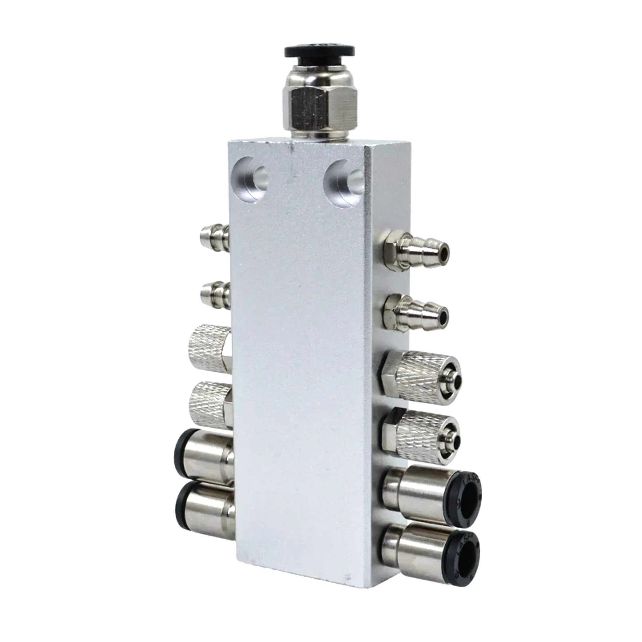
The BOLTTE aluminum pneumatic air manifold listing offers 4, 6, 8, 10, 12, 14, 16 and 20 outlet configurations. These are separate model selections. The product page also distinguishes bare bodies from configurations supplied with barbed, compression or push-in fittings.
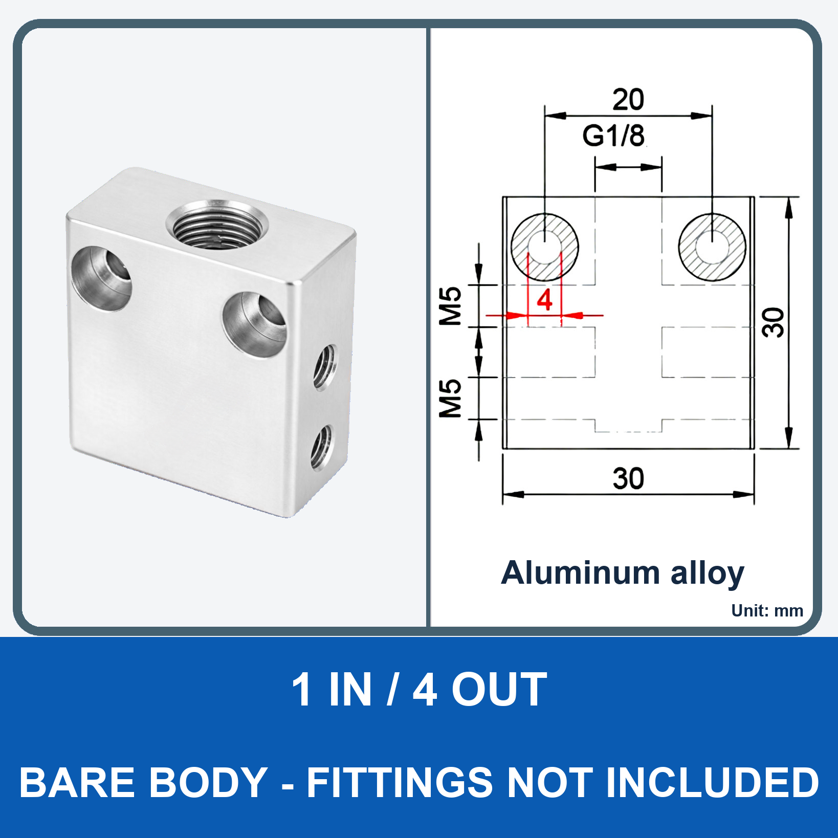
A bare body does not include fittings. A comparison photograph showing several fitting styles is not a promise that all those fittings arrive together. Read the full selected model label, then inspect its matching drawing. If you reserve an outlet for future equipment, specify a compatible closure arrangement; an unconnected opening is not a usable air branch until correctly sealed.
3. Match threads and tubing without guessing
The audited listing states a G1/8 manifold inlet and M5 side outlet threads. Its fitted options are specified for 6 mm tubing. These connection descriptions do not make every similarly sized connector interchangeable. Check the mating thread standard, sealing method, engagement and available wrench access against the selected drawing and fitting documentation.
For each branch, identify tube outside diameter, inside diameter and material. Confirm which measurement a fitting uses: a push-in connection and a hose barb may not use the same dimensional convention. Never force a connector that starts crooked or binds. When replacing a component, retain an accurate drawing or specification of both mating interfaces rather than relying on the outside appearance of the old fitting.
4. Review air preparation and delivery losses
Prepared air and sound connections are part of a dependable pneumatic system. Festo's compressed-air preparation guidance discusses contaminants and downstream distribution losses. This is a general engineering reference, not a certification of the BOLTTE manifold.
Ask for the minimum available inlet pressure during normal production and the permissible drop at the downstream device. Check restrictions from the complete route, including fittings, valves and tubing. A port designation alone is not a flow calculation. Likewise, fitting more outlets does not prove that every branch can run simultaneously without affecting the rest. If operating limits are absent from the listing, obtain them before installation rather than inventing a value.
5. Check mounting, routing and service access
Use the selected model drawing to check body dimensions, mounting positions and the space occupied by installed fittings. Leave room to insert or remove tubing, operate connector release collars where provided and use the required tools. Keep lines clear of sharp edges, hot surfaces and moving tooling, with the bend radius required by the tubing manufacturer.
Before assembly, isolate the system and verify that stored pneumatic energy has been released according to the machine procedure. Keep debris out of open ports and use only the seal or thread-treatment method approved for the connection. Do not let loose sealing material enter the air path. A damaged tube end, incorrect fitting or strained connection should be corrected, not hidden by additional tightening.
6. Validate with the real production sequence
Inspect the assembly first, then commission it through the machine's approved controlled procedure. Check for leakage, secure tubing and pressure behaviour when the intended branches operate together. Include pickup, hold, release and repeated cycling where relevant. The aim is to confirm the complete application, not simply to show that air emerges from each outlet.
Record the final connections, branch labels and measured operating conditions. If a device responds slowly, investigate supply pressure, downstream valves, restrictions and leakage before replacing the manifold. A satisfactory idle reading does not by itself explain what happens during a simultaneous production movement. Qualified personnel should decide the required acceptance checks and safety measures.
7. Prepare an unambiguous order or enquiry
Send the outlet count, bare or fitted configuration, inlet and outlet interface details, tube dimensions, available mounting space and operating requirements. Include the exact model label and a photo or dimensioned drawing of the mating installation. Distinguish the number of manifold bodies from the number of fittings or spare connectors required.
Need help identifying a connection? Email BOLTTE the circuit and dimensions. For the holder side of a vacuum installation, also read our vacuum cup holder and fitting guide. Final compatibility, operating limits and safe commissioning remain specific to the selected components and machine.