




ZW Vortex Tube Compressed-Air Spot Coolers, Small / Medium / Large
ZW Compressed-Air Vortex Tube Coolers
A vortex tube separates a compressed-air supply into a hot stream and a cold stream. The cold outlet provides local spot cooling without an electric motor or refrigerant circuit at the tube. Use it where a directed cold-air flow is useful around tooling, sensors, cameras or other accessible process areas. A suitable external compressed-air supply is required.
How It Works
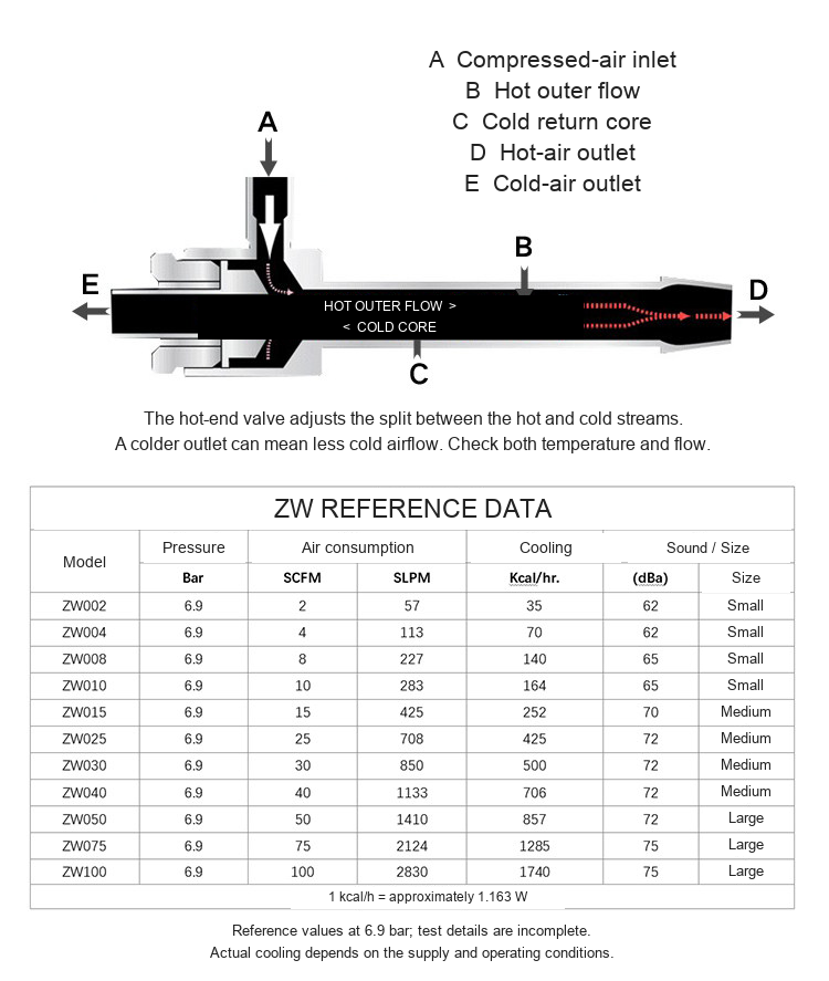
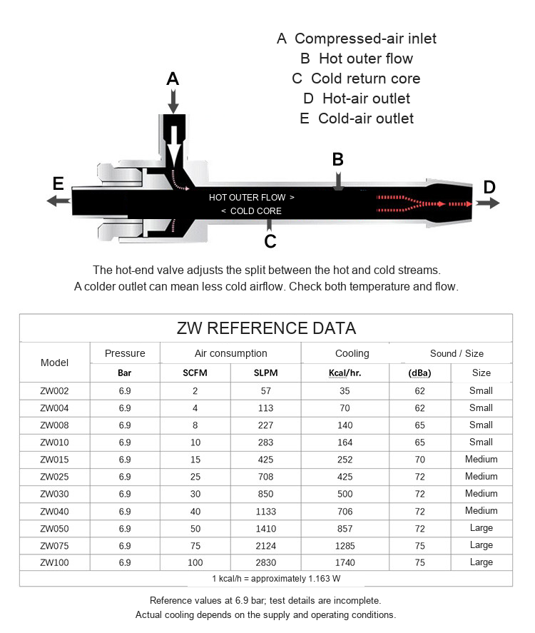
Compressed air enters the vortex chamber and forms a rotating stream. Part of the air travels toward the hot end; a returning inner stream exits at the cold outlet. The hot-end adjustment changes the division of hot and cold flow. A lower outlet temperature can reduce the amount of cold air delivered, so select and adjust for both temperature and the heat load.
Model Selection
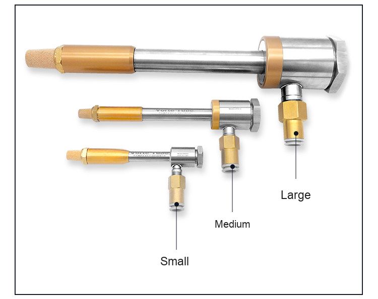
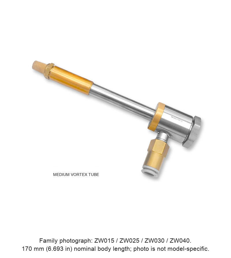
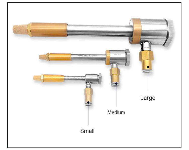
Select one of the 11 identified ZW models below. Small, medium and large photos are family reference views reused for the models within each size; they do not establish the exact model engraving. One selected vortex tube is offered per unit.
| Model | Size | Air (SCFM) | Air (SLPM) | Cooling (kcal/h) | Sound dB(A) |
|---|---|---|---|---|---|
| ZW002 | Small | 2 | 57 | 35 | 62 |
| ZW004 | Small | 4 | 113 | 70 | 62 |
| ZW008 | Small | 8 | 227 | 140 | 65 |
| ZW010 | Small | 10 | 283 | 164 | 65 |
| ZW015 | Medium | 15 | 425 | 252 | 70 |
| ZW025 | Medium | 25 | 708 | 425 | 72 |
| ZW030 | Medium | 30 | 850 | 500 | 72 |
| ZW040 | Medium | 40 | 1133 | 706 | 72 |
| ZW050 | Large | 50 | 1410 | 857 | 72 |
| ZW075 | Large | 75 | 2124 | 1285 | 75 |
| ZW100 | Large | 100 | 2830 | 1740 | 75 |
All figures above are supplier reference data stated at 6.9 bar (about 100 psi). Inlet temperature, cold fraction and noise-test distance were not specified. They are reference values, not a promise of installed output. 1 kcal/h is approximately 1.163 W; this is a power-unit conversion, not a temperature rating. Compressor delivery must support the selected flow at the actual inlet pressure. No blanket minimum temperature is promised.
Dimensions and Port References
| Size / models | Length / body diameter | Air inlet | Cold outlet |
|---|---|---|---|
| Small: ZW002/004/008/010 | 125 / 19 mm (4.921 / 0.748 in) | PT1/8 | PT1/4 |
| Medium: ZW015/025/030/040 | 170 / 30 mm (6.693 / 1.181 in); tube 12.7 mm (0.500 in) | PT1/4 | PT3/8 female |
| Large: ZW050/075/100 | 280 / 46 mm (11.024 / 1.811 in) | PT3/8 | G3/4 |
Dimensions come from the supplied family drawings. Inch values are calculated using 25.4 mm per inch. PT and G thread names are retained as supplied; do not assume NPT interchangeability. Check the exact outlet, thread and connector configuration before installation. Confirm the required body material before ordering; no certified alloy grade is stated for this family.
Applications Shown in the Original Photos
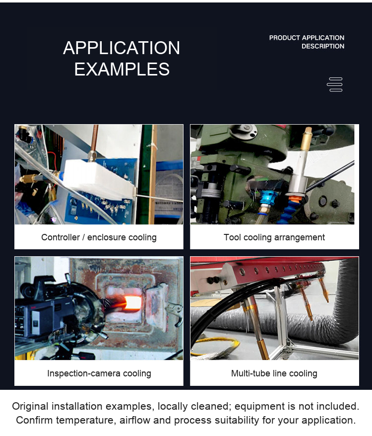
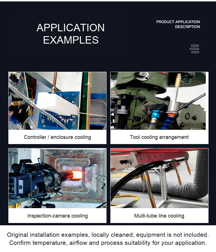
- Local cooling around a controller or equipment enclosure.
- Directed cold air near a machining tool.
- Cooling near an inspection camera or sensor in a hot area.
- Multiple tubes installed along a production line.
The photographs show possible arrangements. The actual process needs a heat-load and air-supply check; the machinery, workpieces and support equipment shown are not included. Manage hot exhaust so it does not heat nearby components. Check for condensation on cooled surfaces where moisture would affect the process.
Supply, Accessories and What to Confirm
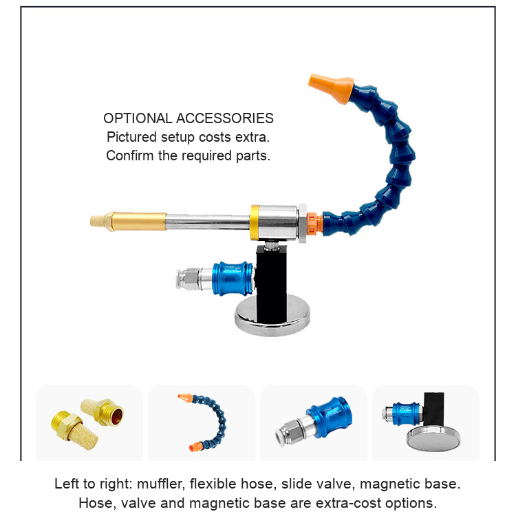
A hot-end muffler is listed as a standard accessory. The cold-end connector is not included by default. The pictured blue/orange flexible hose, manual slide valve and magnetic base are extra-cost optional accessories, not a complete kit included in the listed tube price. The PT1/4-to-10-mm fitting photograph is a family example and is not a fitting specification for every size.
Installation and Use
- Choose a model from the airflow and reference cooling table, then confirm available compressor flow and supply pressure.
- Provide a suitable clean, dry compressed-air supply with regulation and filtration appropriate to the process. Keep contamination out of the vortex tube.
- Mount the tube securely and route the cold outlet toward the intended cooling area. Keep the hot outlet clear and account for its temperature.
- Connect matching threads and fittings; confirm the missing cold-end connector and any optional directing hose before use.
- Introduce air in a controlled manner. Adjust the hot-end valve while measuring the useful outlet temperature and cold-air flow at the workpiece.
- Check real process temperatures, condensation, noise and air demand during operation. Isolate and depressurize before changing fittings or servicing.
Ordering Checklist
Specify model, size, supply pressure and available flow, target temperature or heat load, connection requirements, and any optional hose/valve/base. For a fit check, send an installation photo or drawing to boltte@boltte.com. No exact material grade, tested minimum temperature or model-specific performance beyond the supplied reference data is implied.
Original Product, Drawing and Application Images
Product photographs, dimension drawings, accessory views and installation examples are shown below. Dimensions include calculated inch references. The airflow picture is a conceptual illustration.





Modell / Konfiguration / SKU
| Modell / Konfiguration | SKU |
|---|---|
| ZW002 - Small | 4389982173587 |
| ZW004 - Small | 4389982173589 |
| ZW008 - Small | 4389982173590 |
| ZW010 - Small | 4389982173591 |
| ZW015 - Medium | 4389982173592 |
| ZW025 - Medium | 4389982173596 |
| ZW030 - Medium | 4951993854476 |
| ZW040 - Medium | 4951993854472 |
| ZW050 - Large | 4951993854475 |
| ZW075 - Large | 4951993854473 |
| ZW100 - Large | 4951993854474 |