


ZC Aluminum Compressed-Air Knives for Blow-Off, Drying and Cooling, 30-1550 mm
ZC Compressed-Air Knives for Surface Blow-Off
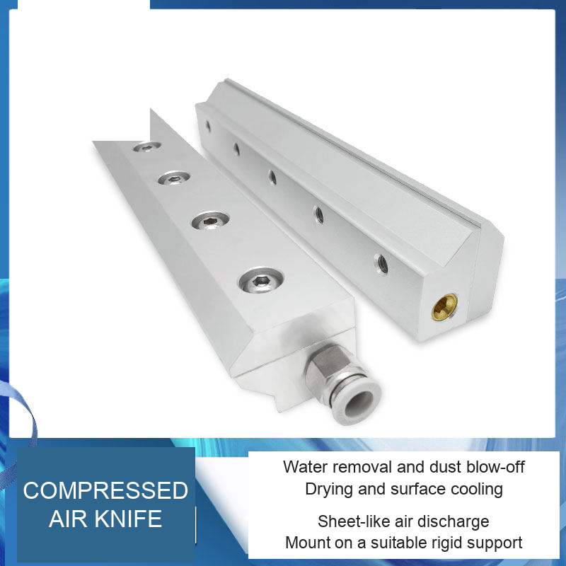
A ZC air knife converts a compressed-air supply into a thin, continuous sheet of air along its outlet. Position it across a working surface to sweep away water droplets, loose dust or debris, assist surface drying, or provide local air cooling. It is a pneumatic outlet, so a suitable external compressed-air supply is required.
What It Can Be Used For
| Task | How the air knife is used | Selection point |
|---|---|---|
| Water removal / surface drying | Sweep droplets from products, containers or moving workpieces after washing or filling. | Match knife length to the working width and test distance, angle and line speed. |
| Dust and loose-debris blow-off | Direct the air sheet across an accessible surface. | Check the material and provide suitable collection or extraction. |
| Local cooling | Pass moving air over an accessible component or process area. | Cooling depends on inlet-air temperature, flow and the actual heat load. |
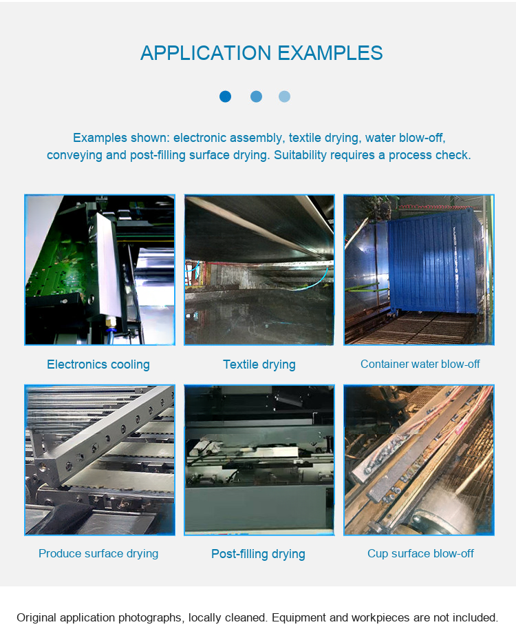
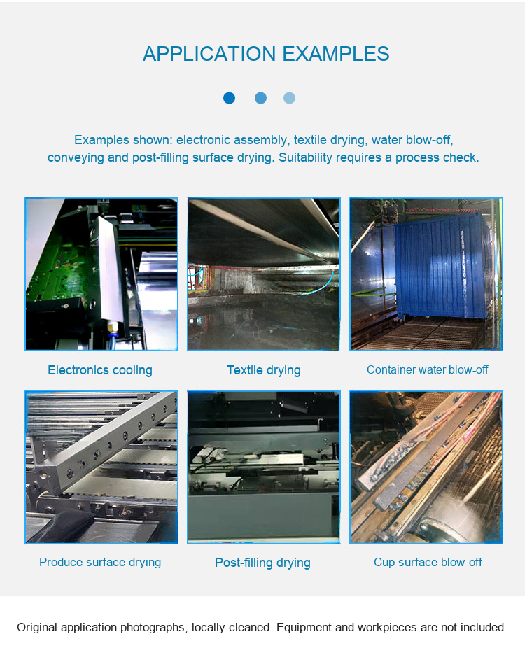
| Textile, produce and packaging lines | The original application photos show drying and cleaning arrangements on machinery. | Confirm air cleanliness and process compatibility for the actual workpiece. |
Models and Lengths
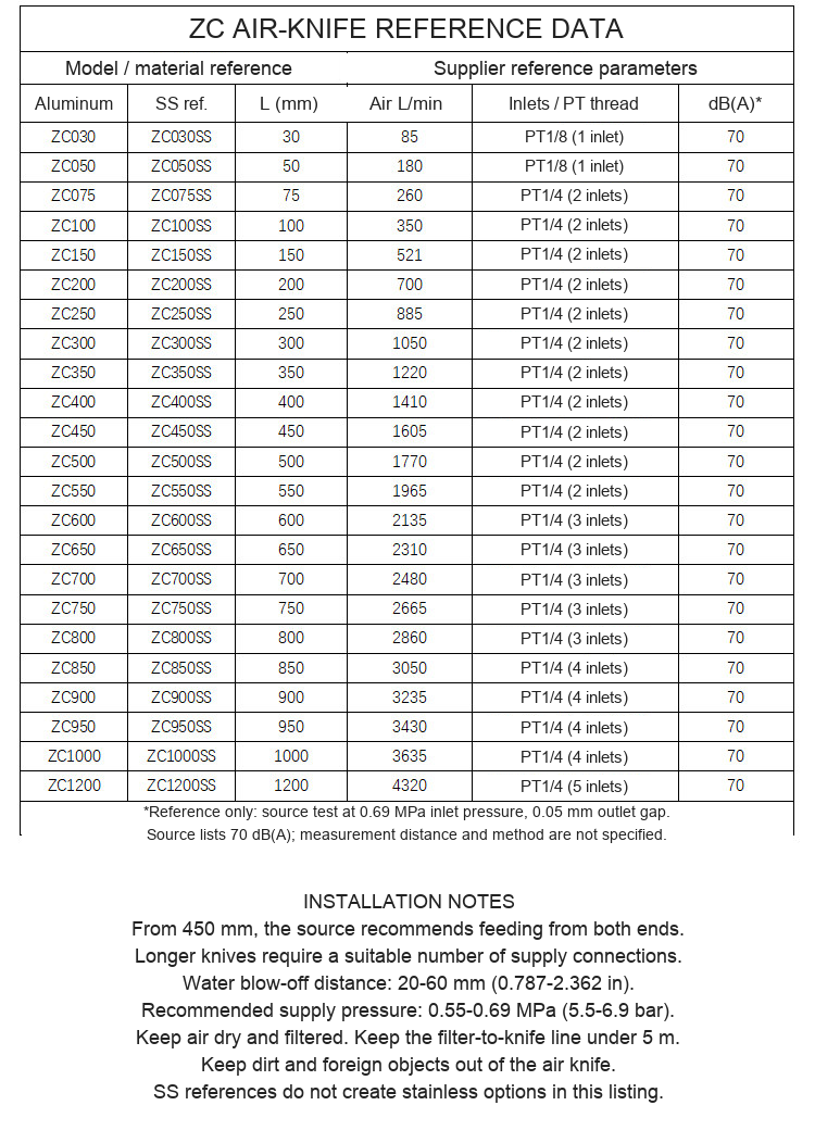
These selectable options are the aluminum ZC family listed in the supplied model table. Each order is one air knife in the selected nominal length. Photos show family examples and may show more than one view or length. Stainless-steel and PVC references in the supplier material are not selectable priced configurations here.
| Selectable model | Nominal length (mm) | Calculated length (in) |
|---|---|---|
| ZC30 | 30 | 1.181 |
| ZC50 | 50 | 1.969 |
| ZC75 | 75 | 2.953 |
| ZC100 | 100 | 3.937 |
| ZC150 | 150 | 5.906 |
| ZC200 | 200 | 7.874 |
| ZC250 | 250 | 9.843 |
| ZC300 | 300 | 11.811 |
| ZC350 | 350 | 13.780 |
| ZC400 | 400 | 15.748 |
| ZC450 | 450 | 17.717 |
| ZC500 | 500 | 19.685 |
| ZC550 | 550 | 21.654 |
| ZC600 | 600 | 23.622 |
| ZC650 | 650 | 25.591 |
| ZC700 | 700 | 27.559 |
| ZC750 | 750 | 29.528 |
| ZC800 | 800 | 31.496 |
| ZC850 | 850 | 33.465 |
| ZC900 | 900 | 35.433 |
| ZC950 | 950 | 37.402 |
| ZC1000 | 1000 | 39.370 |
| ZC1050 | 1050 | 41.339 |
| ZC1100 | 1100 | 43.307 |
| ZC1150 | 1150 | 45.276 |
| ZC1200 | 1200 | 47.244 |
| ZC1250 | 1250 | 49.213 |
| ZC1300 | 1300 | 51.181 |
| ZC1350 | 1350 | 53.150 |
| ZC1400 | 1400 | 55.118 |
| ZC1450 | 1450 | 57.087 |
| ZC1500 | 1500 | 59.055 |
| ZC1550 | 1550 | 61.024 |
Air Supply and Connections
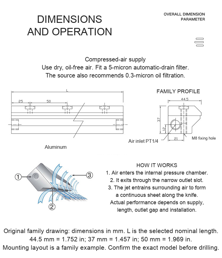
The source recommends dry, oil-free air, a 5-micron automatic-drain filter and, where required for oil removal, a 0.3-micron filter. Its stated operating supply range is 0.55-0.69 MPa (5.5-6.9 bar, approximately 80-100 psi). Check the compressor delivery at the knife while flowing air. Compressor tank pressure alone does not establish available flow. Air tubing is listed as a standard accessory; the exact tube length and fitting contents need confirmation.
Source examples list PT1/8 on 30/50 mm models and PT1/4 on the larger reference models. PT thread descriptions are retained as supplied and should not be substituted with NPT without checking fit. Longer knives need enough air inlets and line capacity to avoid uneven discharge. The source recommends feeding from both ends starting at 450 mm. The pictured PT1/4 to 10 mm fitting and M8 mounting detail are family examples.
Supplier Air-Consumption Reference
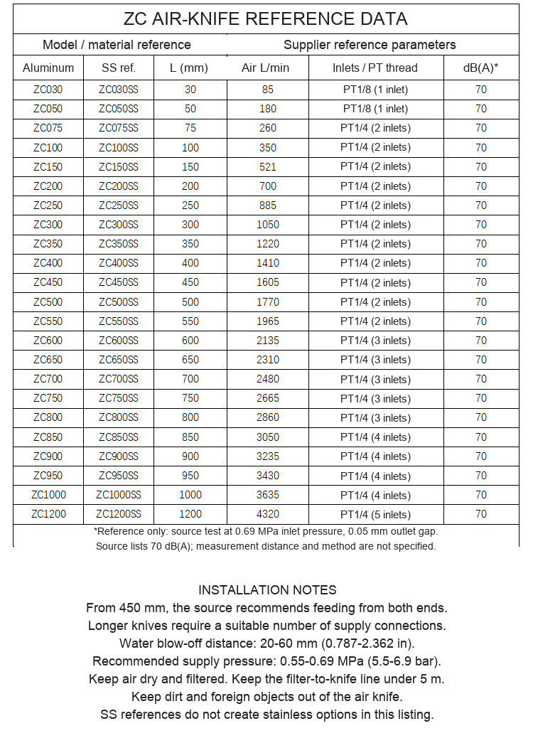
The following supplied values were stated at 0.69 MPa inlet pressure and a 0.05 mm outlet gap. They are reference data, not a guarantee at every installation. No flow value is extrapolated for the additional priced lengths absent from the table.
| Length (mm) | Air consumption (L/min) | PT inlet reference |
|---|---|---|
| 30 | 85 | PT1/8, 1 inlet |
| 50 | 180 | PT1/8, 1 inlet |
| 75 | 260 | PT1/4, 2 inlets |
| 100 | 350 | PT1/4, 2 inlets |
| 150 | 521 | PT1/4, 2 inlets |
| 200 | 700 | PT1/4, 2 inlets |
| 250 | 885 | PT1/4, 2 inlets |
| 300 | 1050 | PT1/4, 2 inlets |
| 350 | 1220 | PT1/4, 2 inlets |
| 400 | 1410 | PT1/4, 2 inlets |
| 450 | 1605 | PT1/4, 2 inlets |
| 500 | 1770 | PT1/4, 2 inlets |
| 550 | 1965 | PT1/4, 2 inlets |
| 600 | 2135 | PT1/4, 3 inlets |
| 650 | 2310 | PT1/4, 3 inlets |
| 700 | 2480 | PT1/4, 3 inlets |
| 750 | 2665 | PT1/4, 3 inlets |
| 800 | 2860 | PT1/4, 3 inlets |
| 850 | 3050 | PT1/4, 4 inlets |
| 900 | 3235 | PT1/4, 4 inlets |
| 950 | 3430 | PT1/4, 4 inlets |
| 1000 | 3635 | PT1/4, 4 inlets |
| 1200 | 4320 | PT1/4, 5 inlets |
The source table lists 70 dB(A), but gives no measurement distance or noise-test method. Actual sound level depends on supply and installation. The original family profile shows 44.5 x 37 mm (1.752 x 1.457 in), PT1/4 and M8 references. Confirm the exact length-specific drilling and inlet pattern before manufacture or installation.
Installation and Adjustment
- Select a nominal knife length that covers the required working width. Check the available space, supports and inlet routing.
- Mount the body on a rigid support without distorting the outlet. Keep fittings and the discharge slot free of foreign material.
- Install a suitable regulator and filters. The supplier recommends keeping the filter-to-knife air line within 5 m.
- For water blow-off, the source suggests an initial outlet-to-workpiece distance of 20-60 mm (0.787-2.362 in). Adjust the angle and distance on the real process.
- Start with a controlled supply and check air distribution along the full length. Increase supply capacity or use additional inlets as required for the selected model.
- Check drying/cleaning results at the intended production speed. Isolate and depressurize the air line before maintenance.
Before Ordering
Confirm nominal length, material, thread compatibility, mounting-hole layout, air consumption and the workpiece/process. Send the working width, available inlet pressure and flow, and a photo or drawing of the installation to boltte@boltte.com for a fit check. Other materials, lengths or joined arrangements need separate confirmation. A compressor, regulator, filter, installation equipment and the machinery shown in application photos are not specified as included.
Original Product, Drawing and Application Images
The views below retain the original product photography and technical lines, with English wording and inch conversions where useful. Air-sheet illustrations explain flow direction. The six original application photographs show example installations, not promised performance for every process.