
VHK2 / VHK3 Manual Pneumatic Shut-Off Valves
VHK2 / VHK3 Manual Pneumatic Shut-Off Valves
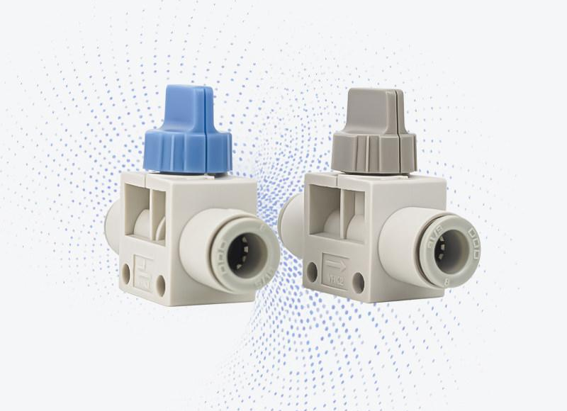
Manual air shut-off valves with a rotary handle for pneumatic tubing systems. Choose the exact model from the selector to view its corresponding product image and connection details.
Available Models
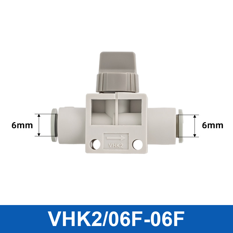
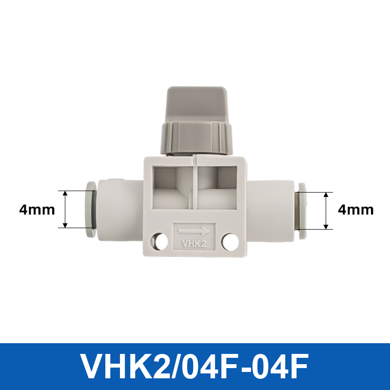
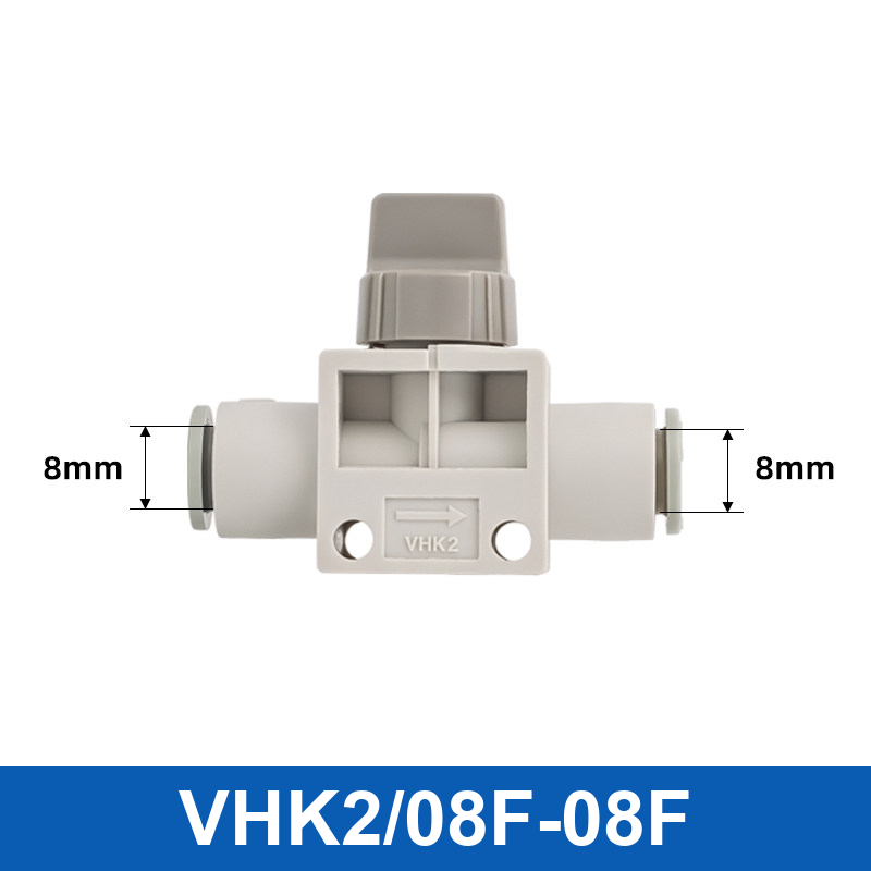
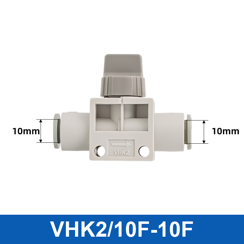
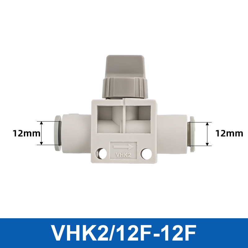
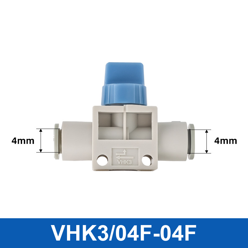
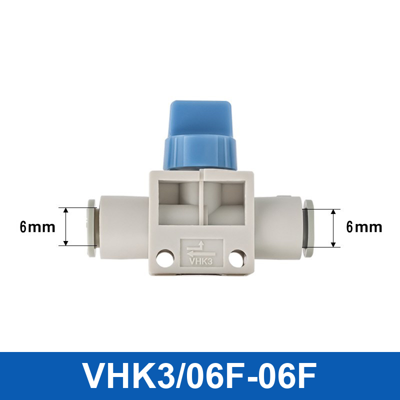
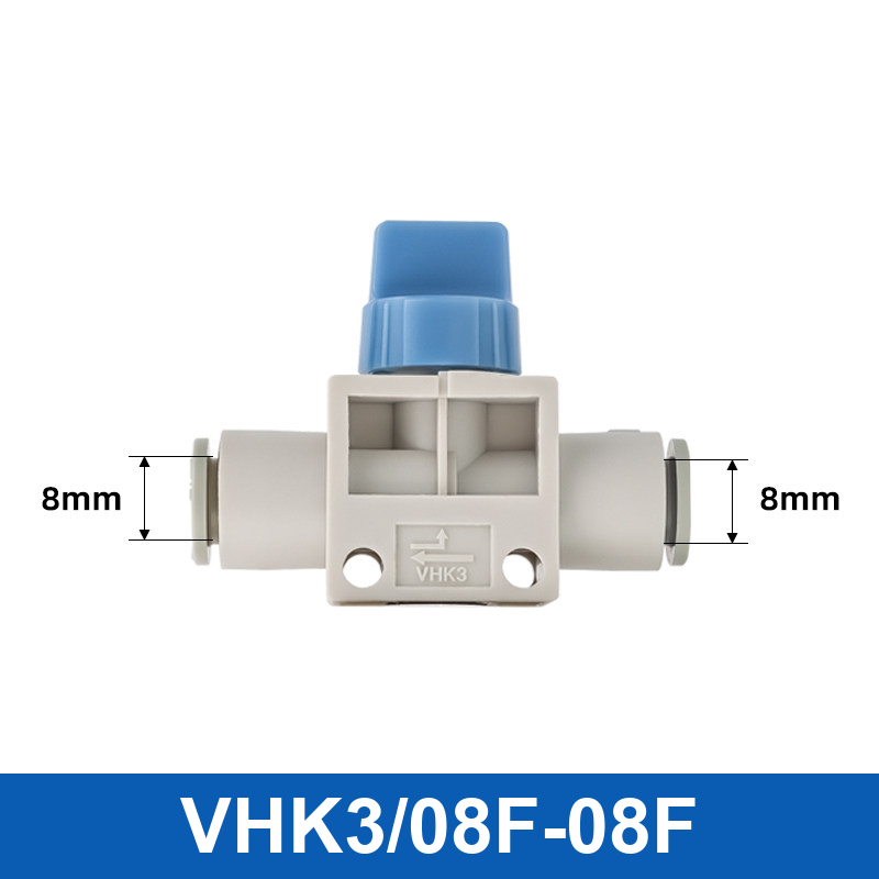
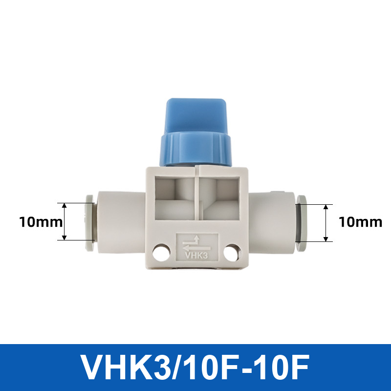
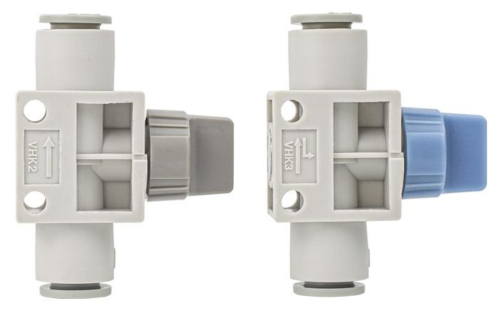
- VHK2 and VHK3 tube-to-tube configurations: 4, 6, 8, 10 and 12 mm tube outside diameter, as marked on the model image.
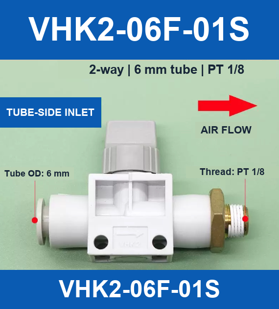
- VHK2-06F-01S: 2-way tube-side inlet configuration with a 6 mm tube connection and PT 1/8 threaded connection, as marked in the source image.
Selection and Installation
Check the model code, tube outside diameter, port configuration and marked flow direction before ordering. The body material is listed as plastic in the supplied product attributes. Confirm compatibility with your operating pressure, temperature and medium before installation; no unsupported ratings are specified here.
VHK Manual Shut-Off Valves
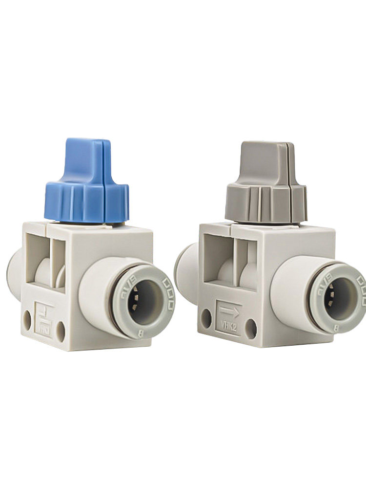
Quick installation, high-quality resin construction and good sealing. The manual rotary handle provides a clear indication of the valve position.
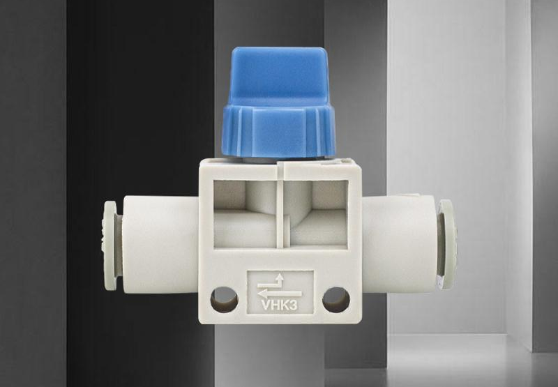
Durable Construction and Airtight Sealing
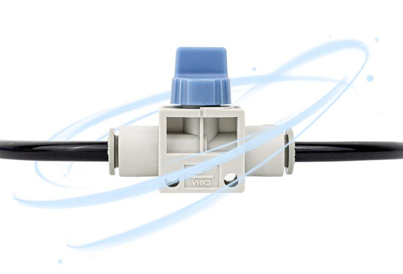
Easy Tube Connection
Push-in tube connections simplify pneumatic tubing installation. Select the correct outside diameter and connection configuration for your application.
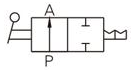
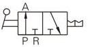
Two-Way and Three-Way Circuit Symbols
Opening, Closing and Exhaust Function
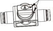
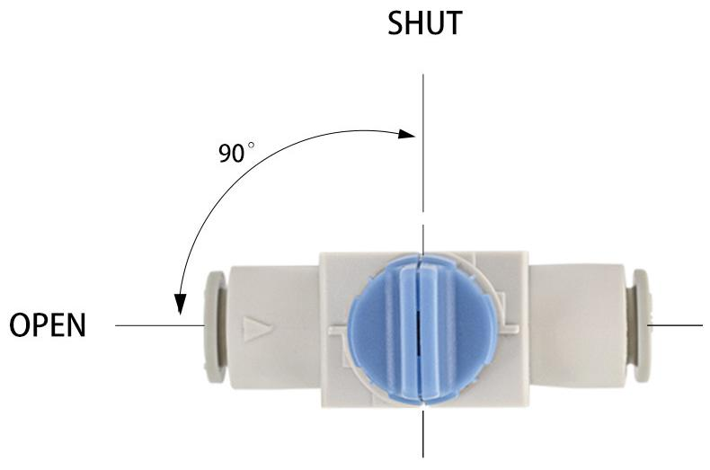
Closed: the handle arrow is at 90° to the arrow on the body.
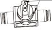
Open: the handle arrow aligns with the arrow on the body.
When the three-way version is closed, the outlet side exhausts to release pressure for adjustment and maintenance. Isolate the supply and verify that pressure has been fully released before servicing.
VHK Product Parameters
| Parameter | VHK source specification |
|---|---|
| Valve type | 2-port / 3-port valve |
| Working medium | Air |
| Proof test pressure | 1.5 MPa |
| Maximum operating pressure | 1.0 MPa (see Note 1) |
| Vacuum pressure | −100 kPa; use VHK2 (two-way) for vacuum applications |
| Ambient and fluid temperature | 0 to 60 °C |
| Compatible tubing | Nylon, soft nylon and polyurethane (see Note 2) |
| Optional accessory | Mounting bracket |
Note 1: When used at low pressure below 0.1 MPa, leakage may exceed the stated specification of 5 cm³/min. Take this into account before use.
Note 2: Observe the maximum operating pressure of soft nylon and polyurethane tubing. Refer to the applicable pneumatic tubing and fitting specifications. The original refers to an external catalog (No. 6), which is not included in the supplied image.
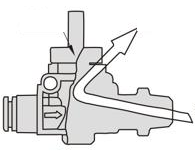
90° Rotary Operation
The direction of the knob clearly indicates whether the valve is open or closed. Turn counterclockwise from SHUT to OPEN as illustrated.
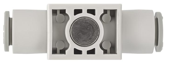
Seat Valve Structure and Sealing
Additional Source Reference: PHV Series
Important: The supplied long image also contains PHV-series reference specifications, drawings and a parts table. These are preserved below as source reference only. They are not verified dimensions or ratings for the VHK2/VHK3 sale models. In particular, the reference temperature range (−20 to 70 °C) differs from the VHK table above (0 to 60 °C). Confirm the selected model before using these reference values.
| Parameter | Additional reference value |
|---|---|
| Operating pressure | 0–10 kgf/cm² (0–1.0 MPa), as printed |
| Vacuum | −750 mmHg (10 Torr), as printed in the source |
| Proof pressure | 1.5 MPa |
| Operating temperature | −20 to 70 °C |
| Suitable tubing | Nylon tubing or PU tubing |
| Colors listed | Gray / black |
The vacuum figures above are reproduced as written; their gauge/absolute-pressure basis is not clarified in the source. Do not treat them as an independently verified conversion.
PHV Reference External Dimensions
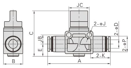
| Model | ØD | A | B | C | ØP | K | E | ØJ | JB | JC | Weight (g) |
|---|---|---|---|---|---|---|---|---|---|---|---|
| PHV6□ | 6 | 51.5 | 17 | 40.5 | 12.5 | 16.5 | 10 | 4.3 | 8 | 18 | 14.3 |
| PHV8□ | 8 | 58.5 | 18 | 42.5 | 15 | 18.5 | 11.5 | 4.3 | 8.5 | 19 | 17.5 |
| PHV10□ | 10 | 66 | 21 | 42 | 18 | 21 | 11 | 4.3 | 11 | 24 | 25.1 |
| PHV12□ | 12 | 71 | 22 | 46 | 21 | 23 | 13 | 4.3 | 11 | 24 | 31.4 |
Source note: □ stands for A or B. A = three-way; B = two-way. The two configurations have the same external dimensions in this PHV reference table.
Reference Internal Structure and Main Component Materials
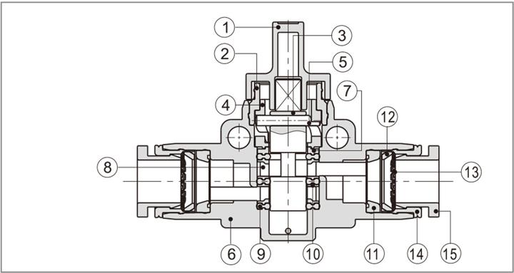
| No. | Component | Material |
|---|---|---|
| 1 | Knob | POM |
| 2 | Retaining ring | Aluminum alloy |
| 3 | Shaft | Aluminum alloy |
| 4 | Cam-groove block | POM |
| 5 | Pin | Stainless steel |
| 6 | Plastic body | PBT |
| 7 | Positioning block | Aluminum alloy |
| 8 | Spacer sleeve | POM |
| 9 | Profiled sealing ring | NBR |
| 10 | Spacer ring | Aluminum alloy |
| 11 | Profiled sealing ring | NBR |
| 12 | Positioning seat | POM |
| 13 | Spring washer | Stainless steel |
| 14 | Positioning ring | Aluminum alloy |
| 15 | Plastic connection port | POM |
Product Photographs
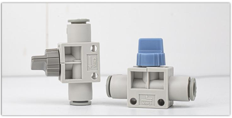
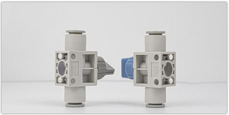
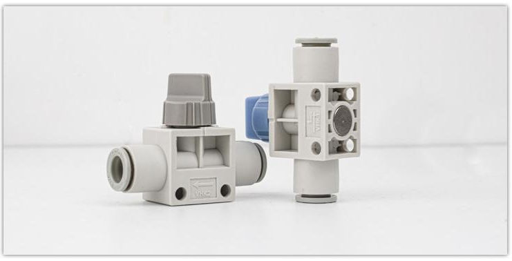
Modell / Konfiguration / SKU
| Modell / Konfiguration | SKU |
|---|---|
| VHK2/04F-04F | 5225104195161 |
| VHK2/06F-06F | 5225104195162 |
| VHK2/08F-08F | 5225104195163 |
| VHK2/10F-10F | 5225104195164 |
| VHK2/12F-12F | 5225104195165 |
| VHK3/04F-04F | 5225104195166 |
| VHK3/06F-06F | 5225104195167 |
| VHK3/08F-08F | 5225104195168 |
| VHK3/10F-10F | 5225104195169 |
| VHK3/12F-12F | 5225104195170 |
| VHK2-06F-01S | 6119305376738 |