




RTK-VT Vortex Tubes and Accessories, Stainless / Aluminum
RTK-VT Compressed-Air Vortex Tubes and Accessories
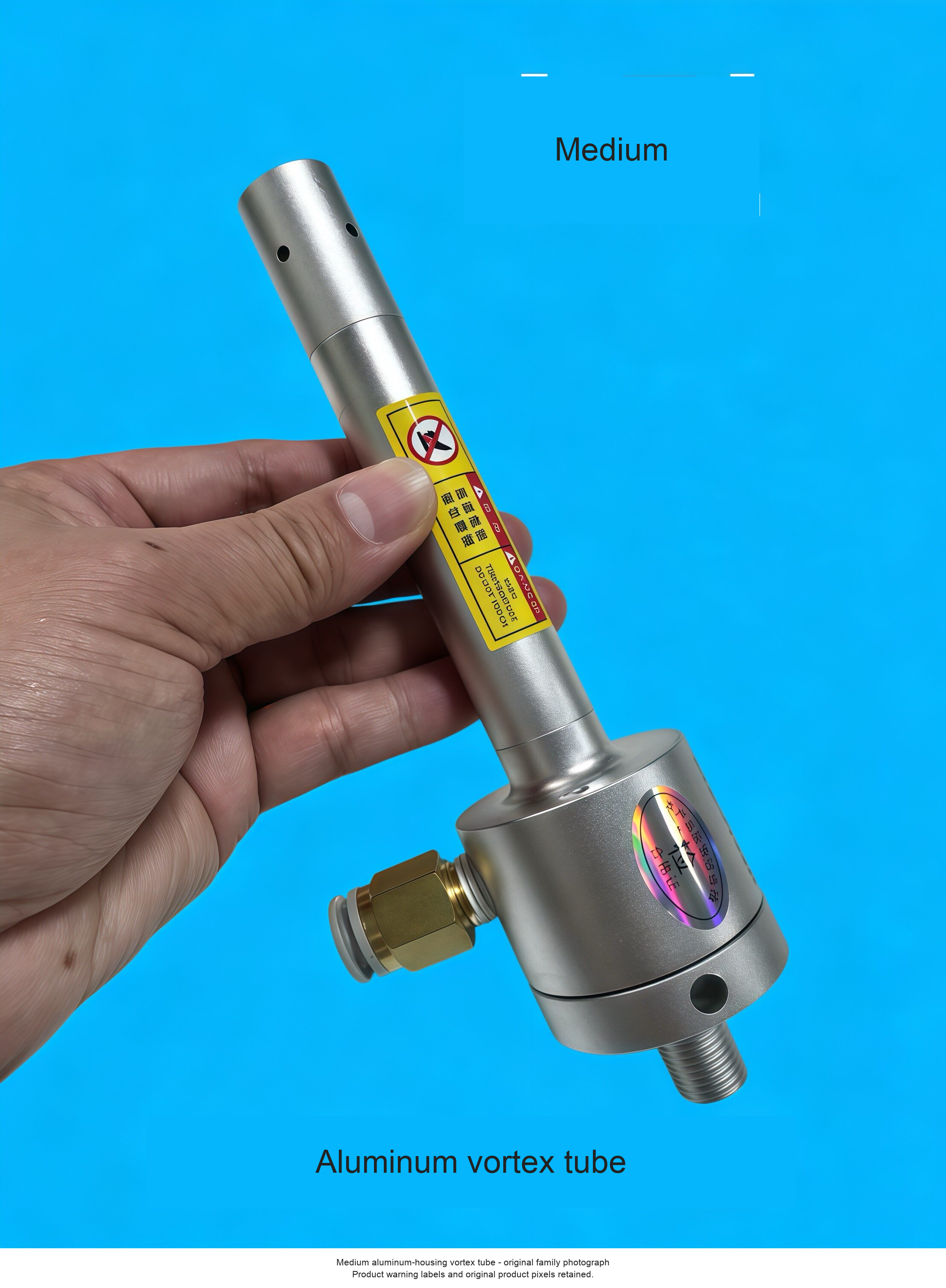
Vortex tubes separate a compressed-air supply into hot and cold outlet streams. Use the cold stream for localized industrial cooling where the process and installation permit. This page offers stainless-steel and aluminum-housing tube families, magnetic-base configurations and separately priced hoses and base accessories. Choose one option carefully: the accessory-only selections do not include a vortex tube.
Choose the Correct Configuration
| Selection | Original USD | Sale USD |
|---|---|---|
| RTK-VT02 - Stainless / Small | 580 | 464.00 |
| RTK-VT04 - Stainless / Small | 580 | 464.00 |
| RTK-VT08 - Stainless / Small | 580 | 464.00 |
| RTK-VT10 - Stainless / Small | 580 | 464.00 |
| RTK-VT15 - Stainless / Medium | 780 | 624.00 |
| RTK-VT25 - Stainless / Medium | 780 | 624.00 |
| RTK-VT30 - Stainless / Medium | 780 | 624.00 |
| RTK-VT40 - Stainless / Medium | 780 | 624.00 |
| RTK-VT50 - Stainless / Large | 2650 | 2120.00 |
| RTK-VT75 - Stainless / Large | 2650 | 2120.00 |
| RTK-VT100 - Stainless / Large | 2650 | 2120.00 |
| RTK-VT15X - Stainless / Medium / Magnetic base | 930 | 744.00 |
| RTK-VT25X - Stainless / Medium / Magnetic base | 930 | 744.00 |
| RTK-VT30X - Stainless / Medium / Magnetic base | 930 | 744.00 |
| RTK-VT40X - Stainless / Medium / Magnetic base | 930 | 744.00 |
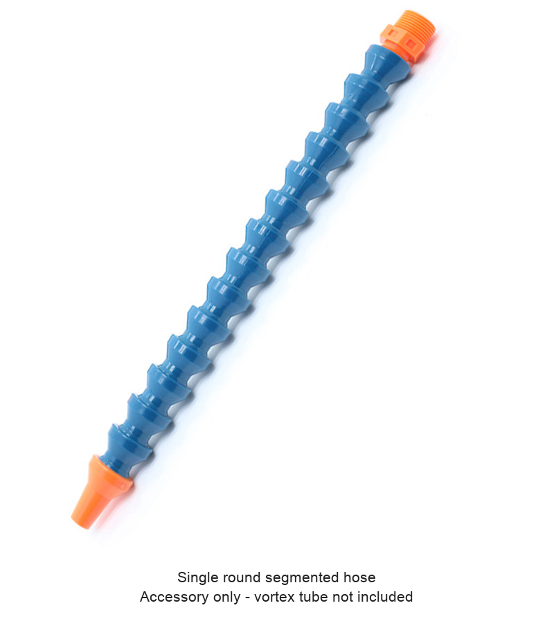
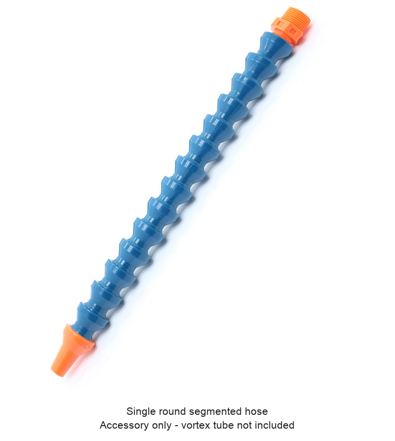
| Single round hose - accessory only | 50 | 40.00 |
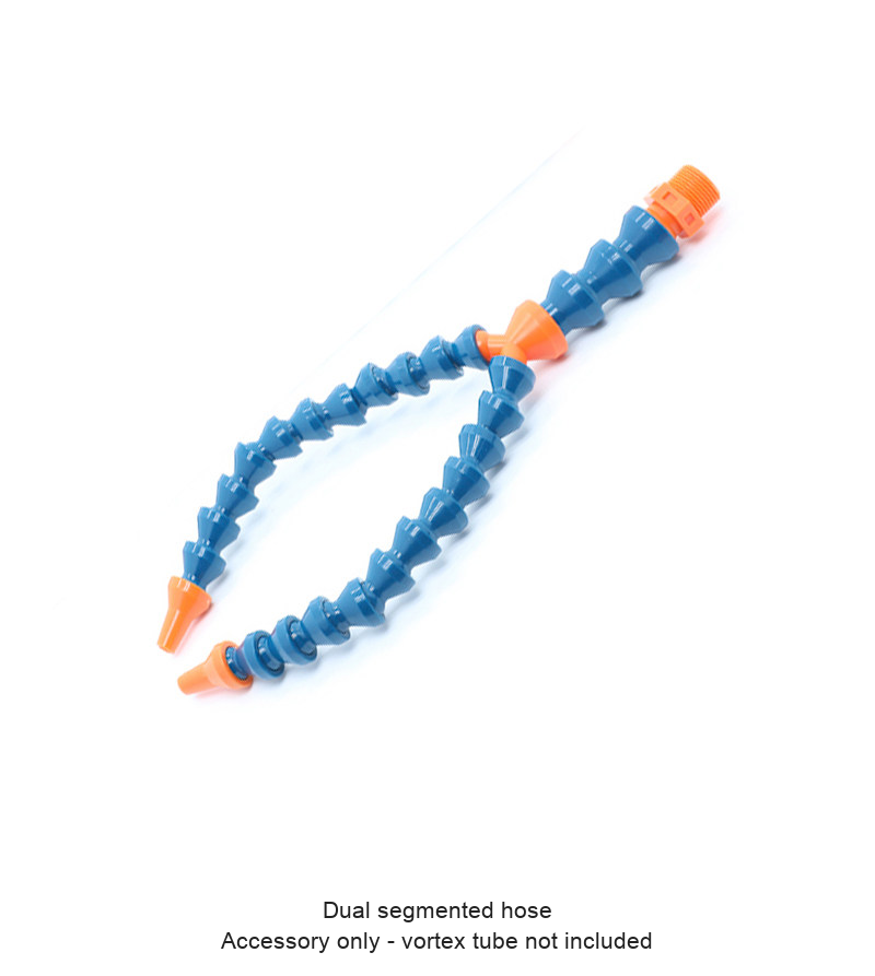
| Dual hose - accessory only | 60 | 48.00 |
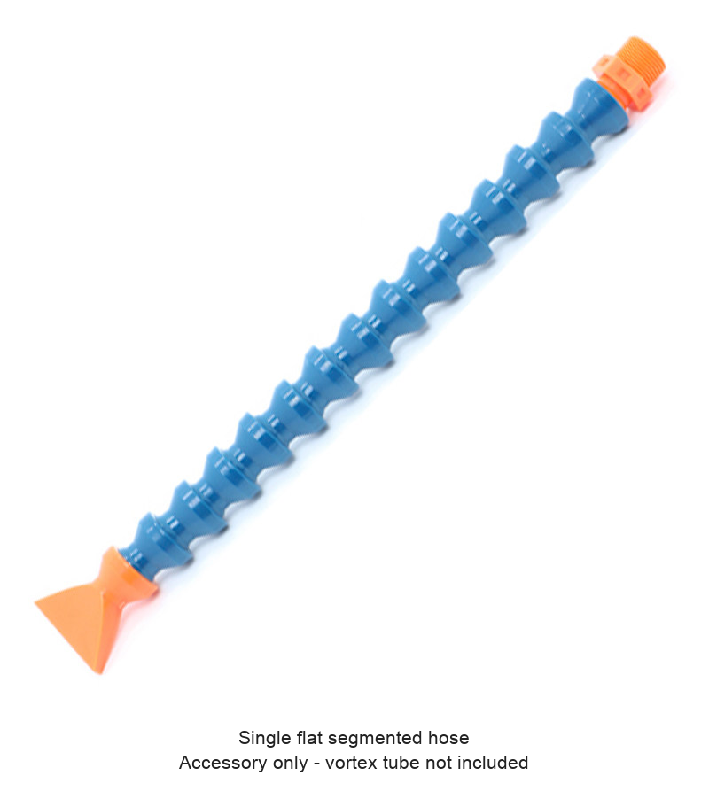
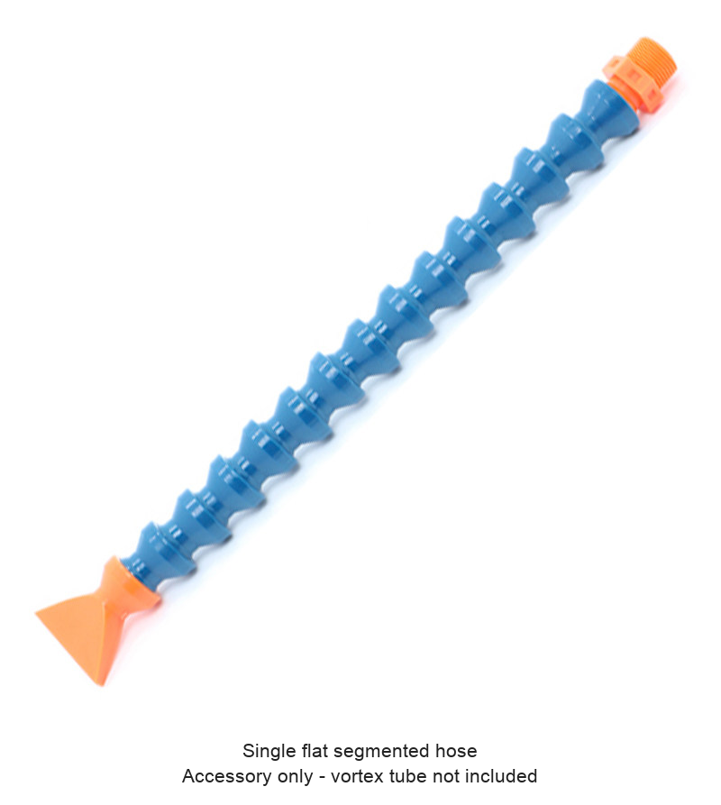
| Single flat hose - accessory only | 50 | 40.00 |
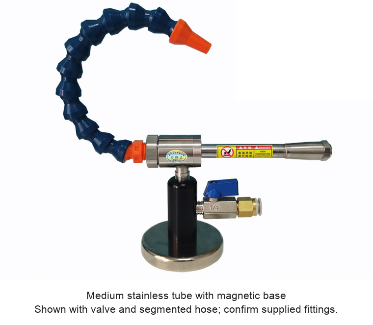
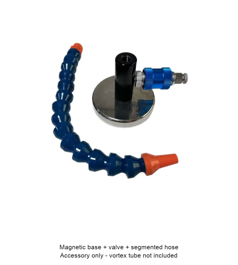
| Magnetic base + valve + hose - no vortex tube | 180 | 144.00 |
| RTK-VT02H - Aluminum / Small | 360 | 288.00 |
| RTK-VT04H - Aluminum / Small | 360 | 288.00 |
| RTK-VT08H - Aluminum / Small | 360 | 288.00 |
| RTK-VT10H - Aluminum / Small | 360 | 288.00 |
| RTK-VT15H - Aluminum / Medium | 580 | 464.00 |
| RTK-VT25H - Aluminum / Medium | 580 | 464.00 |
| RTK-VT30H - Aluminum / Medium | 580 | 464.00 |
| RTK-VT40H - Aluminum / Medium | 580 | 464.00 |
| RTK-VT02X - Stainless / Small / Magnetic base | 680 | 544.00 |
| RTK-VT04X - Stainless / Small / Magnetic base | 680 | 544.00 |
| RTK-VT08X - Stainless / Small / Magnetic base | 680 | 544.00 |
| RTK-VT10X - Stainless / Small / Magnetic base | 680 | 544.00 |
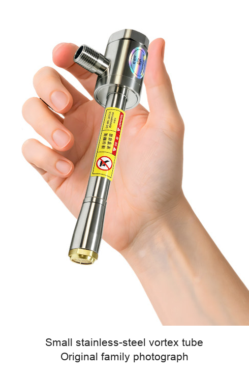
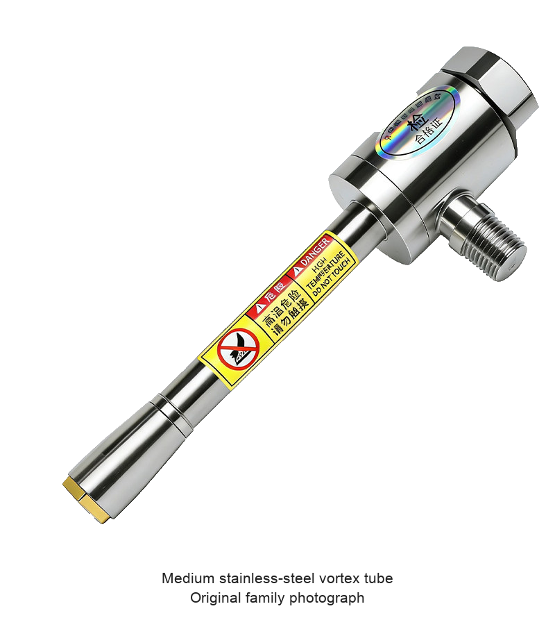
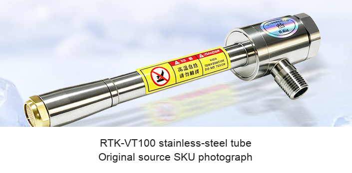
In this RTK-VT family, H identifies the aluminum-housing options, and X identifies the stainless-steel magnetic-base configurations. Small, medium and large descriptions are source family categories, not dimensions inferred from the model number. Shared photographs illustrate each family; confirm the exact supplied model and connections.
How It Works and Where It Is Used
Compressed air enters the vortex body and separates into a cold stream and a hot exhaust. A temperature/flow adjustment changes the balance. The tube itself is described as needing no electrical connection or refrigerant charge; an external compressor and appropriate air treatment are still required. Keep the hot exhaust clear and avoid contact with hot surfaces.
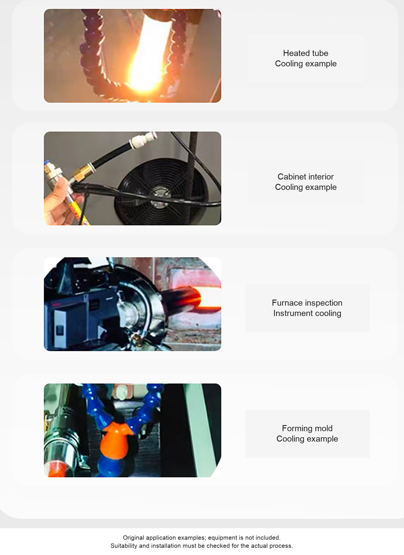
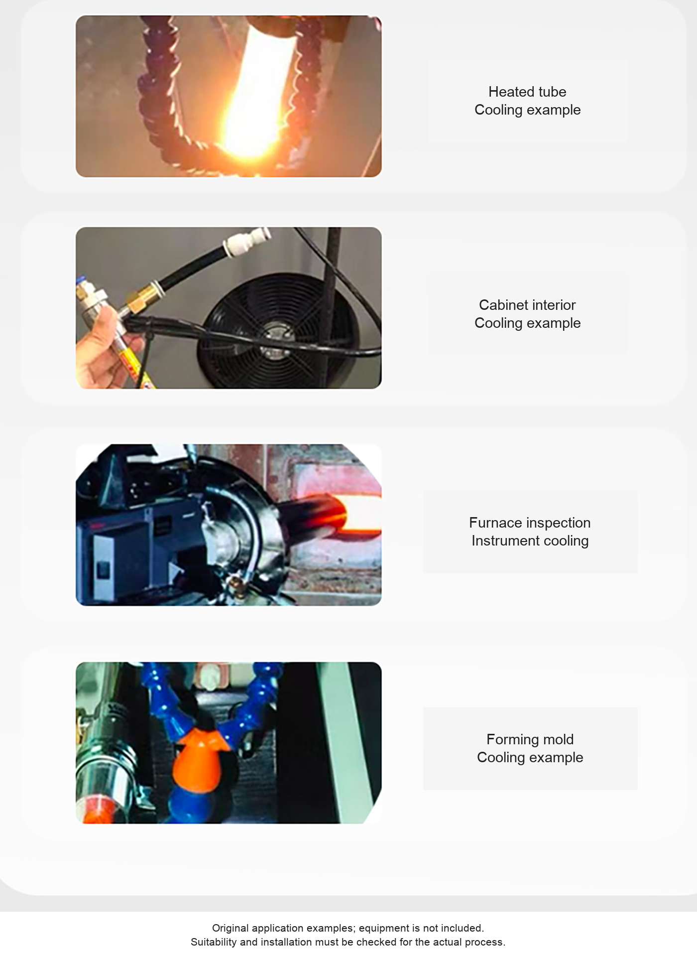
The supplied application photographs show heated-tube cooling, cabinet-interior cooling, an inspection-instrument installation and mold cooling. Other source examples include plastics or metal processing, wood processing, welding, bonding and local cooling around tools or equipment. These are application examples. Verify the actual temperature, air quality, exhaust routing and compatibility for the intended process before use.
Tube and Accessory Contents
Plain tube selections are the selected vortex tube. X selections are pictured with a magnetic base, flow valve and segmented outlet hose; confirm the exact supplied fittings. H selections use the pictured aluminum housing. Single-round, dual and single-flat hose options are individual hose accessories, not complete cooling systems. The magnetic-base accessory option consists of the base, valve and segmented hose, without a vortex tube. Compressors, filters/regulators, machinery and workpieces shown are not specified as included.
Supplier Performance References
| Base model | SCFM | SLPM | Btu/hr | kcal/hr |
|---|---|---|---|---|
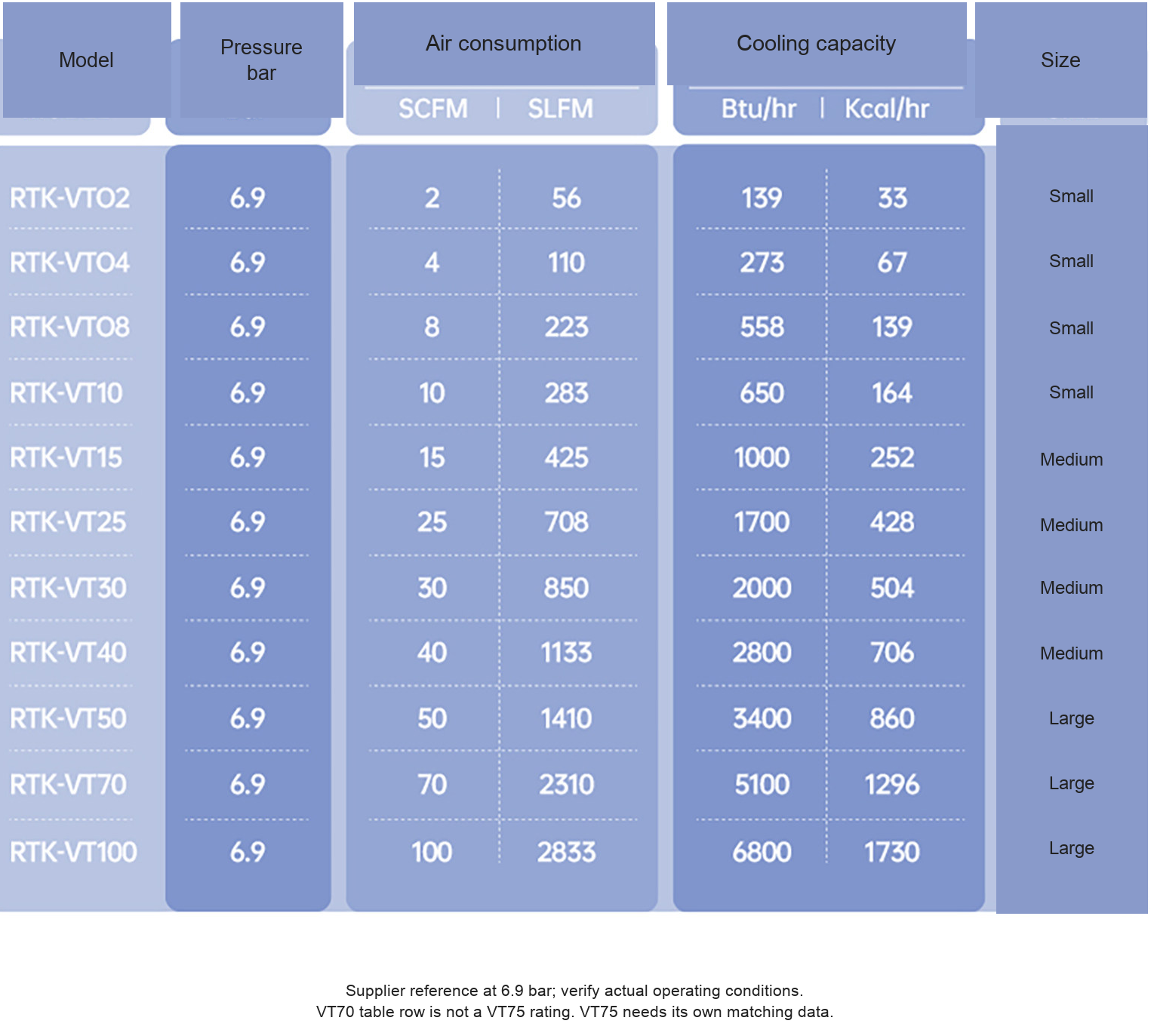
| VT02 | 2 | 56 | 139 | 33 |
| VT04 | 4 | 110 | 273 | 67 |
| VT08 | 8 | 223 | 558 | 139 |
| VT10 | 10 | 283 | 650 | 164 |
| VT15 | 15 | 425 | 1000 | 252 |
| VT25 | 25 | 708 | 1700 | 428 |
| VT30 | 30 | 850 | 2000 | 504 |
| VT40 | 40 | 1133 | 2800 | 706 |
| VT50 | 50 | 1410 | 3400 | 860 |
| VT70 (reference only) | 70 | 2310 | 5100 | 1296 |
| VT100 | 100 | 2833 | 6800 | 1730 |
The source table is stated at 6.9 bar (0.69 MPa, approximately 100 psi). Values above reproduce its entries without assigning every base-model row as a certified rating for every H/X configuration. The priced large option is VT75, but the table instead prints VT70. VT70 is reference-only and is not selectable here; no matching separate VT75 performance row is established. The VT70 row prints 70 SCFM and 2310 SLPM together; verify the required airflow before compressor sizing rather than assuming these entries are mutually converted values.
The source gives conflicting temperature and temperature-drop claims. A fixed outlet temperature or drop is not promised. Actual performance depends on inlet conditions, pressure and delivered flow, adjustment, outlet fittings and process conditions.
Original Dimensions and Connection References
| Reference drawing | Dimensions / calculated inch reference | Connection markings and limits |
|---|---|---|
| Small | 135.50 mm overall (5.335 in); 48 mm span (1.890 in); body diameter 26 mm (1.024 in), shaft 10 mm (0.394 in), hot end 17 mm (0.669 in) | PT1/8 inlet; PT1/4 cold outlet as printed. |
| Medium | 114.50 mm partial span (4.508 in), not confirmed overall; head span 48 mm (1.890 in), body diameter 30 mm (1.181 in), shaft 13 mm (0.512 in) | PT1/4 inlet; PT3/8 cold outlet as printed. |
| Large | 326 mm overall (12.835 in); 117 mm (4.606 in) and 30 mm (1.181 in) partials; diameter references 55/54/24/26.5 mm | PT1/2 inlet; source also prints NPT/NTP3/4 markings. Verify actual thread. |
These are original family reference drawings, not confirmed finished drawings for every H, X or accessory option. Inch values are calculated from 25.4 mm per inch. The general attributes state 1/4-inch NPT while individual drawings show size-dependent PT and other markings. Do not assume interchangeability. Confirm thread form, size, male/female arrangement and the selected model drawing before installing. The source pressure phrase 5-12KG has no clear complete unit, so it is not treated as an established maximum pressure.
Materials, Supply and Installation
The selected rows distinguish stainless-steel and aluminum housings. A general stainless description does not establish the grade of every component, and H models are not described as all stainless. This listing is for compressed-air use. The supplied material does not establish suitability or approval for natural-gas service.
- Select the exact tube family or accessory, and confirm its supplied connections and contents.
- Confirm the allowable pressure, actual airflow requirement and air-treatment instructions for that unit. Provide suitable controlled, clean and dry compressed air.
- Secure the tube and route both outlets safely. A magnetic base requires a suitable ferromagnetic mounting surface and a secure hold.
- Position the outlet without interference with moving parts or guarding, and keep the hot exhaust clear.
- Start under controlled conditions and measure the actual process result. Adjust only as instructed for the supplied unit.
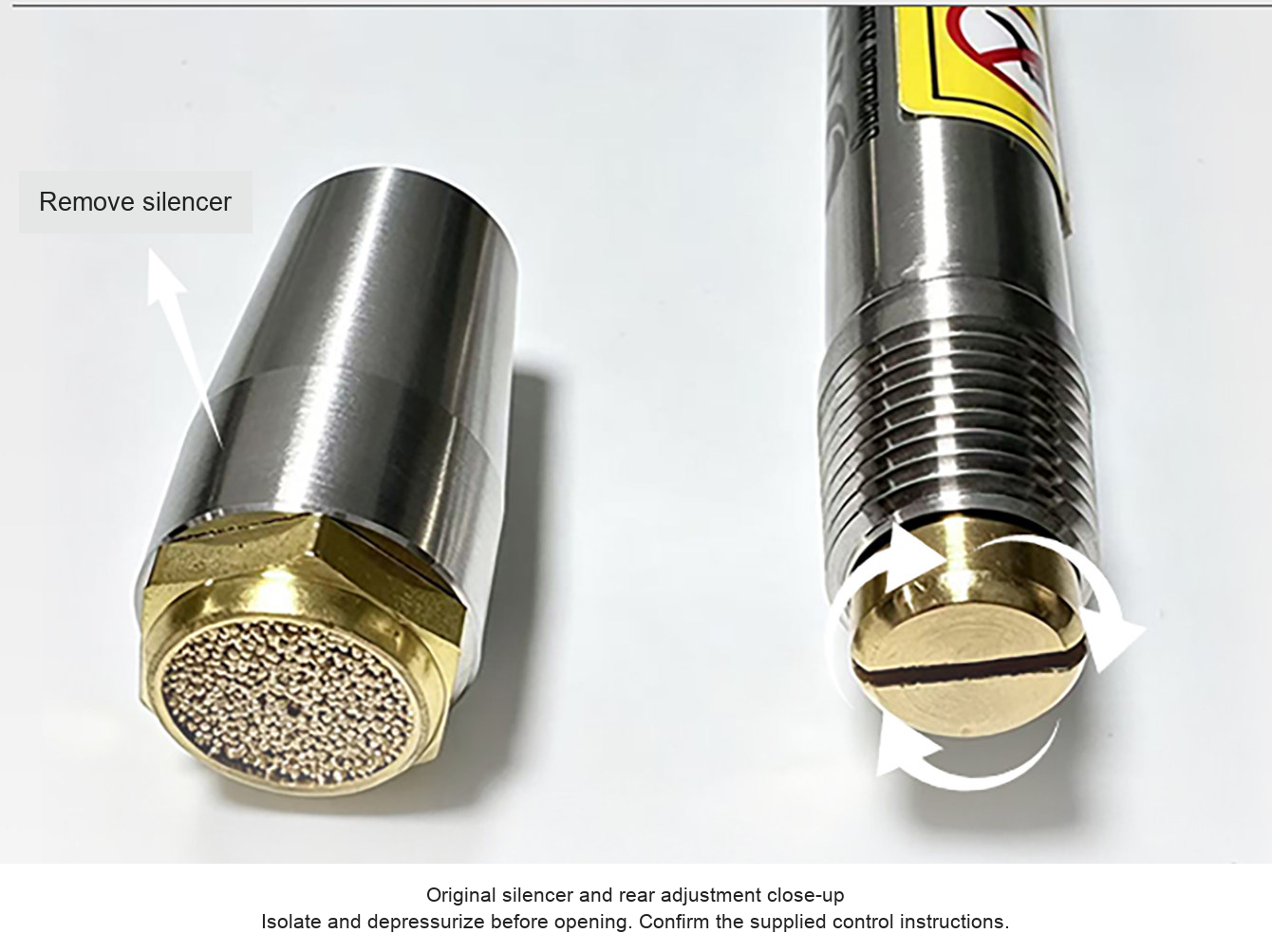
- Isolate and depressurize before opening the silencer, changing an internal setting, or replacing fittings and hoses. Do not force the adjustment screw fully shut.
Selection and Troubleshooting
If cooling is insufficient, first confirm pressure and delivered flow at the inlet, check restrictions and leaks, verify the adjustment and keep hot/cold outlets unobstructed. Contamination or moisture may affect operation; follow the supplied air-treatment and maintenance instructions. A different tube size may be necessary for the process. Do not infer a model rating from a photograph.
For help confirming a selection, send the model, application, available inlet pressure and airflow, fitting/thread requirement, mounting space and desired hose configuration to boltte@boltte.com.
Original Product, Drawing and Application Images
Original family photographs, accessory views, dimension lines, adjustment close-up, numerical table and four actual application photographs are retained below. Captions are translated; product geometry is preserved.