
D19L25 / D20L25 Aluminum Flexible Beam Couplings, Set Screw and Clamp
D19L25 and D20L25 Aluminum Flexible Beam Couplings
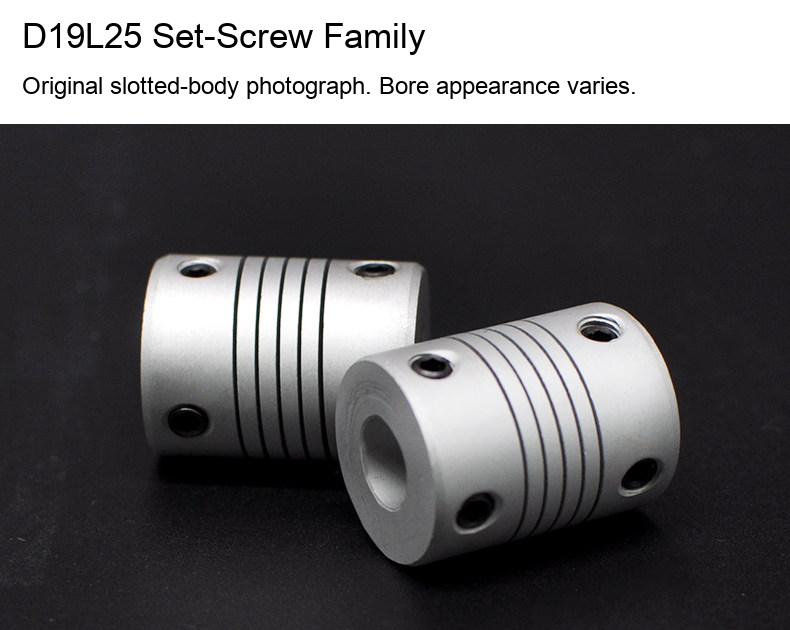
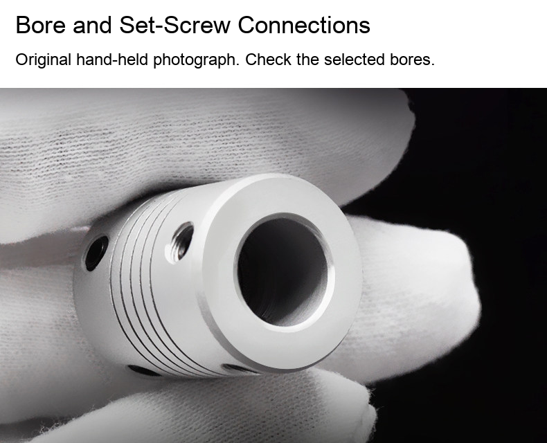
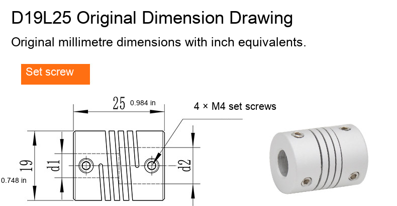
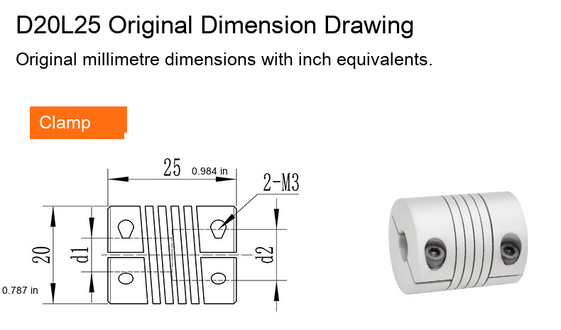
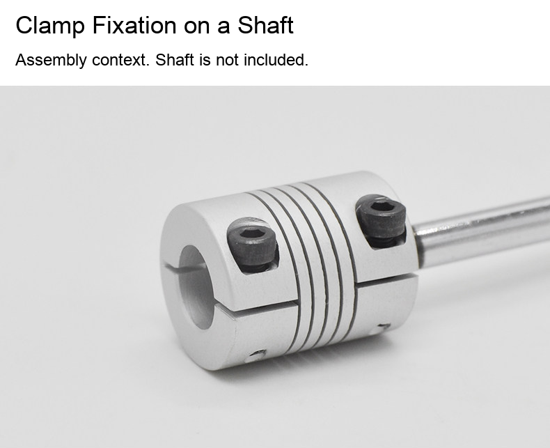
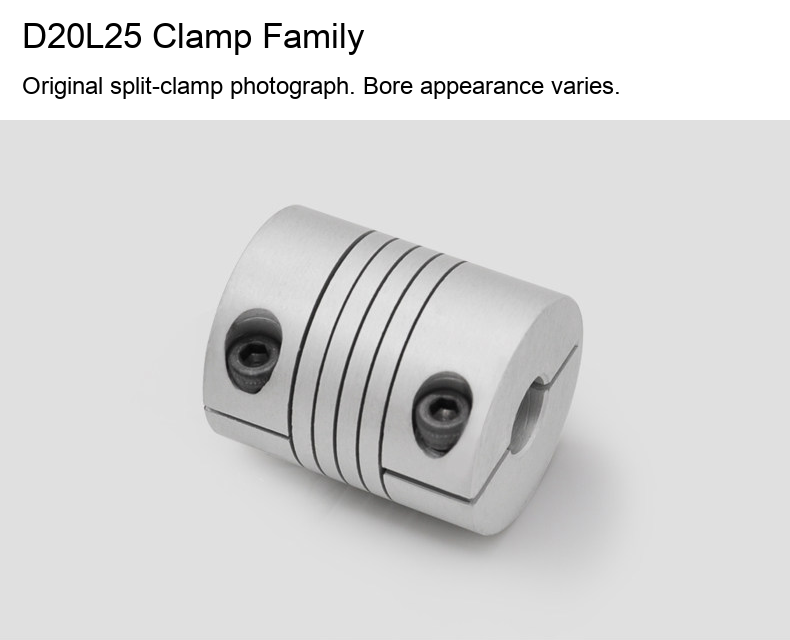
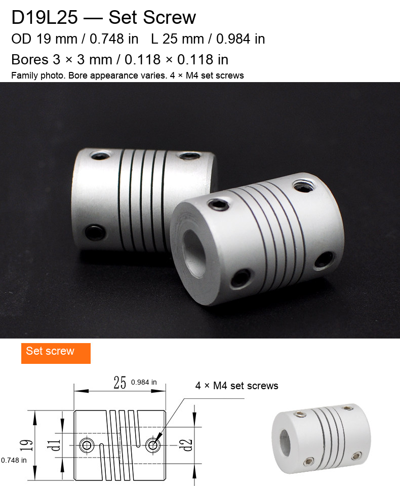
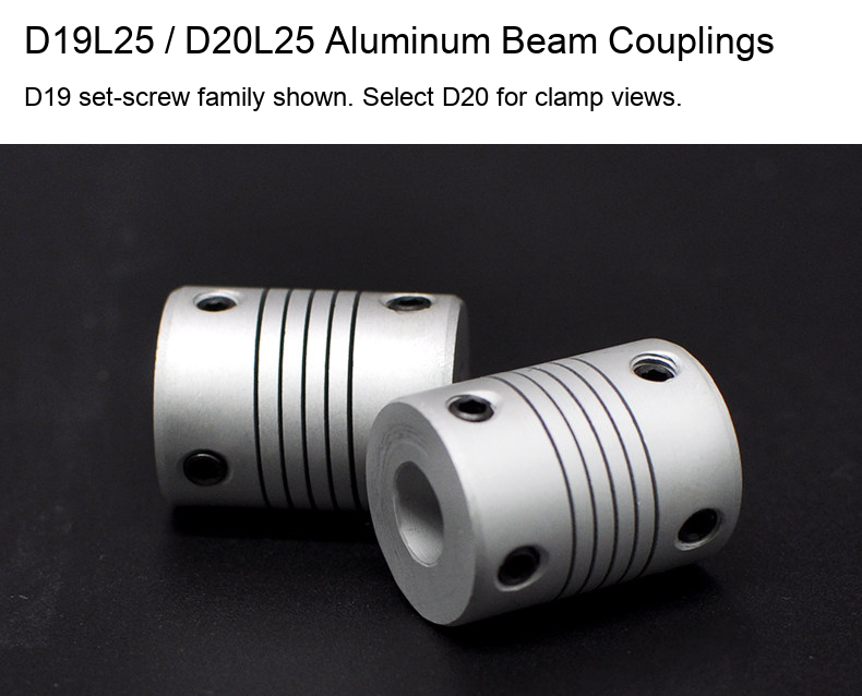
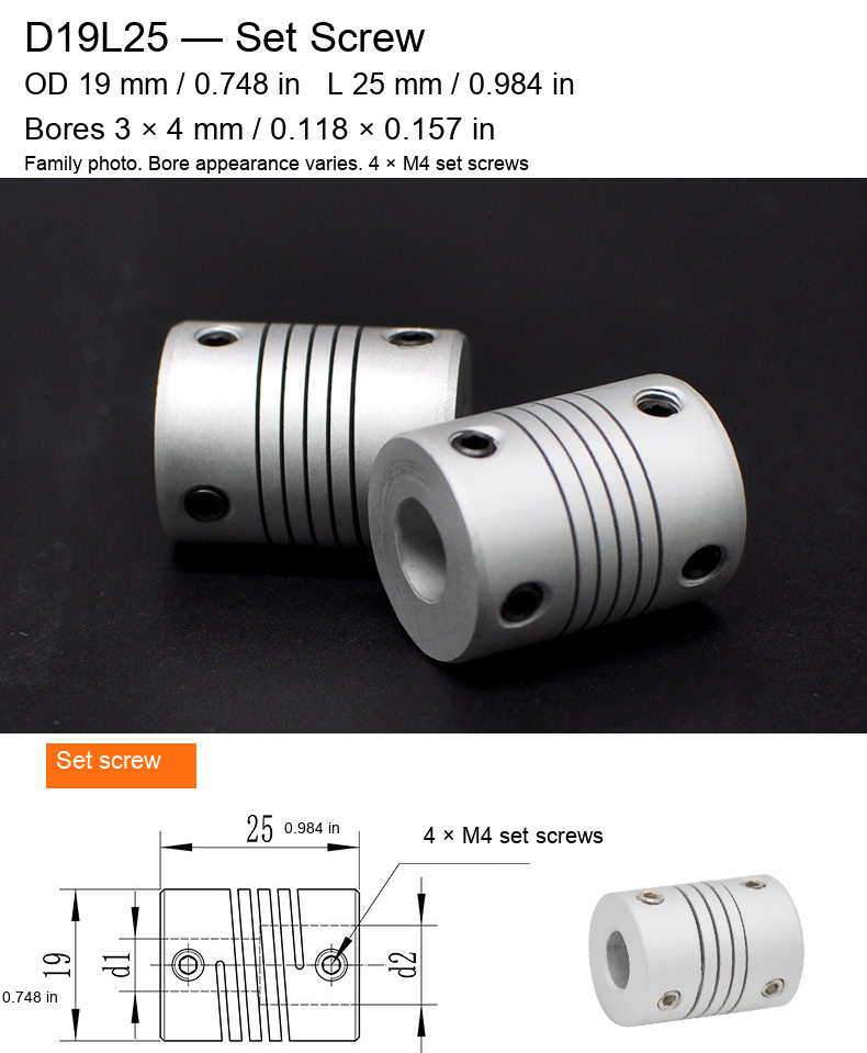
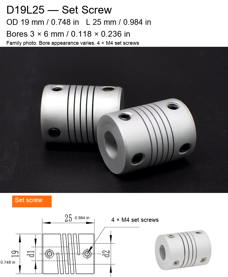
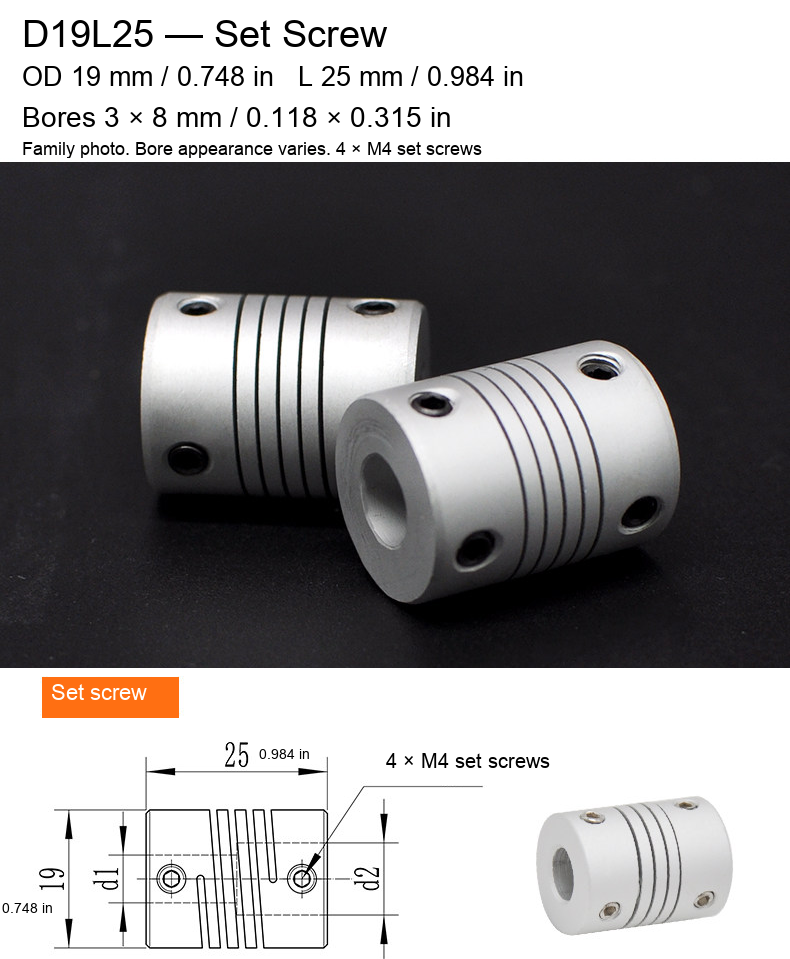
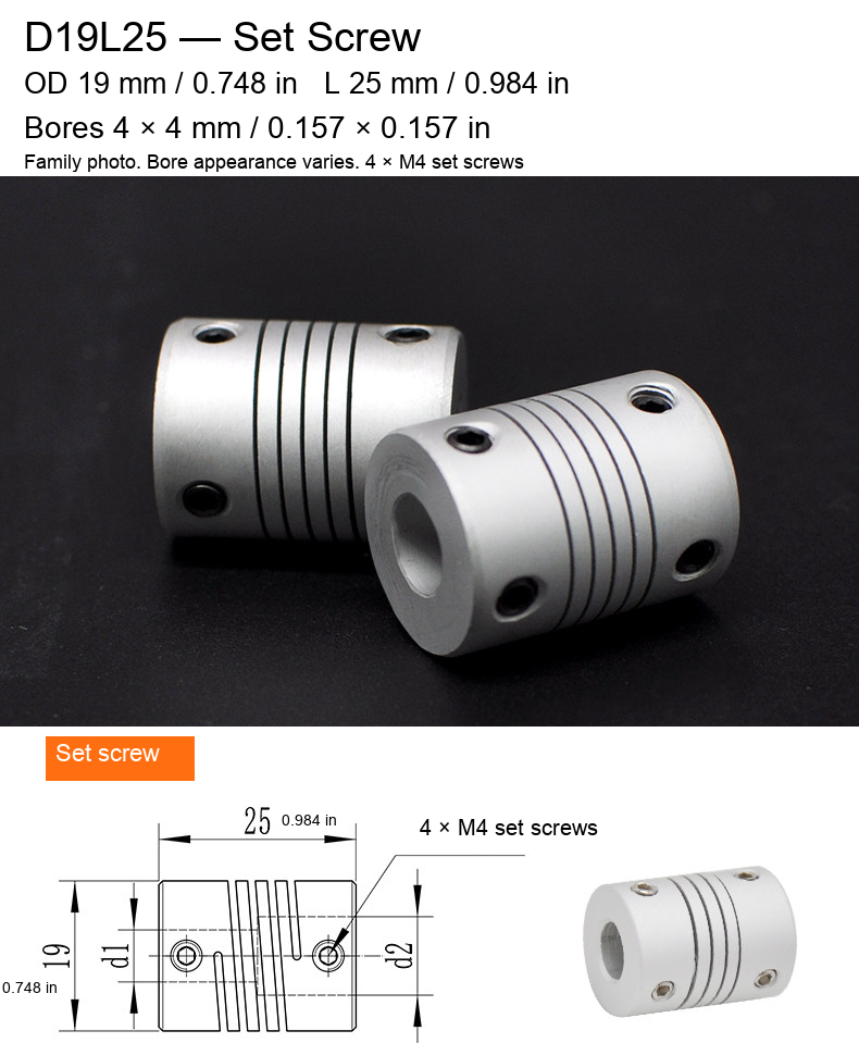
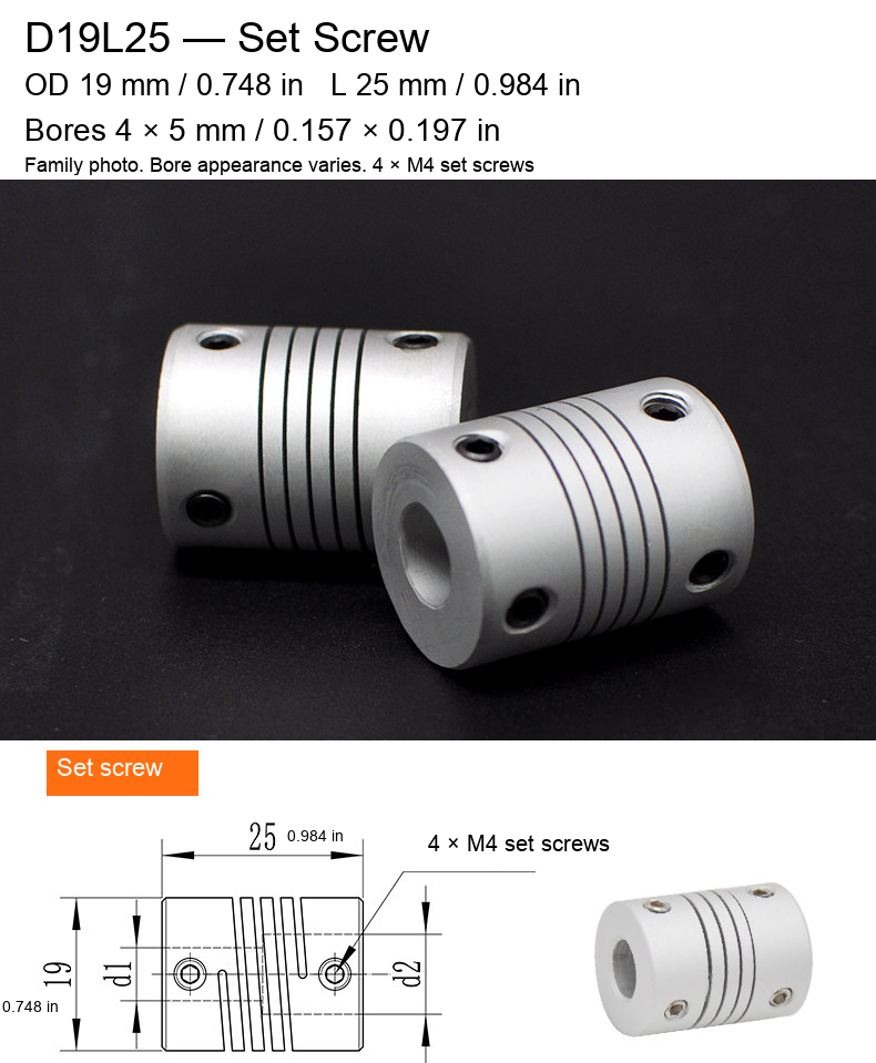
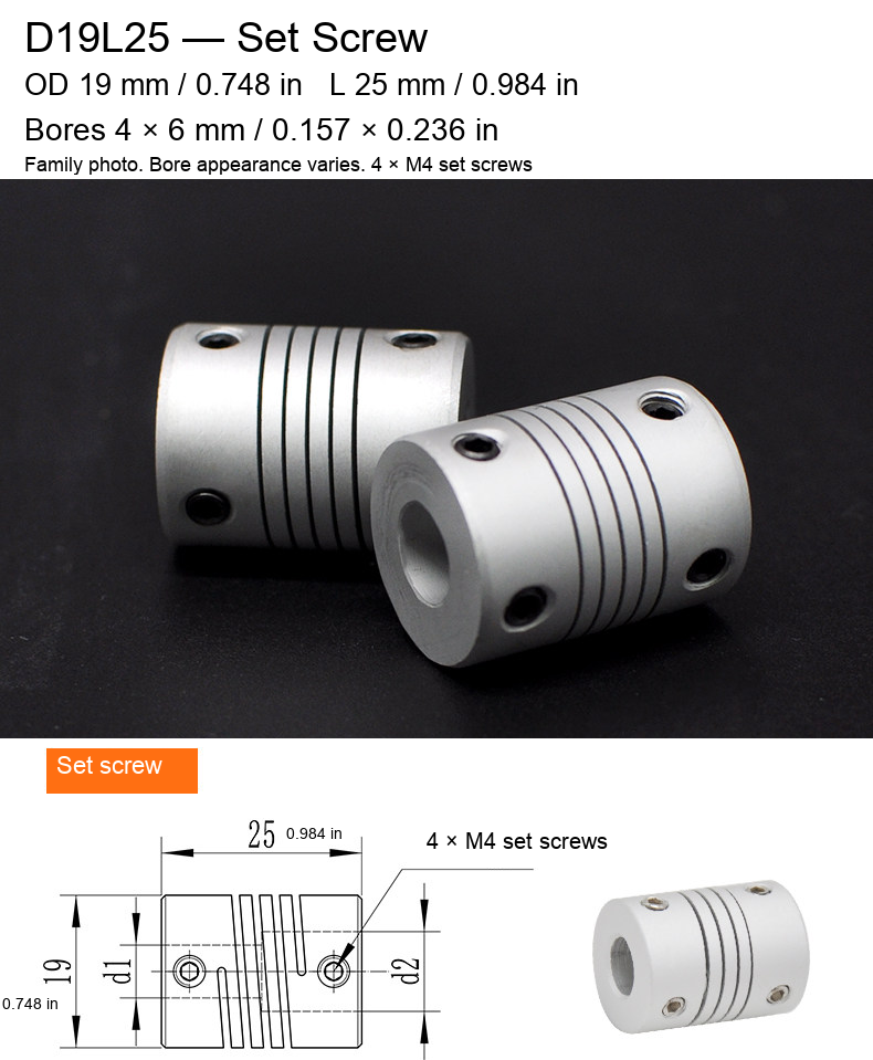
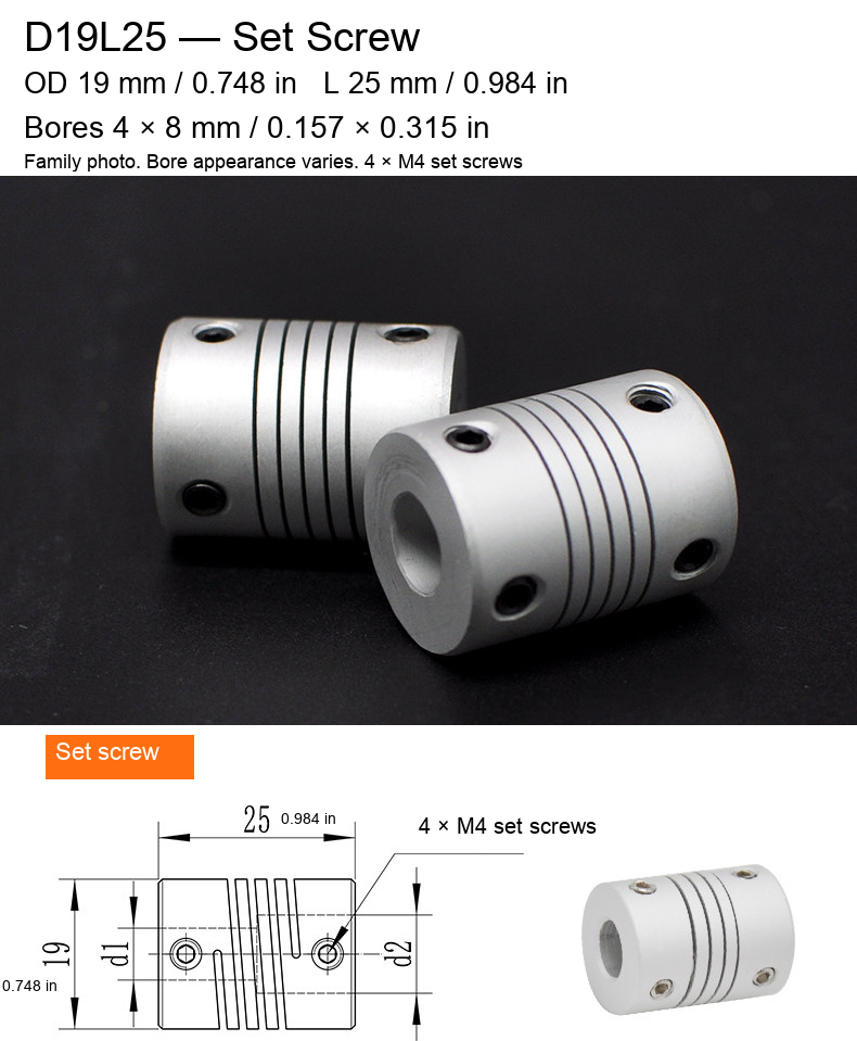
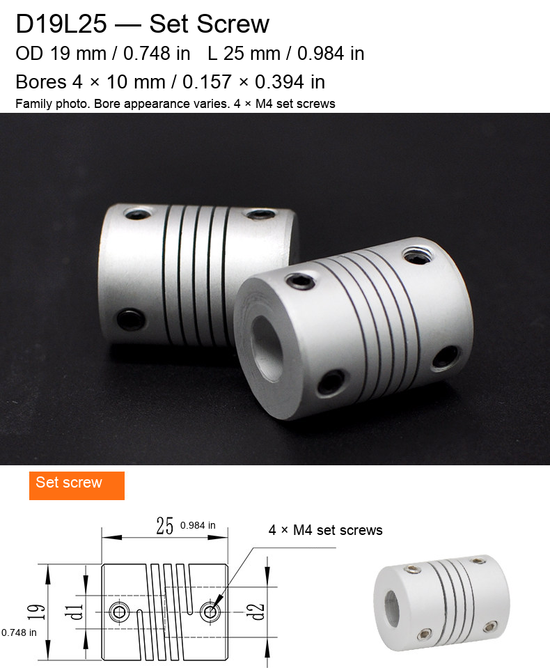
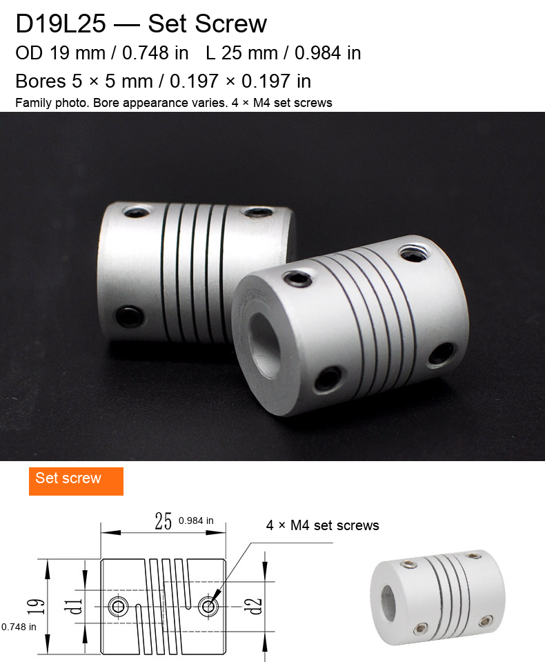
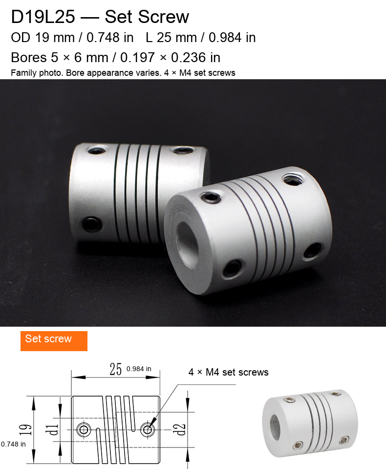
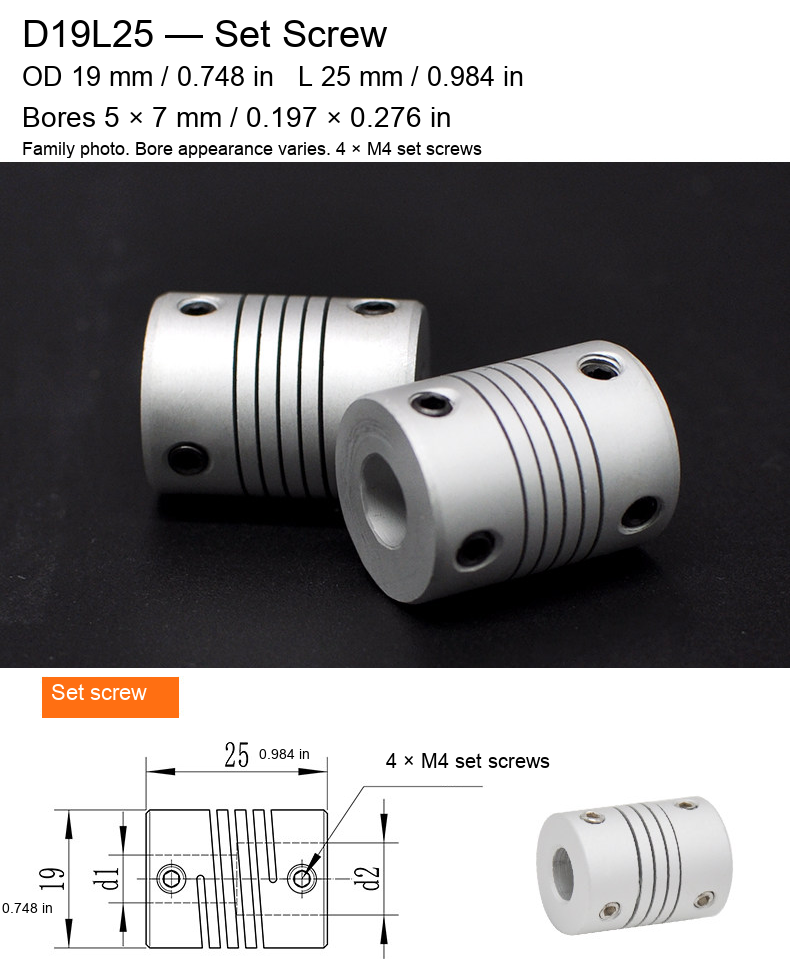
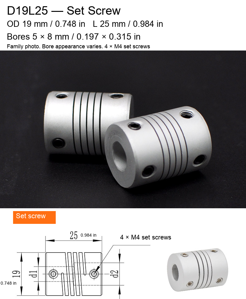
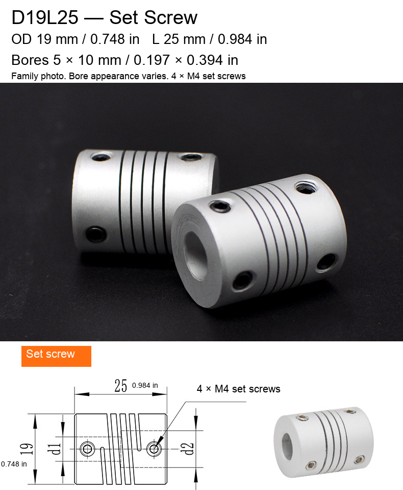
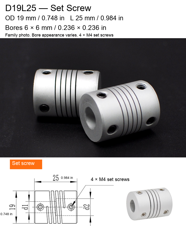
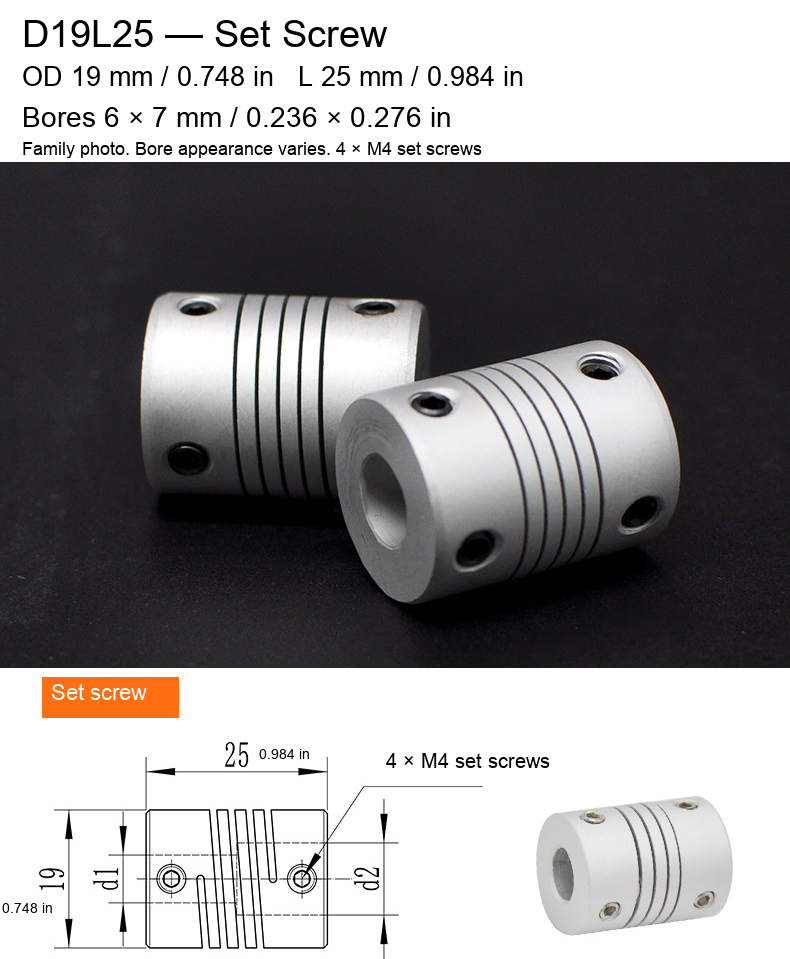
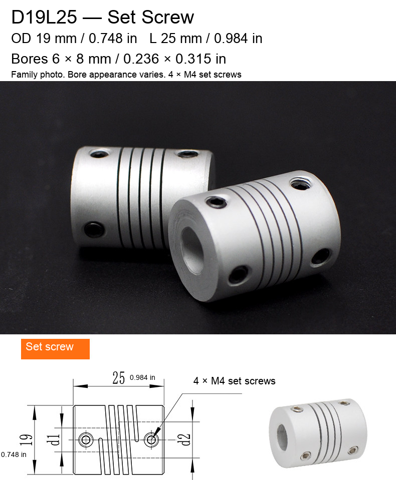
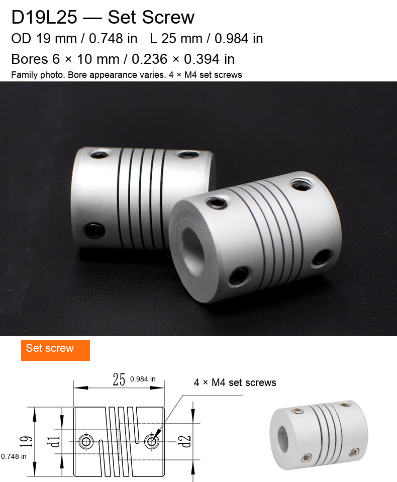
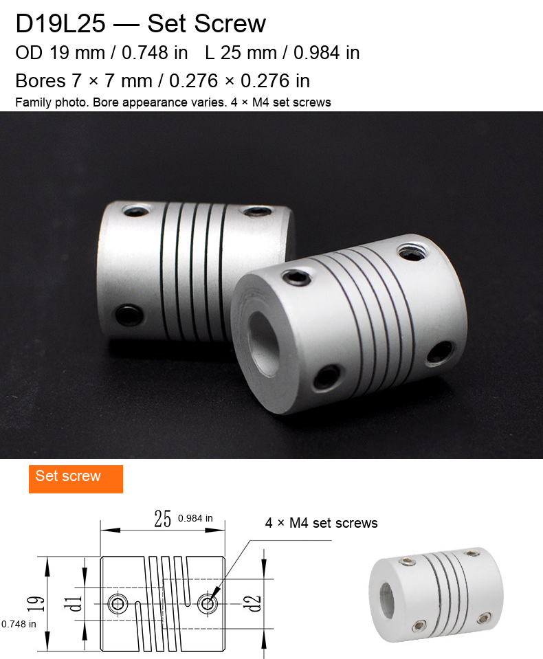
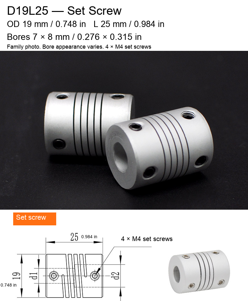
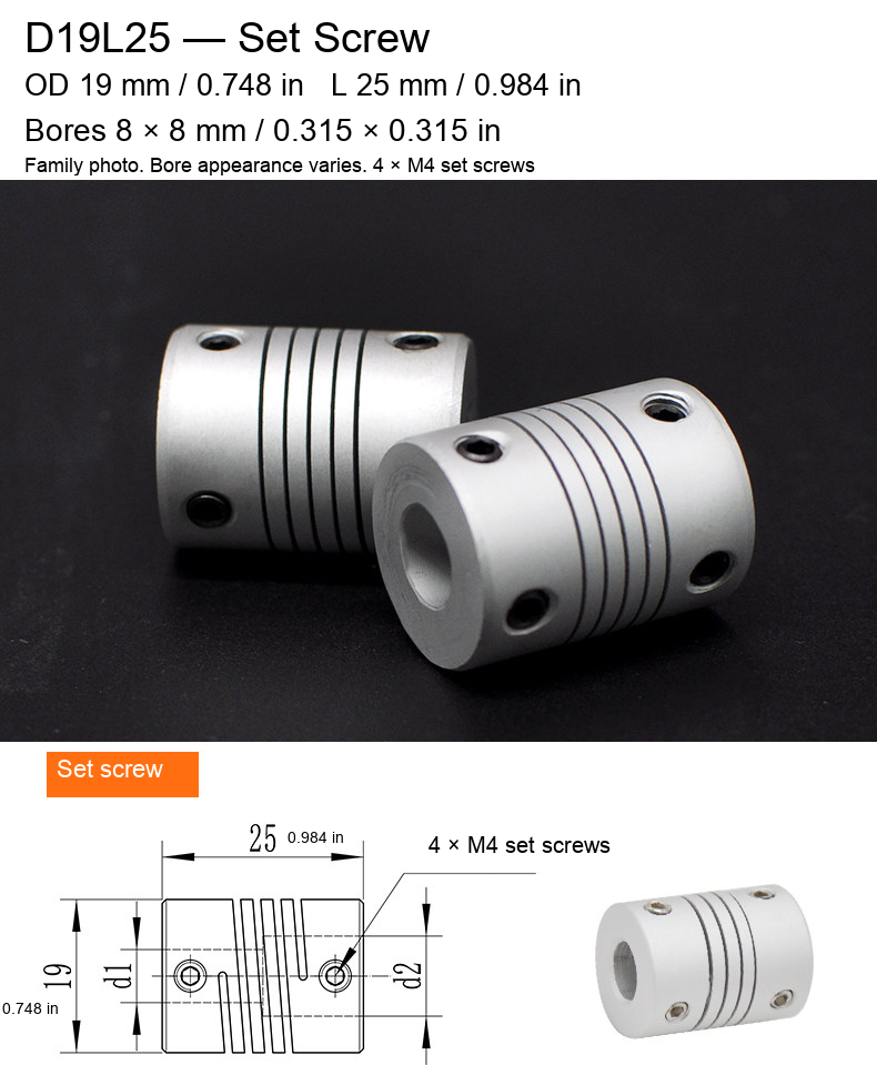
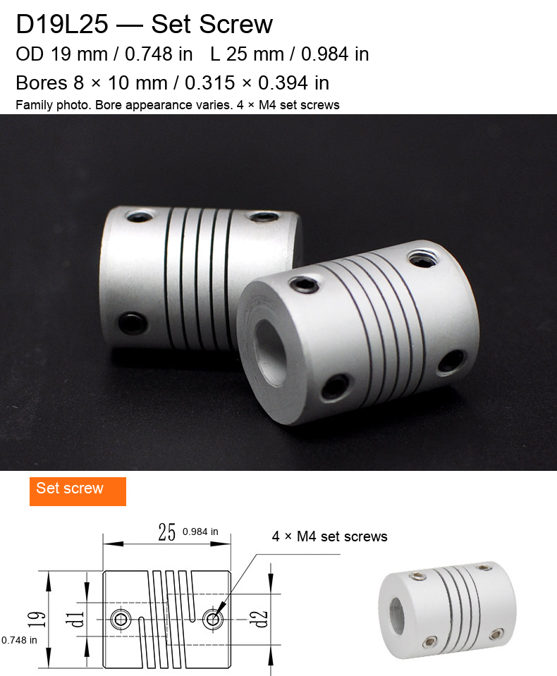
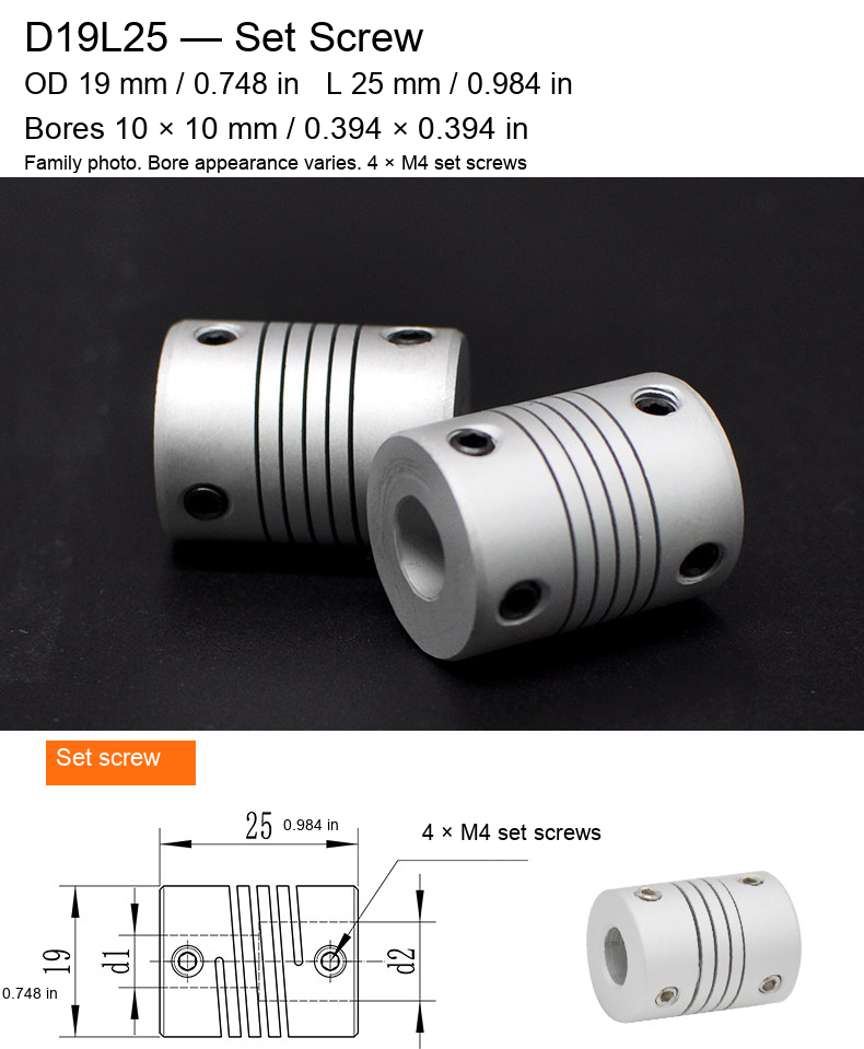
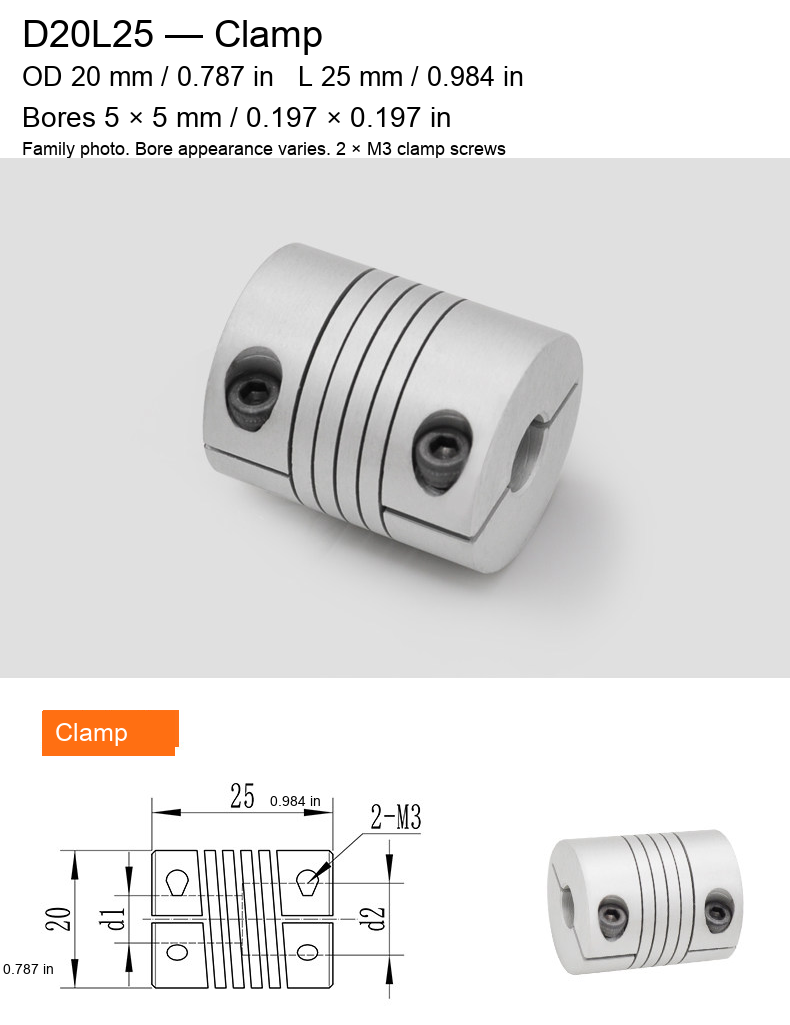
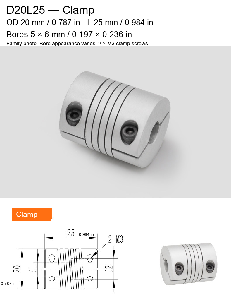
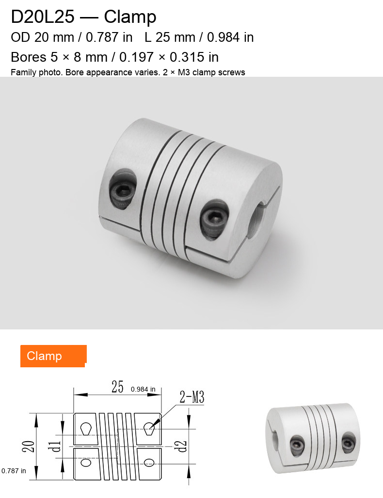
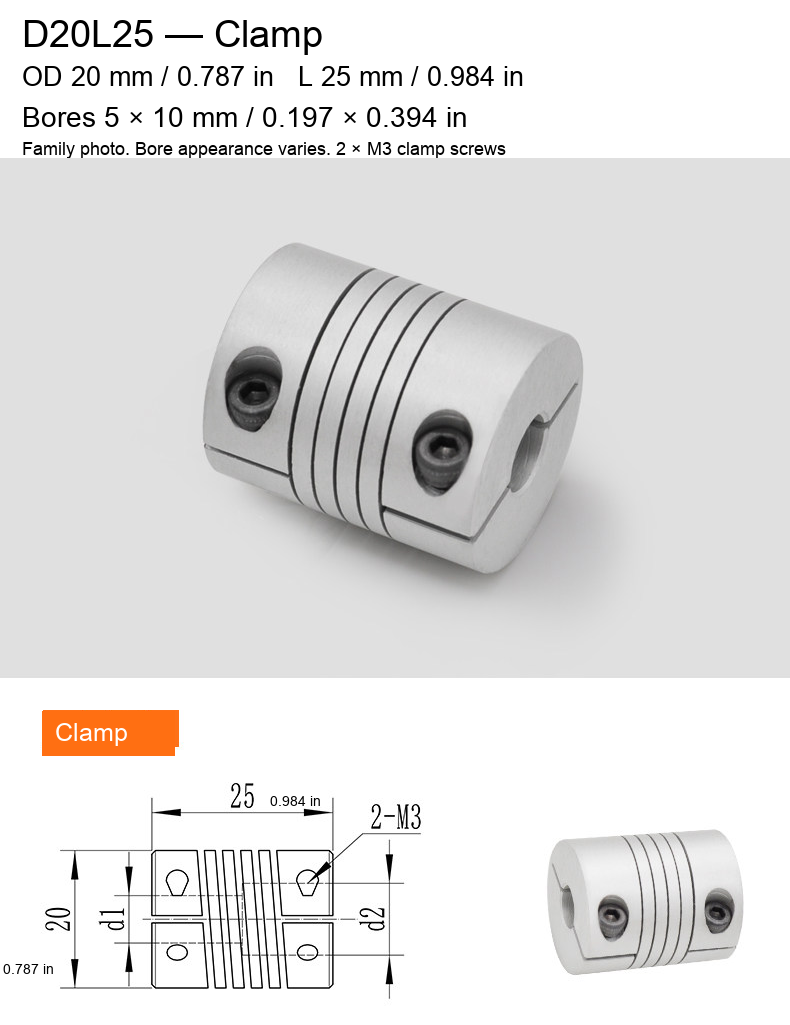
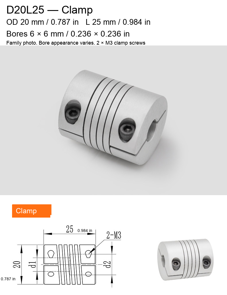
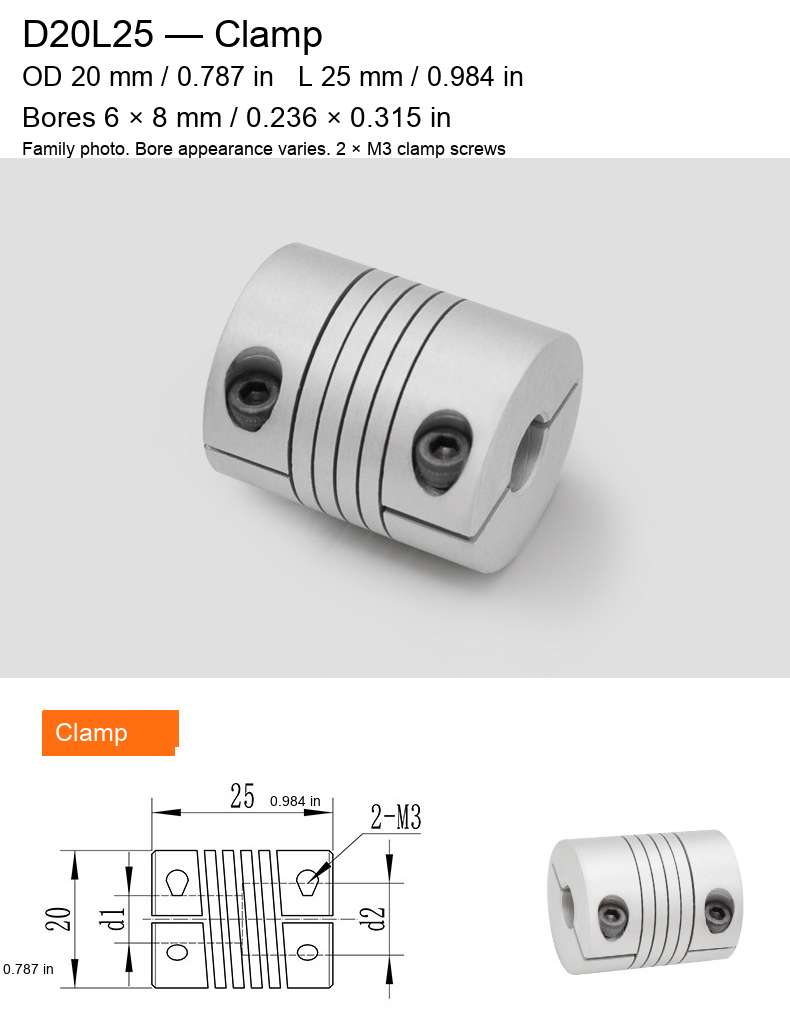
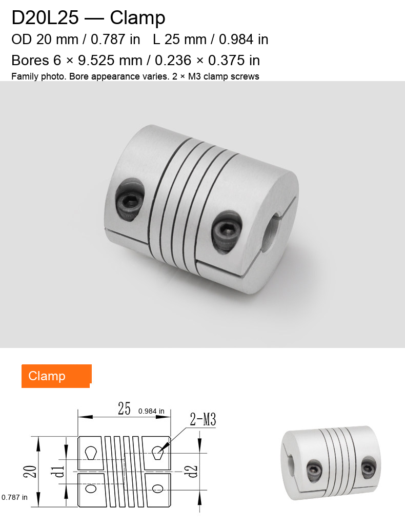
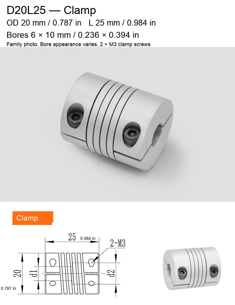
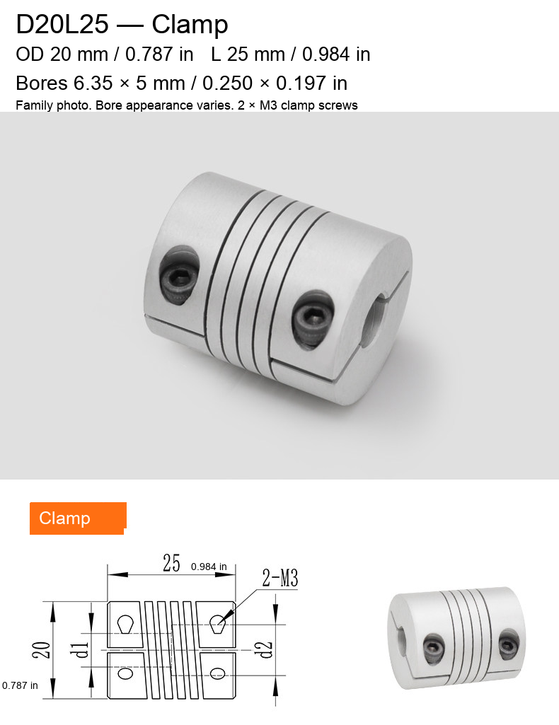
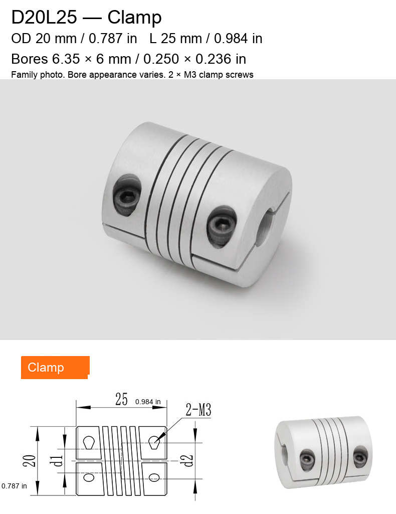
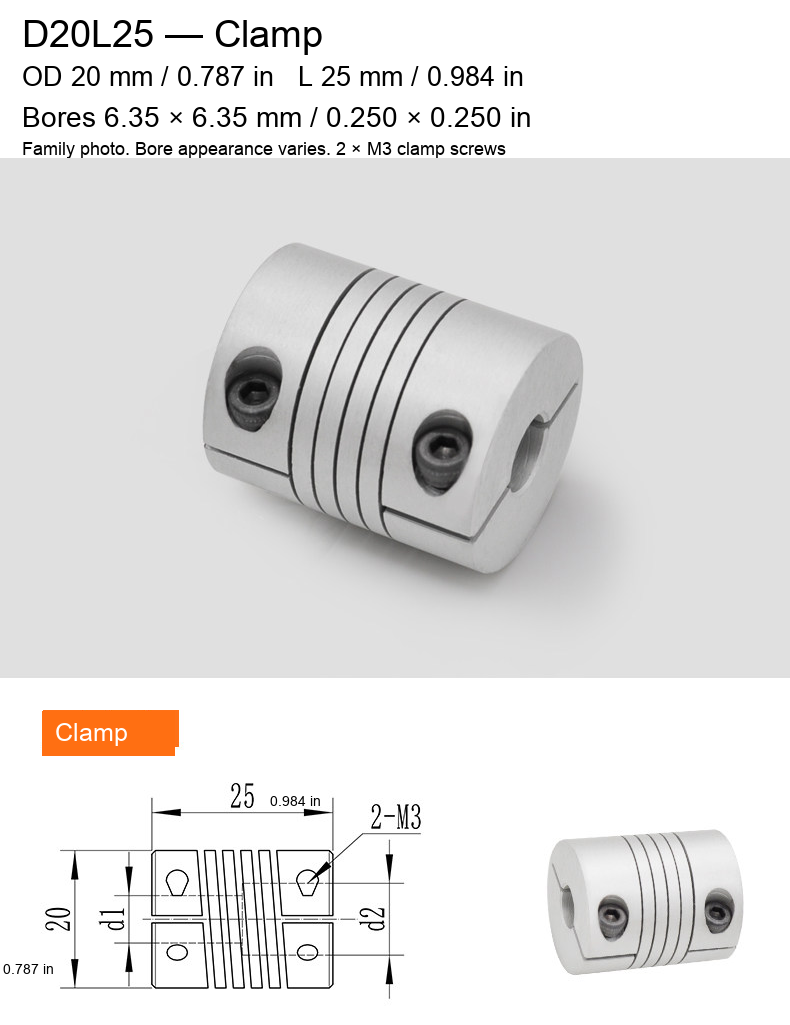
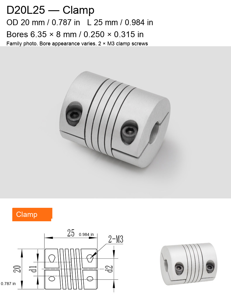
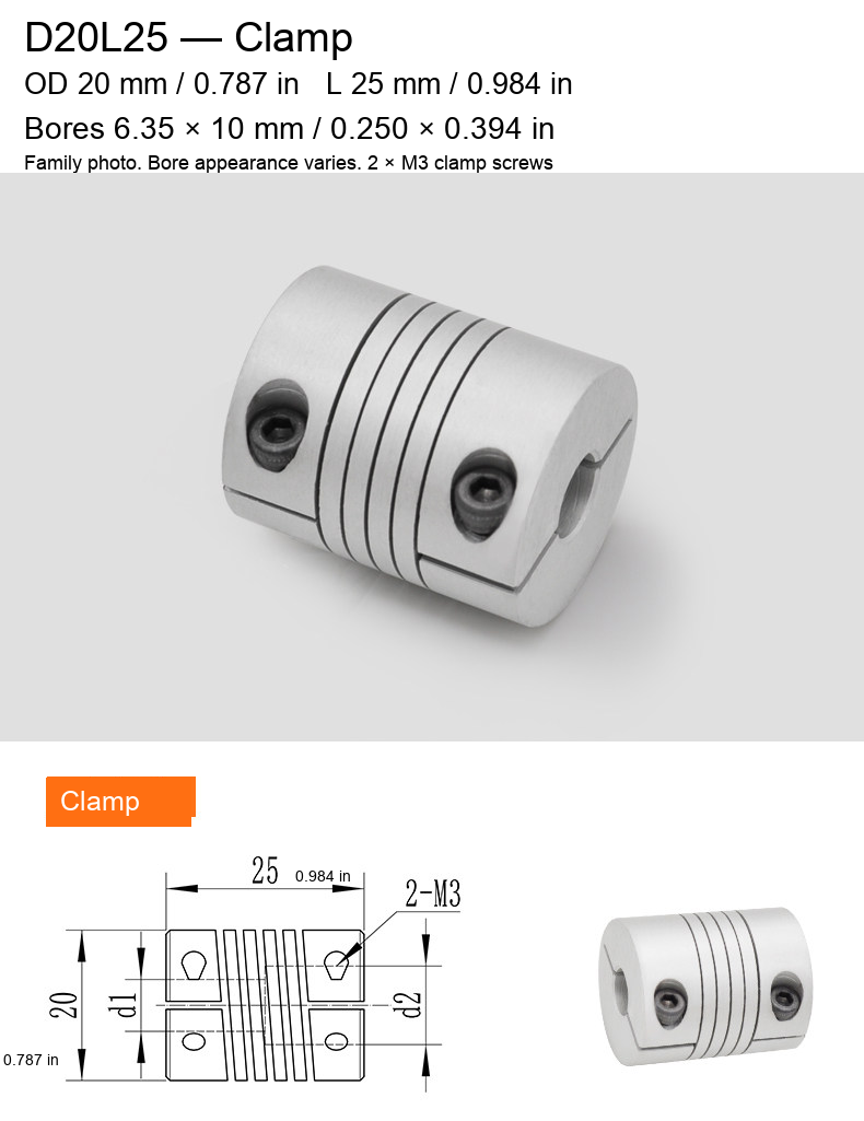
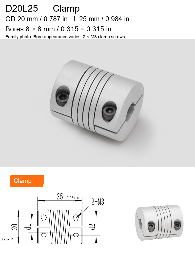
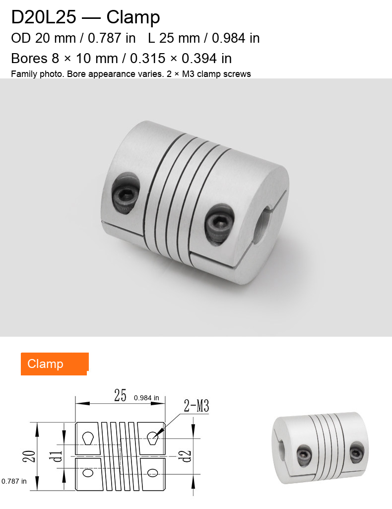
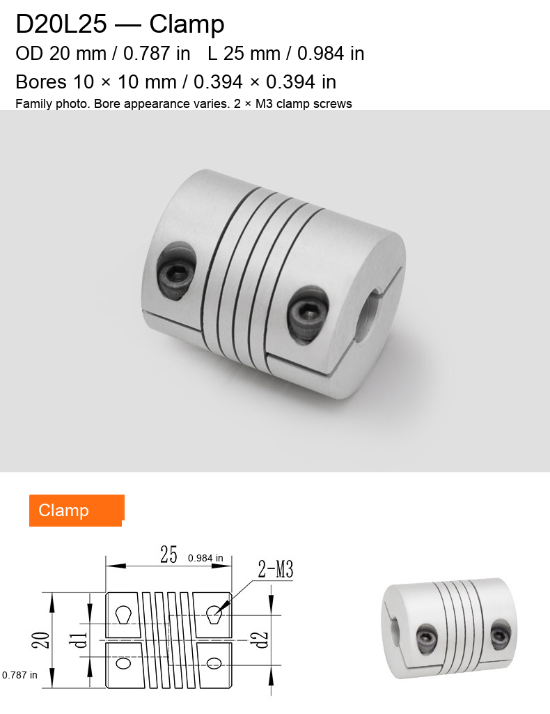
Two original-source fixation styles with exact selectable bore pairs. D19L25 is 19 mm (0.748 in) outside diameter and 25 mm (0.984 in) long, with four M4 set screws. D20L25 is 20 mm (0.787 in) outside diameter and 25 mm (0.984 in) long, with two M3 clamp screws. Metric screw designations are retained; they are not substituted with imperial threads.
Available Bore Pairs
Forty configurations are listed: 24 set-screw D19L25 options and 16 clamp D20L25 options. Millimetre values remain the source dimensions. Inch equivalents are rounded to three decimal places. A 6.35 mm bore is nominally 1/4 inch; 9.525 mm is nominally 3/8 inch.
| Model / fixation | Bore pair (mm) | Bore pair (in) |
|---|---|---|
| D19L25 / Set Screw | 3 × 3 | 0.118 × 0.118 |
| D19L25 / Set Screw | 3 × 4 | 0.118 × 0.157 |
| D19L25 / Set Screw | 3 × 5 | 0.118 × 0.197 |
| D19L25 / Set Screw | 3 × 6 | 0.118 × 0.236 |
| D19L25 / Set Screw | 3 × 8 | 0.118 × 0.315 |
| D19L25 / Set Screw | 4 × 4 | 0.157 × 0.157 |
| D19L25 / Set Screw | 4 × 5 | 0.157 × 0.197 |
| D19L25 / Set Screw | 4 × 6 | 0.157 × 0.236 |
| D19L25 / Set Screw | 4 × 8 | 0.157 × 0.315 |
| D19L25 / Set Screw | 4 × 10 | 0.157 × 0.394 |
| D19L25 / Set Screw | 5 × 5 | 0.197 × 0.197 |
| D19L25 / Set Screw | 5 × 6 | 0.197 × 0.236 |
| D19L25 / Set Screw | 5 × 7 | 0.197 × 0.276 |
| D19L25 / Set Screw | 5 × 8 | 0.197 × 0.315 |
| D19L25 / Set Screw | 5 × 10 | 0.197 × 0.394 |
| D19L25 / Set Screw | 6 × 6 | 0.236 × 0.236 |
| D19L25 / Set Screw | 6 × 7 | 0.236 × 0.276 |
| D19L25 / Set Screw | 6 × 8 | 0.236 × 0.315 |
| D19L25 / Set Screw | 6 × 10 | 0.236 × 0.394 |
| D19L25 / Set Screw | 7 × 7 | 0.276 × 0.276 |
| D19L25 / Set Screw | 7 × 8 | 0.276 × 0.315 |
| D19L25 / Set Screw | 8 × 8 | 0.315 × 0.315 |
| D19L25 / Set Screw | 8 × 10 | 0.315 × 0.394 |
| D19L25 / Set Screw | 10 × 10 | 0.394 × 0.394 |
| D20L25 / Clamp | 5 × 5 | 0.197 × 0.197 |
| D20L25 / Clamp | 5 × 6 | 0.197 × 0.236 |
| D20L25 / Clamp | 5 × 8 | 0.197 × 0.315 |
| D20L25 / Clamp | 5 × 10 | 0.197 × 0.394 |
| D20L25 / Clamp | 6 × 6 | 0.236 × 0.236 |
| D20L25 / Clamp | 6 × 8 | 0.236 × 0.315 |
| D20L25 / Clamp | 6 × 9.525 | 0.236 × 0.375 |
| D20L25 / Clamp | 6 × 10 | 0.236 × 0.394 |
| D20L25 / Clamp | 6.35 × 5 | 0.250 × 0.197 |
| D20L25 / Clamp | 6.35 × 6 | 0.250 × 0.236 |
| D20L25 / Clamp | 6.35 × 6.35 | 0.250 × 0.250 |
| D20L25 / Clamp | 6.35 × 8 | 0.250 × 0.315 |
| D20L25 / Clamp | 6.35 × 10 | 0.250 × 0.394 |
| D20L25 / Clamp | 8 × 8 | 0.315 × 0.315 |
| D20L25 / Clamp | 8 × 10 | 0.315 × 0.394 |
| D20L25 / Clamp | 10 × 10 | 0.394 × 0.394 |
Construction and Source-Series Information
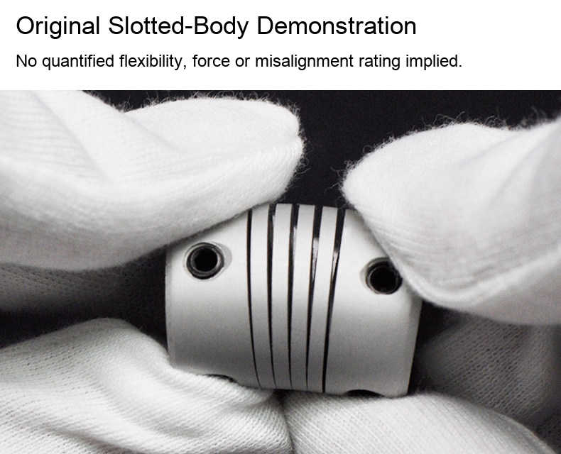
The supplied photographs and drawings show a one-piece slotted aluminum body and the two different shaft-retention arrangements. The source identifies 6061-T6 aluminum, an H7 bore designation and a supplier-listed series operating range of −40 to 100 °C (−40 to 212 °F). These are source-series statements, not an independent material, bore-inspection or temperature-test certificate. Confirm applicability to the actual selected configuration and operating duty. Aerospace certification, electrical insulation, rated torque, maximum speed, zero backlash and numerical misalignment limits are not established.
Selection and Installation
Measure both shafts and select the exact bore pair. Check the body diameter and 25 mm overall length against the available space. Choose the required fixation style rather than ordering by bore pair alone. Align the shafts, keep insertion clear of the flexible slotted section and follow the correct tightening procedure for the actual screws. Isolate the equipment before installation and test the complete assembly before service. No shaft, motor or mounting adapter is included.
Original Drawings and Photographs
The original dimension arrows and product photography are retained without geometry reconstruction or resampling. The source SKU sheet reused one generic image for all styles; this listing instead uses the source's matching set-screw photograph/drawing for D19 and split-clamp photograph/drawing for D20. Photographs illustrate the corresponding style, not a separately verified image of every bore pair or package quantity. The drawing's d1/d2 placeholders remain unchanged; exact selected bores are stated in the model label. Supplier branding, promotional claims and the extra-keyway-price advertisement are excluded. D25L30 options are not added here because that family already has its own link.