TN No-Spring Vacuum Pickup Nozzles and U-Shaped Spring-Loaded Assemblies
TN No-Spring Vacuum Pickup Nozzles and U-Shaped Assemblies
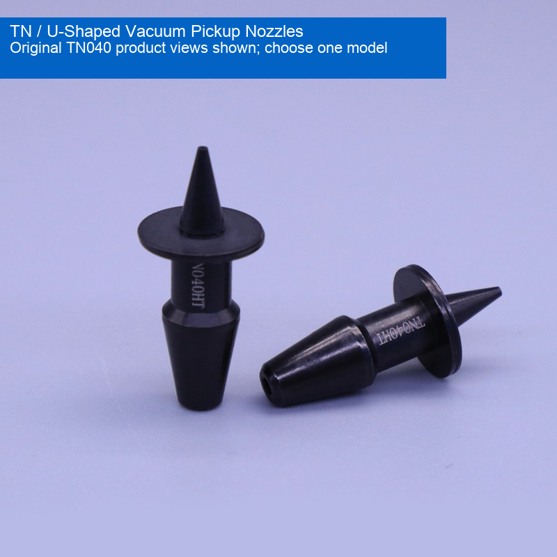
Select one of five TN no-spring pickup nozzles or three U-shaped spring-loaded assemblies. The original photographs show the actual selected configuration. Multi-view and family photographs are reference views, not a two-piece pack or a complete set. These are replacement components for equipment-matched vacuum pickup, not a claim of genuine OEM manufacture or universal machine compatibility.
Models and Tip Dimensions
| Model | Construction | Tip OD | Tip ID |
|---|---|---|---|
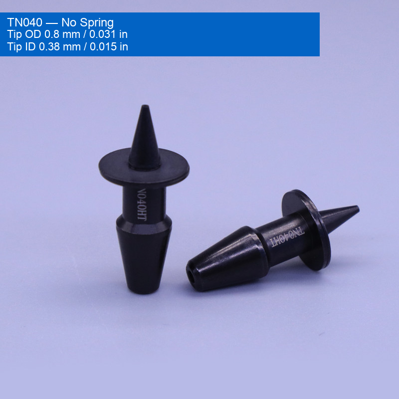
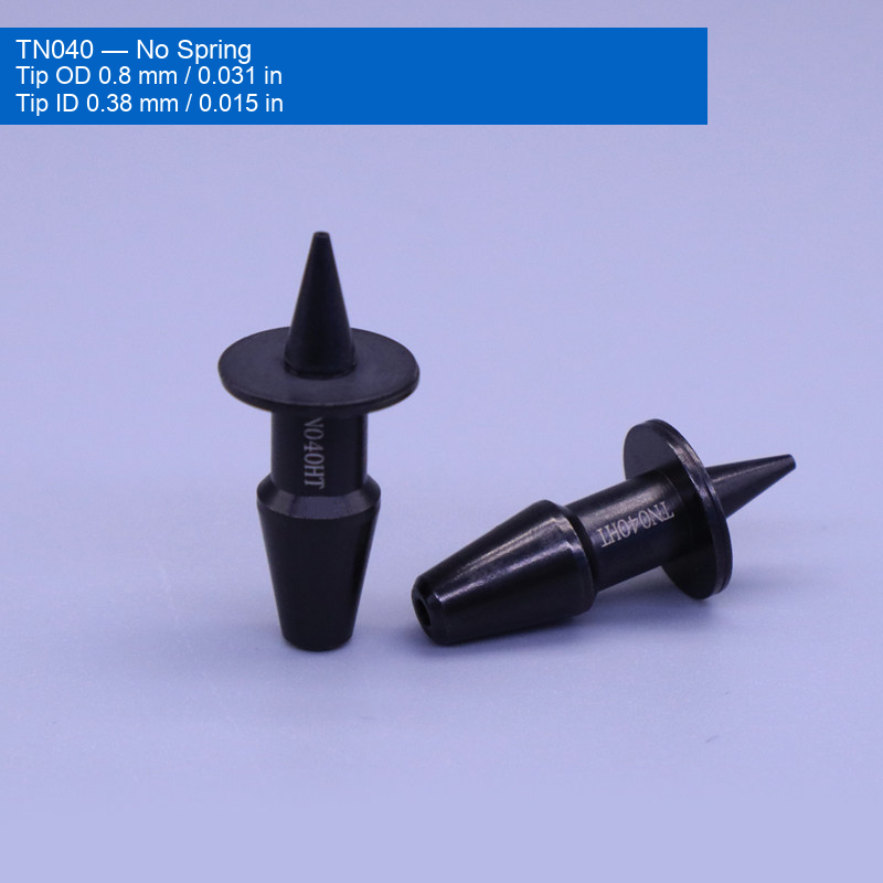
| TN040 | No spring | 0.8 mm / 0.031 in | 0.38 mm / 0.015 in |
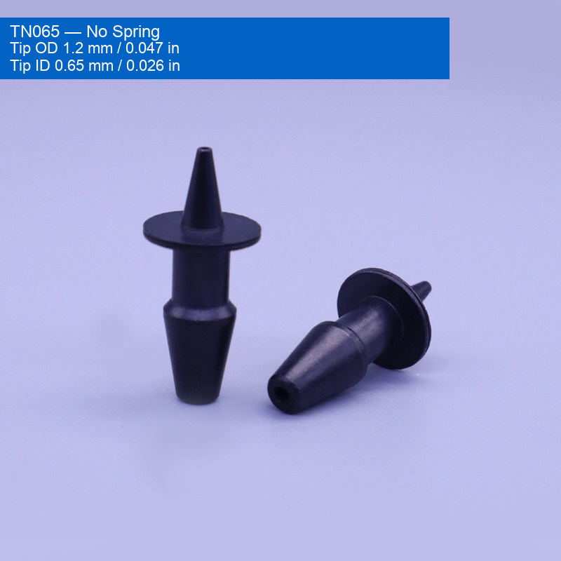
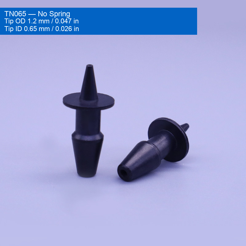
| TN065 | No spring | 1.2 mm / 0.047 in | 0.65 mm / 0.026 in |
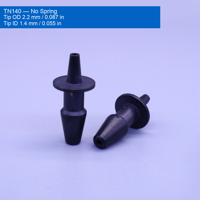
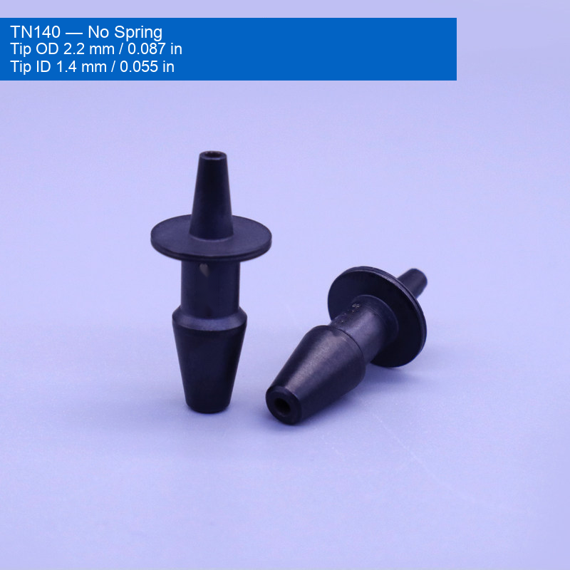
| TN140 | No spring | 2.2 mm / 0.087 in | 1.4 mm / 0.055 in |
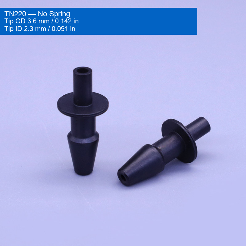
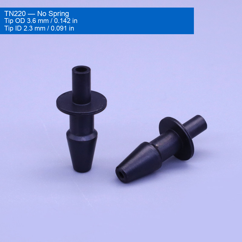
| TN220 | No spring | 3.6 mm / 0.142 in | 2.3 mm / 0.091 in |
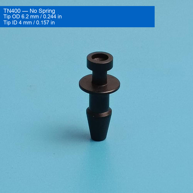
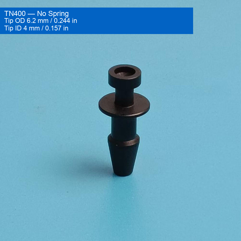
| TN400 | No spring | 6.2 mm / 0.244 in | 4 mm / 0.157 in |
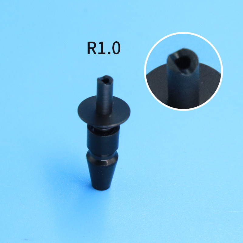
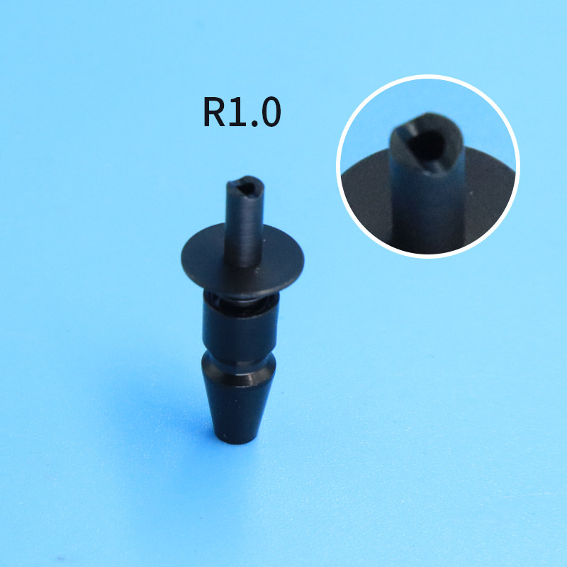
| R1.0 | U-shaped spring-loaded assembly | Not supplied | Not supplied |
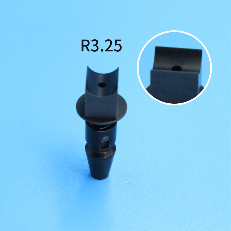
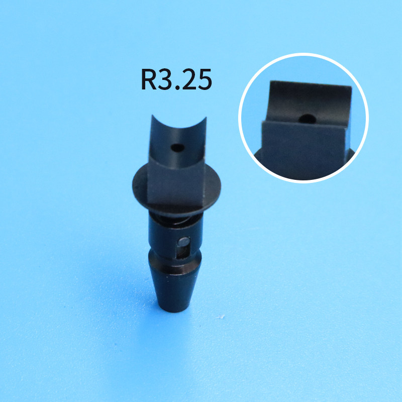
| R3.25 | U-shaped spring-loaded assembly | Not supplied | Not supplied |
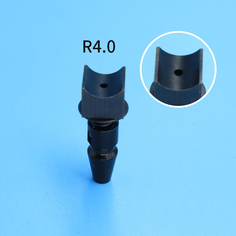
| R4.0 | U-shaped spring-loaded assembly | Not supplied | Not supplied |
TN No-Spring Construction
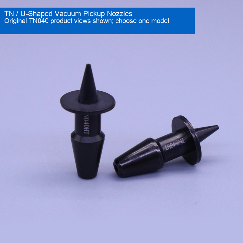
TN040, TN065, TN140, TN220 and TN400 are identified in the source as no-spring steel nozzles. Their original product photographs show the tip, locating flange and lower mounting form. Tip outside and inside diameters are translated directly from the source image. TN220 has a 2.3 mm / 0.091 in tip bore; it must not be substituted with a CN220 drawing or bore dimension. Material grade, coating specification and electrical resistance are not independently established.
U-Shaped Pickup Assemblies
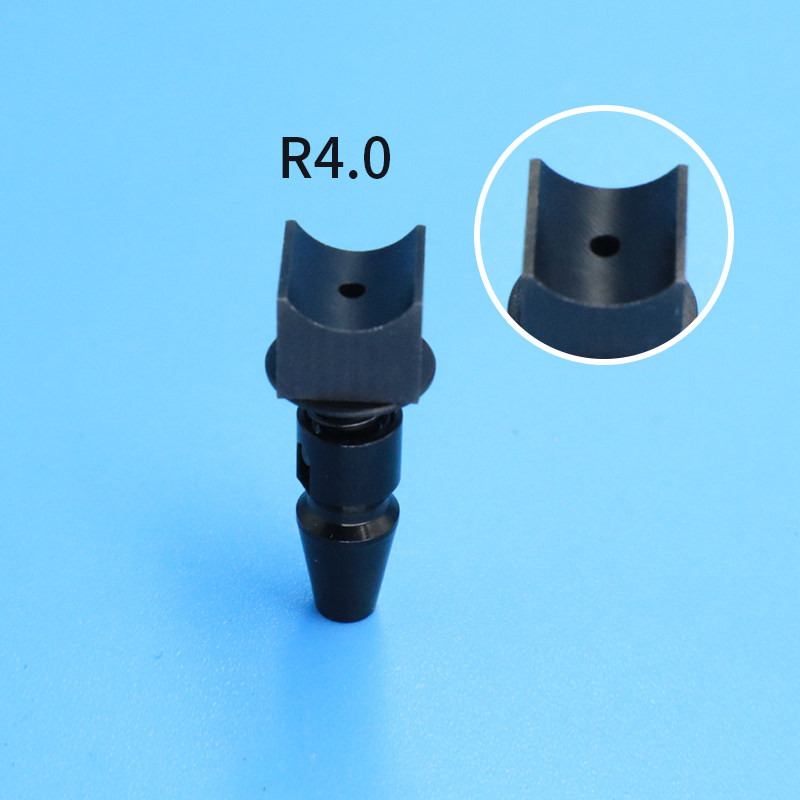
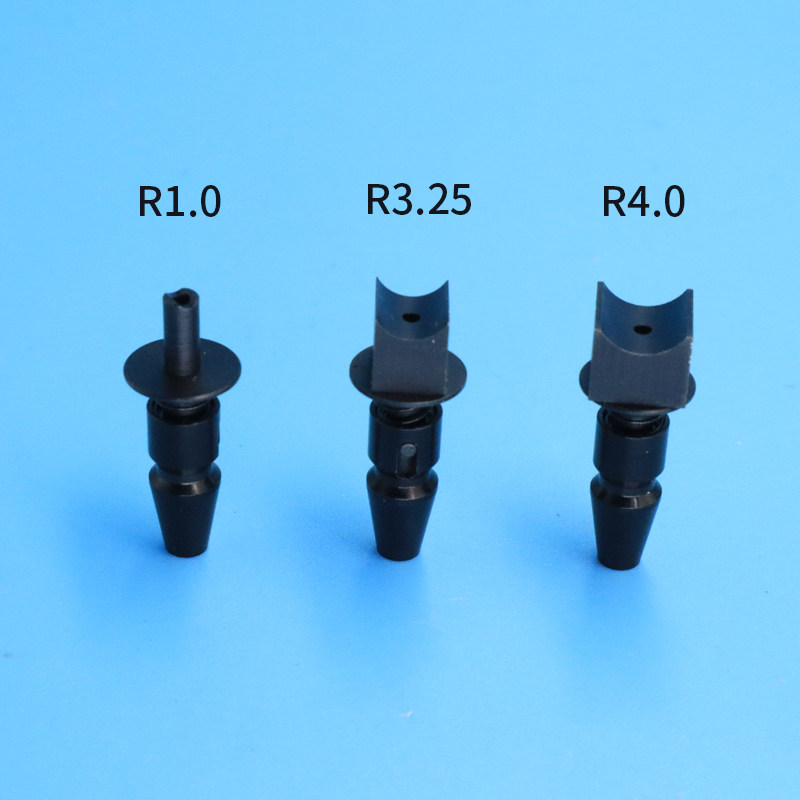
R1.0, R3.25 and R4.0 have different U-shaped tip profiles shown in the original enlarged photographic insets. Their photographs show the lower spring-loaded construction. R values are retained as source model codes only: the source does not establish whether they denote a radius, diameter or another dimension, and no physical inch conversion is inferred from them. Tip and mounting dimensions for these three assemblies are not supplied.
Fit and Application
For vacuum pickup and handling with matching SMT or automation equipment. Check tip contact geometry, bore, nozzle length, flange, mounting taper, holder interface and machine clearance before ordering. The photographs do not prove compatibility with every machine in a manufacturer family. No adapters, holders or CN-series nozzles are included with the TN options.
Installation and Care
Isolate the equipment before installation. Inspect the vacuum passage, tip and locating surfaces for debris, wear or damage. Fit the selected component to its matching holder and verify retention, sealing, pickup and release using the actual workpiece before production. Do not force a mismatched mounting form. Replace damaged or obstructed nozzles.
Supply Scope and Dimensions
One selected nozzle or U-shaped assembly configuration is supplied. Alternative models pictured in family photographs are not included. Inch values are rounded conversions at 25.4 mm per inch and are not manufacturing tolerances. Overall height, mounting tolerances, spring force, temperature rating, ESD performance and pickup force are not supplied; confirm these requirements for the intended process.
Original Product Photographs
The original model photographs and tip close-ups are retained without product reconstruction. Supplier branding and unsupported promotional wording are omitted. Already-listed CN and holder options, generic-photo options and unresolved model conflicts are not duplicated here.
Modell / Konfiguration / SKU
| Modell / Konfiguration | SKU |
|---|---|
| TN040 No Spring — Tip OD 0.8 mm / 0.031 in, ID 0.38 mm / 0.015 in | 3375169505664 |
| TN065 No Spring — Tip OD 1.2 mm / 0.047 in, ID 0.65 mm / 0.026 in | 3375169505666 |
| TN140 No Spring — Tip OD 2.2 mm / 0.087 in, ID 1.4 mm / 0.055 in | 3375169505667 |
| TN220 No Spring — Tip OD 3.6 mm / 0.142 in, ID 2.3 mm / 0.091 in | 3789344054459 |
| TN400 No Spring — Tip OD 6.2 mm / 0.244 in, ID 4 mm / 0.157 in | 3789344054456 |
| U-Shaped Spring-Loaded Assembly — R1.0 | 5505991553756 |
| U-Shaped Spring-Loaded Assembly — R3.25 | 5505991553757 |
| U-Shaped Spring-Loaded Assembly — R4.0 | 5505991553758 |