Non-standard custom manufacturing
Custom Module 1 Nylon Spur Gears — 15–120 Teeth
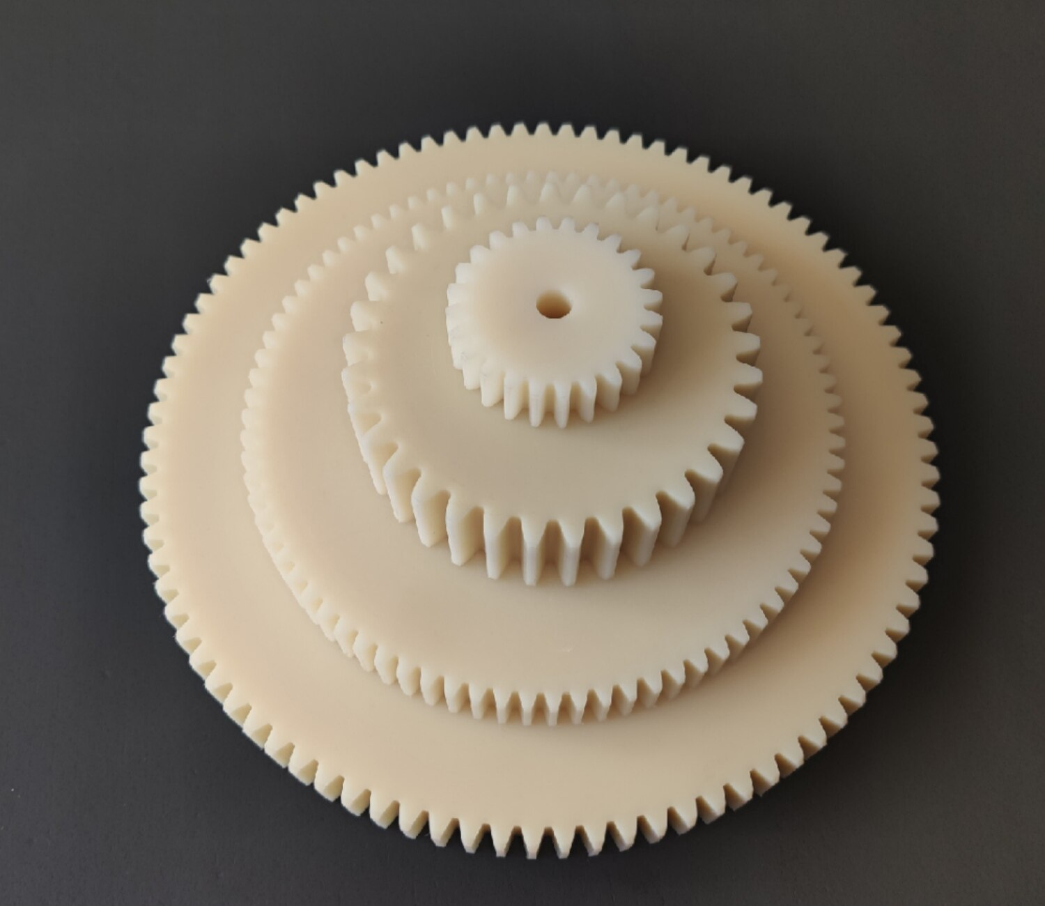
Made-to-drawing module 1 external nylon spur gears with drawing-specific bores, widths and mounting features. Send your drawing or a dimensioned sample specification for a project-specific quotation.
Request a quote. The photographs are manufacturing references, not a ready-to-ship set or a priced pack.
Material, dimensions, tolerances, quantity, finishing, inspection and delivery terms are confirmed in the written quotation before ordering. Direct online purchasing is not available for this custom enquiry listing.
Product and Customization Details
| Product scope | module 1 external nylon spur gears with drawing-specific bores, widths and mounting features |
|---|---|
| Material to confirm | Nylon as stated in the source table; confirm grade and conditioning. MC nylon, PA66, POM, PEEK and PVDF are separate material enquiries, not interchangeable supplied materials |
| Custom features | Drawing-specific dimensions, mounting interfaces, materials and supply configuration |
| Dimensions and quantity | According to your approved drawing and quotation; no fixed pack quantity is implied |
| Ordering method | Send requirements for review and quotation before production |
Specification Notes
The actual source options specify module 1 gears, not a selectable module 2 range. The reference table preserves each stated tooth count, outside diameter and bore. Face width, pressure angle, bore tolerance, keyway, hub profile and accuracy are not defined by those short option labels and must be confirmed on the drawing. The photographs are series references and do not prove the tooth count or size of every illustrated gear. A group photograph is not a multi-piece set. If a different polymer, module or tooth count is required, provide its own drawing for review. No general temperature, load, service-life or accuracy claim is inferred from the promotional text.
Source Reference Specifications
| Source module | 1 mm metric module |
|---|---|
| Source tooth counts | 15, 16, then 20–120 in increments of 5 |
| Source bores | 5 mm for the 15-tooth reference; 6 mm for the other listed references |
| Material selection | Confirm exact polymer grade. Color does not establish material properties |
Reference values require confirmation for the selected drawing. Reference data are not independently certified ratings or a universal compatibility claim.
Information Needed for Your Quotation
- PDF or CAD drawing with units, revision, all dimensions and the required quantity for each part.
- Exact material grade and condition. Identify any material certification or traceability requirement.
- Critical fits and tolerances, datum references, surface roughness, holes, threads and edge requirements.
- Any heat treatment, coating, plating, polishing or other secondary operations required.
- Required inspection documents, packaging, delivery destination and requested schedule.
Reference Photographs
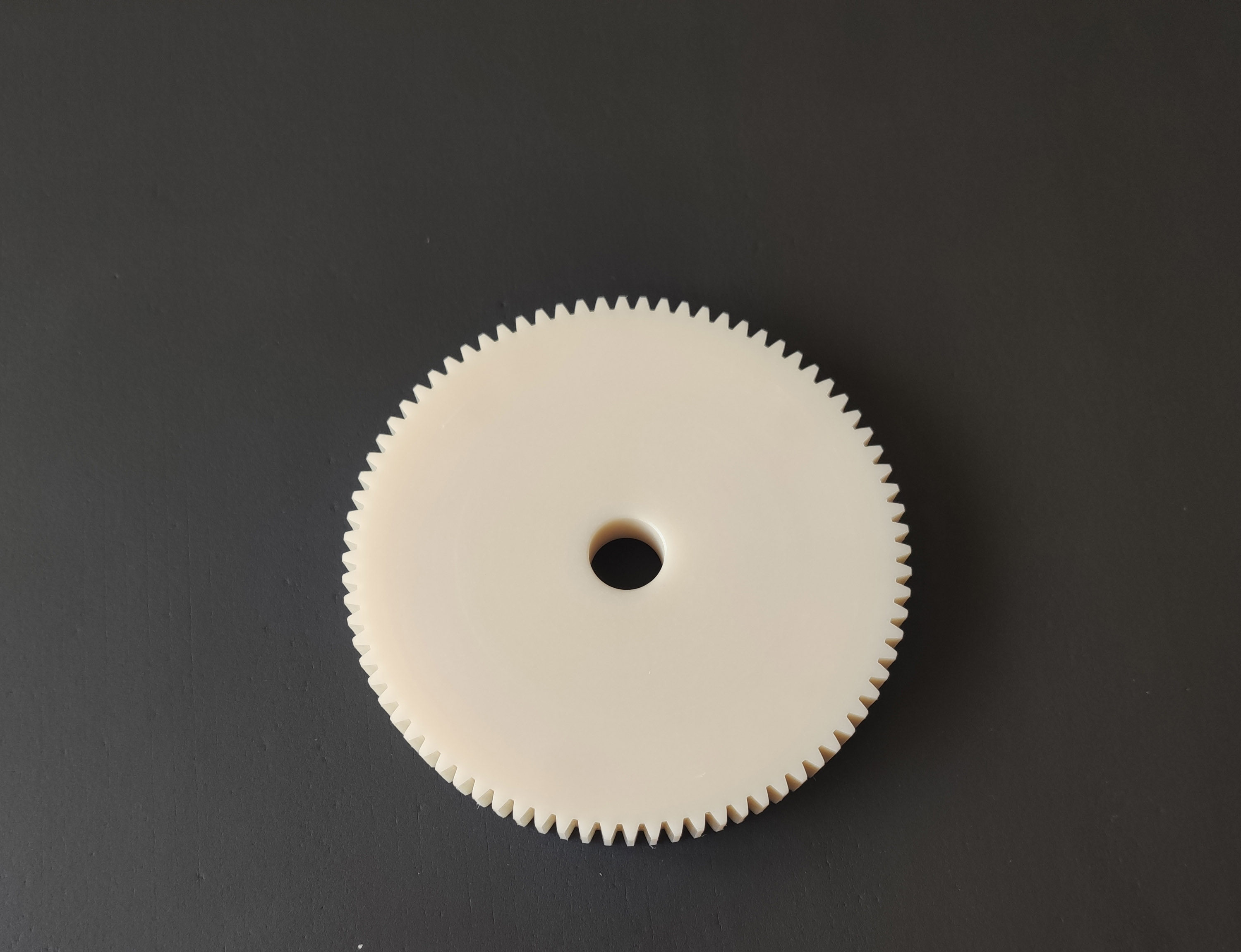
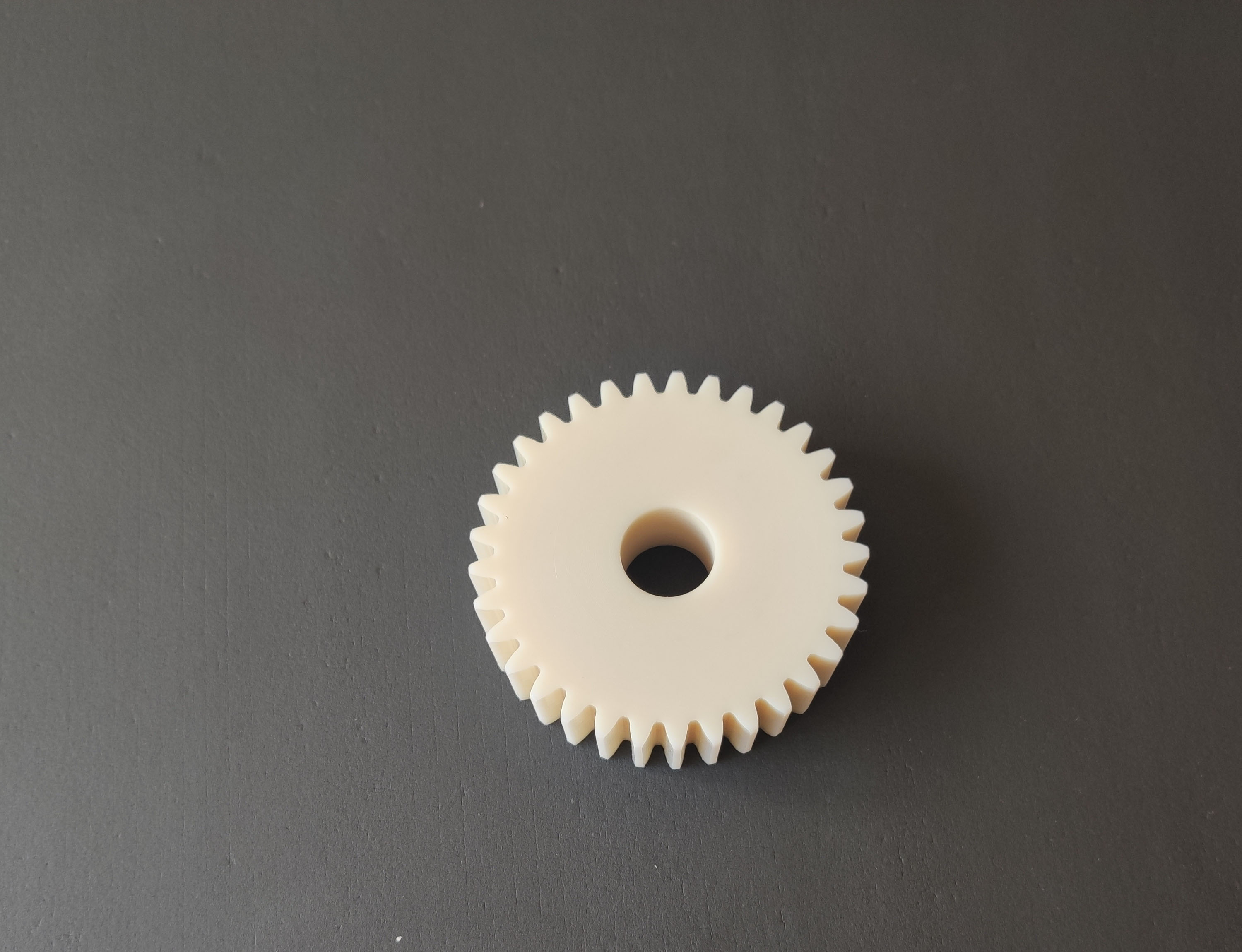
These original photographs illustrate shapes and machining examples. They do not establish exact dimensions, material grades, tolerances, included quantities or current stock. The delivered part follows the approved drawing and written order specification.
Review and Production Workflow
- Send the drawing or sample requirements, material and quantity.
- Review manufacturability and confirm unresolved dimensions, fits and finishes.
- Approve the written quotation and the final drawing revision.
- Confirm any first-article or inspection requirements before production.
Production, delivery, acceptance and custom-order terms are agreed in the quotation. No fixed lead time, universal tolerance or application certification is implied by the reference images.
Module 1 Source Size References
Dimensions follow the source option names. Inch conversions are rounded to three decimals; mm values govern. Confirm face width and all unlisted mounting details on the drawing.
| Module (mm) | Teeth | Outside diameter (mm / in) | Bore (mm / in) |
|---|---|---|---|
| 1 | 15 | 17 / 0.669 | 5 / 0.197 |
| 1 | 16 | 18 / 0.709 | 6 / 0.236 |
| 1 | 20 | 22 / 0.866 | 6 / 0.236 |
| 1 | 25 | 27 / 1.063 | 6 / 0.236 |
| 1 | 30 | 32 / 1.260 | 6 / 0.236 |
| 1 | 35 | 37 / 1.457 | 6 / 0.236 |
| 1 | 40 | 42 / 1.654 | 6 / 0.236 |
| 1 | 45 | 47 / 1.850 | 6 / 0.236 |
| 1 | 50 | 52 / 2.047 | 6 / 0.236 |
| 1 | 55 | 57 / 2.244 | 6 / 0.236 |
| 1 | 60 | 62 / 2.441 | 6 / 0.236 |
| 1 | 65 | 67 / 2.638 | 6 / 0.236 |
| 1 | 70 | 72 / 2.835 | 6 / 0.236 |
| 1 | 75 | 77 / 3.031 | 6 / 0.236 |
| 1 | 80 | 82 / 3.228 | 6 / 0.236 |
| 1 | 85 | 87 / 3.425 | 6 / 0.236 |
| 1 | 90 | 92 / 3.622 | 6 / 0.236 |
| 1 | 95 | 97 / 3.819 | 6 / 0.236 |
| 1 | 100 | 102 / 4.016 | 6 / 0.236 |
| 1 | 105 | 107 / 4.213 | 6 / 0.236 |
| 1 | 110 | 112 / 4.409 | 6 / 0.236 |
| 1 | 115 | 117 / 4.606 | 6 / 0.236 |
| 1 | 120 | 122 / 4.803 | 6 / 0.236 |
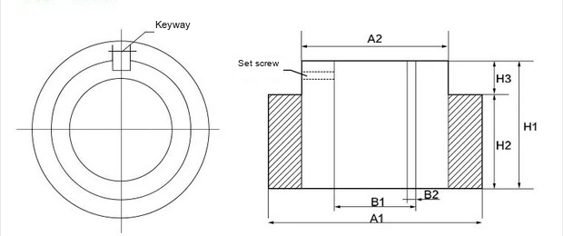
The machining diagram preserves A1/A2, B1/B2, H1/H2/H3 and the keyway/set-screw features as dimension labels, not assigned sizes. Send the required values and tolerances for your own part.