A pressure gauge can show the desired setting while an actuator still responds poorly during a cycle. Assess the regulator under flow, not only at rest. Use the complete regulator model and tubing configuration when comparing a compact pressure-control installation.
1. Write the pressure requirement at the load
Specify the downstream operating pressure, expected flow demand and the lowest available supply pressure during production. Include simultaneous consumers on the same branch. A regulator cannot be assessed from the unloaded gauge reading alone.
Locate the gauge and distinguish its reading from pressure at a distant cylinder or tool. Long tubing and restrictive fittings remain part of the installation.
2. Check static and operating conditions
Record pressure before the actuator starts and during its highest demand. A difference can involve the regulator, supply capacity or downstream restrictions. Do not compensate immediately by increasing pressure beyond the component or machine limits.
Ask for model-specific flow characteristics when selecting a replacement. Compare candidates under the same inlet pressure, downstream setting and flow conditions.
3. Read the ARM5SA suffix correctly
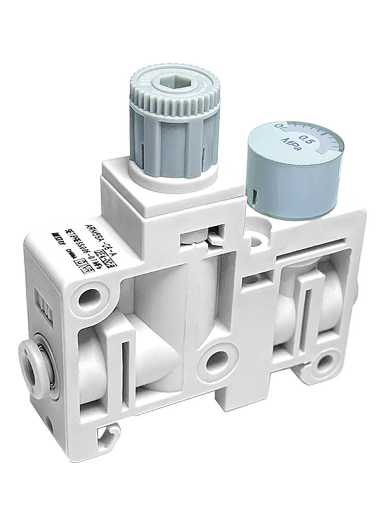
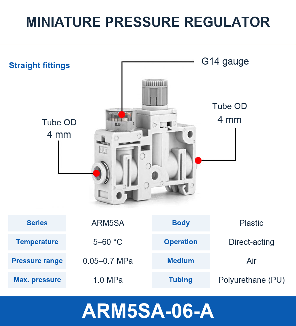
The linked ARM5SA range has straight and elbow fitting versions. Its model identifiers do not directly equal the tube outside diameter: use the product's separate connection table and selected drawing.
Confirm air as the operating medium and check the exact listed pressure and temperature limits. These compact pneumatic selections should not be presented as suitable for another gas or liquid without written confirmation.
4. Separate regulation from isolation
A regulator controls pressure; it should not be presumed to provide a reliable shutoff, dump function or safety limit. Check the actual circuit for the machine's approved isolation and exhaust arrangements.
Before service, stop motion, support loads and follow the site's energy-isolation procedure. Turning the adjustment knob down is not proof that trapped downstream pressure has been removed.
5. Commission one controlled change at a time
Inspect tubing, port direction, gauge placement and mounting clearance before adjustment. Start with the machine manufacturer's commissioning procedure, then observe the full cycle at the approved settings. Check that the adjustment remains accessible without entering a moving mechanism.
Log the setting, supply conditions, operating pressure and cycle result. If the issue persists, compare upstream and downstream measurements rather than repeatedly raising the setpoint.
6. Keep the replacement file useful
Save the complete regulator code, fitting orientation, tube OD, gauge configuration and circuit location. Include a photograph showing the installed connections, not only a close-up of the knob.
For troubleshooting, provide the pressure trace, demand sequence and whether other equipment shares the supply. This information makes a meaningful selection possible without guessing from regulator body size.
7. Related products and next steps
ARM5SA regulators · Pneumatic connection fittings.
Send the complete model code, drawings or photographs, required quantity and application conditions to boltte@boltte.com. Confirm missing specifications in writing before ordering. Catalogue images illustrate the linked product family; they are not proof of compatibility, tested capacity or certification for your installation.
8. Further technical reading
These manufacturer references explain general engineering principles. Their product ratings, test results and installation values do not apply automatically to BOLTTE selections.