Sheet metal looks easy to grip because it is usually broad and relatively smooth. In production, however, oil film, stamping texture, cutouts, sharp edges, panel flex and rapid robot motion can turn a stable bench test into intermittent pickup failures. A reliable selection therefore starts with the workpiece and motion profile—not only the nominal diameter of the vacuum cup.
1. Map the real pickup zone
Mark every hole, slot, embossed feature, weld, edge radius and surface transition inside the proposed cup locations. The complete sealing lip must remain on a continuous surface throughout the cycle. A cup that overlaps a laser-cut hole or approaches an edge may leak even when most of its area is supported.
Also check part-to-part variation. Thin panels can bow differently in a stack, and stamped parts may sit at changing heights. If the pickup zones are not coplanar, use compliant mounts or spring-loaded holders so the cups can contact without forcing the panel out of shape.
2. Identify oil, coating and surface texture
Press oil can reduce friction, attract particles and change how the sealing lip behaves. Painted, galvanized, brushed or textured sheet can also increase leakage. Do not assume that a high vacuum reading at a stationary test point guarantees resistance to sliding during acceleration.
- Dry, smooth sheet: usually offers the most predictable seal.
- Oily sheet: requires material-compatibility checks, conservative friction assumptions and cleaning control.
- Textured or scratched sheet: may need a softer lip, a different profile or more available flow.
- Hot sheet: requires confirmation of cup material, fitting, tubing and nearby component temperature limits.
3. Choose the cup profile for stability
A flat cup is normally the first profile to evaluate on a rigid, flat panel because it has low internal movement and can resist lateral acceleration better than a highly compliant profile. Bellows cups can compensate for height variation and gentle curvature, but their flexibility may allow more tilt or lateral movement. Use only as much compliance as the application needs.
Large-diameter heavy-duty cups can provide more theoretical holding force, but larger is not automatically safer. The lip must stay away from holes and edges, the panel must support the cup without excessive deflection, and the evacuation volume must still meet the required cycle time.
4. Select material for the environment
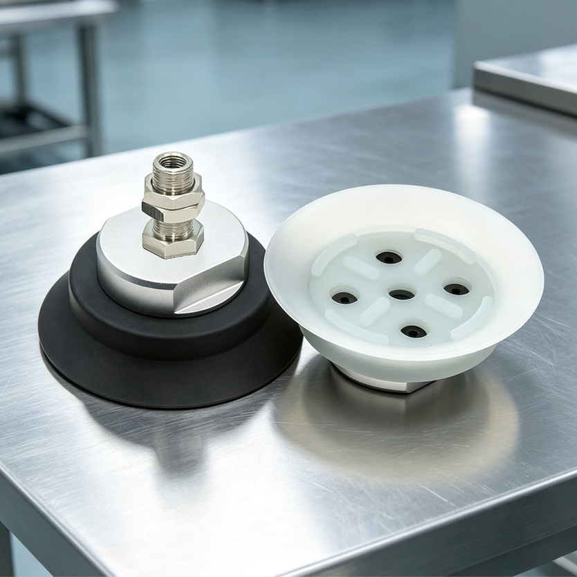
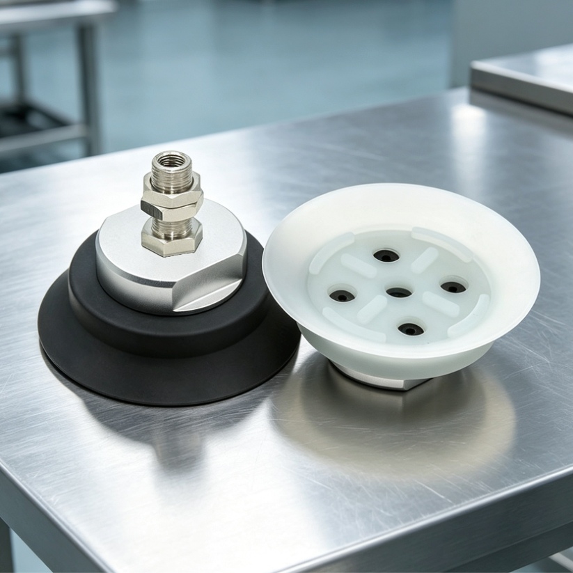
For the listed ZPT heavy-duty vacuum cups, HS is identified as white silicone and HN as black nitrile rubber. Treat those as separate material options and confirm the selected model image and drawing before ordering.
Nitrile rubber is often evaluated where oil resistance and abrasion behavior matter. Silicone is often evaluated where flexibility or a wider temperature range is important. Actual suitability depends on the specific oil, coating, temperature, surface-marking requirement and duty cycle. Test the real material rather than selecting from color alone.
5. Calculate force, then add real derating
The theoretical normal holding force starts with F = Δp × A. Divide the total requirement among the cups that can reliably share the load, then apply a safety factor and include vertical acceleration, deceleration and emergency-stop conditions. Our holding-force and cup-diameter guide explains the calculation in detail.
For vertical panels, gravity acts parallel to the surface, so resistance depends strongly on friction. Oil, vibration and uneven cup loading can sharply reduce usable capacity. Use conservative test data, consider mechanical support, and do not treat the theoretical pressure-area result as a safe vertical-load rating.
6. Design the cup layout around panel stiffness
Distribute cups to control bending and rotation. A wide, symmetric layout generally supports thin sheet better than concentrating all cups near the center. Keep the center of gravity inside the support polygon, and leave clearance for clamps, dies, weld fixtures and downstream operations.
Do not assume equal load sharing. If one corner of a sheet lifts first, one or two cups may carry most of the initial load. Independent compliance, vacuum monitoring or zone control can make the system more tolerant of height variation and a missed pickup point.
7. Check flow, evacuation time and release
Measure vacuum at the cup during the real cycle. Long tubing, small fittings, shared manifolds and high internal cup volume can delay pickup. A pump or generator must provide enough flow to overcome normal leakage and reach the switching threshold before motion begins.
Release performance matters too. Thin panels may remain attached because of residual vacuum or oil adhesion. Confirm blow-off settings, valve response and safe part separation without denting or marking the sheet.
8. Run a production-speed validation
- Test the cleanest and oiliest expected parts.
- Include warped, scratched and edge-of-tolerance panels.
- Record vacuum build time and minimum vacuum during acceleration.
- Verify the response to one missed cup or a partially covered hole.
- Inspect sliding, panel deflection, surface marks and cup wear.
- Repeat at normal speed, emergency stop and worst-case orientation.
Selection checklist
- Sheet material, thickness, mass and temperature
- Surface finish, oil type and contamination level
- Pickup-zone dimensions, holes, edges and curvature
- Motion direction, acceleration, deceleration and cycle time
- Target vacuum at the cups and available flow
- Cup profile, material, diameter and quantity
- Mounting compliance, tubing, valves and vacuum monitoring
For application support, send the sheet size, weight, surface condition, pickup drawing, motion profile, target vacuum and preferred mounting interface through the BOLTTE application RFQ. Final selection must be verified on the actual workpiece and machine; do not use a basic catalog estimate as the sole safeguard for personnel or suspended loads.