Glass and other smooth panels can produce an excellent vacuum seal, but the application still demands careful engineering. Surface marks, edge proximity, panel flex, coating compatibility, uneven load sharing and vacuum loss can create risks that are not visible in a simple stationary pickup test. The correct cup is part of a complete handling system that includes layout, monitoring and a validated response to faults.
1. Define the panel and the handling risk
Record the panel dimensions, mass, thickness, coating, surface finish, temperature and permissible contact zones. Identify whether the part is lifted horizontally, tilted, rotated or transported vertically. A vertical panel relies heavily on friction between the cup and surface, while a horizontal pickup is governed more directly by the pressure difference and effective sealed area.
Glass breakage can cause serious injury. Use guarding, exclusion zones, vacuum monitoring and mechanical retention appropriate to the machine risk assessment. Never rely on a single cup or a basic catalog-force calculation as the only safeguard for an overhead or personnel-exposed load.
2. Keep the complete sealing lip on a stable surface
Locate cups away from edges, holes, printed areas, labels, seams and strong curvature. The entire lip must contact a continuous surface. Edge distance should account for placement tolerance, panel movement and cup deformation—not only the nominal drawing location.
For thin or flexible panels, distribute cups so the glass or sheet remains supported without excessive bending. A large cup can provide more area, but it may cross a curved region or concentrate stress if the panel is not sufficiently flat.
3. Choose a profile with controlled movement
Flat profiles are commonly evaluated on smooth, flat panels because they offer low internal movement and good positioning stability. A bellows profile can help when the pickup surface has gentle curvature or the contact points are at different heights, but additional compliance can allow more tilt and lateral movement.
If height variation is caused by the machine rather than the panel, a flat cup on a spring-loaded holder may provide better stability than adding unnecessary bellows. Match compliance to the real source of misalignment.
4. Evaluate cup material and surface marking
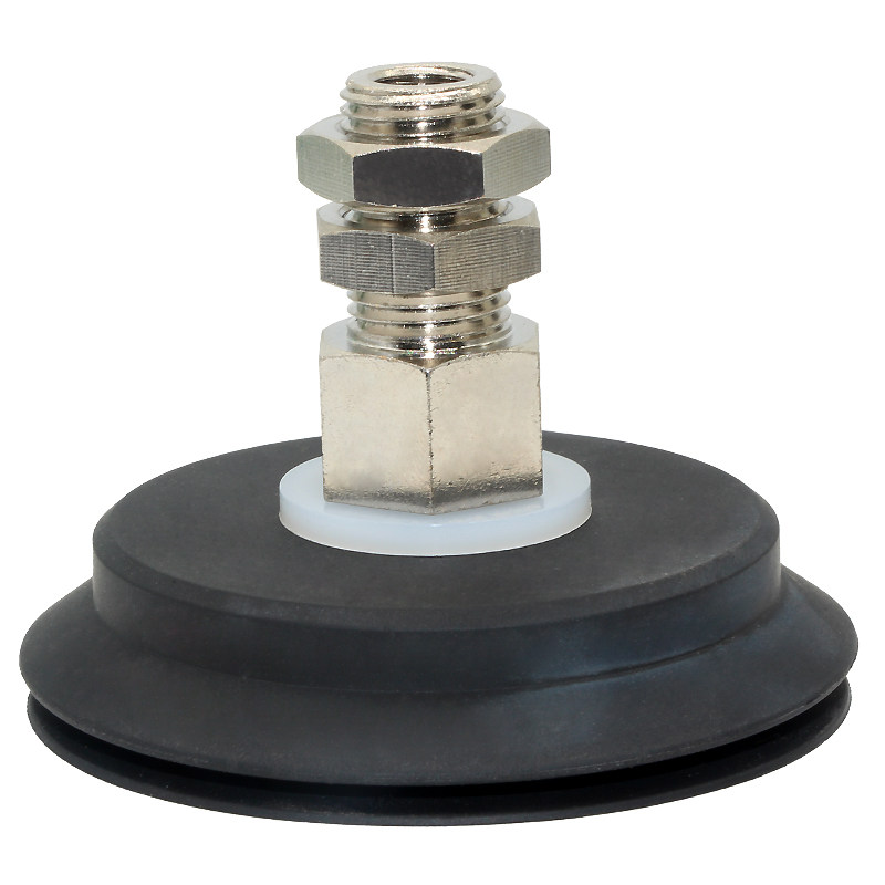
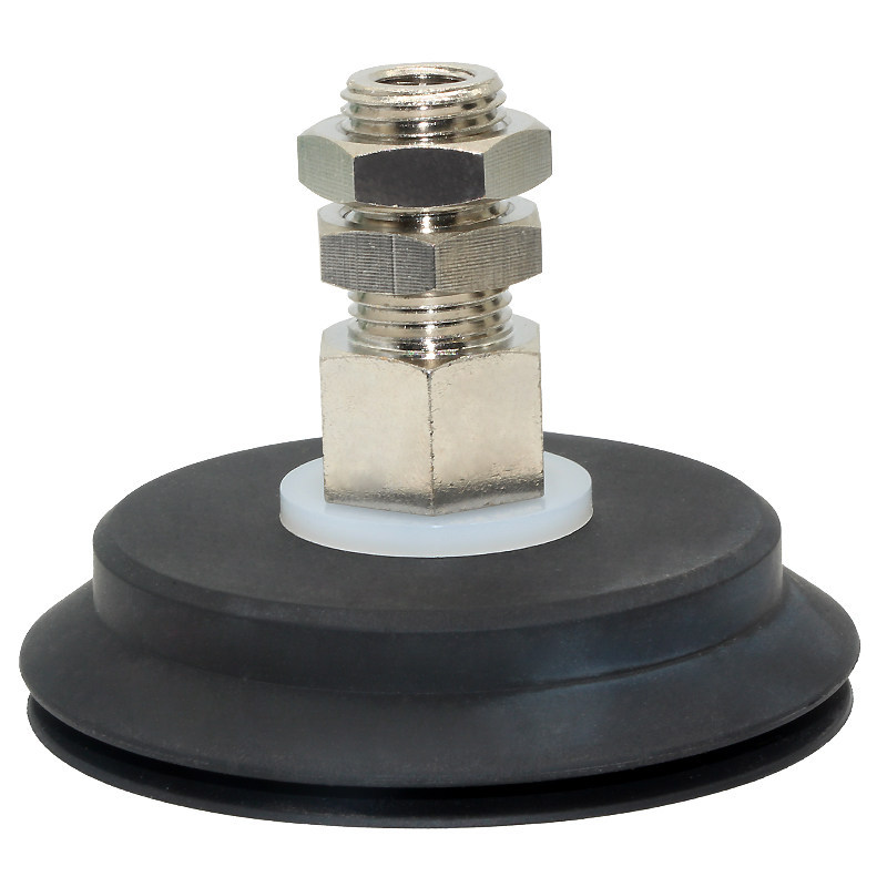
The listed PJTK vacuum cup assemblies offer white silicone or black nitrile-rubber options in 60, 70 and 80 mm nominal diameters. Material selection should consider surface marking, coating compatibility, temperature, abrasion, cleaning agents and the required service life.
Silicone is often evaluated for flexibility and temperature range, while nitrile rubber is often evaluated for wear and oil resistance. Neither description guarantees suitability for every coated, optical or decorative panel. Run a mark test on the actual production surface after realistic contact time, load, temperature and cleaning conditions.
If the handling setup calls for a compatible cup cover, review the black antistatic vacuum cup covers, 15–50 mm. This listing supplies covers only, not complete vacuum cup assemblies. Confirm fit, vacuum performance and marks on the actual panel; the product name alone does not establish a certified ESD rating or compatibility with every coating.
5. Size the cup from required force—not panel area alone
For normal lifting, theoretical force begins with F = Δp × A. Use the effective sealing area and vacuum measured at the cup, then apply a safety factor and include acceleration, deceleration, tilt and uneven load sharing. Round up to an available model only after checking that the complete lip fits within the approved pickup zone.
When the panel is vertical, the load acts parallel to the surface and friction becomes critical. Dust, moisture, oil, protective film and vibration can reduce sliding resistance. Use tested friction data or conservative production trials, and add mechanical support where the consequence of sliding is significant.
6. Use multiple cups and plan for uneven loading
Arrange cups around the center of gravity with enough spacing to control rotation and panel flex. Avoid layouts in which one cup contacts first and temporarily carries most of the weight. Independent spring compensation can improve contact when the tooling and panel are not perfectly parallel.
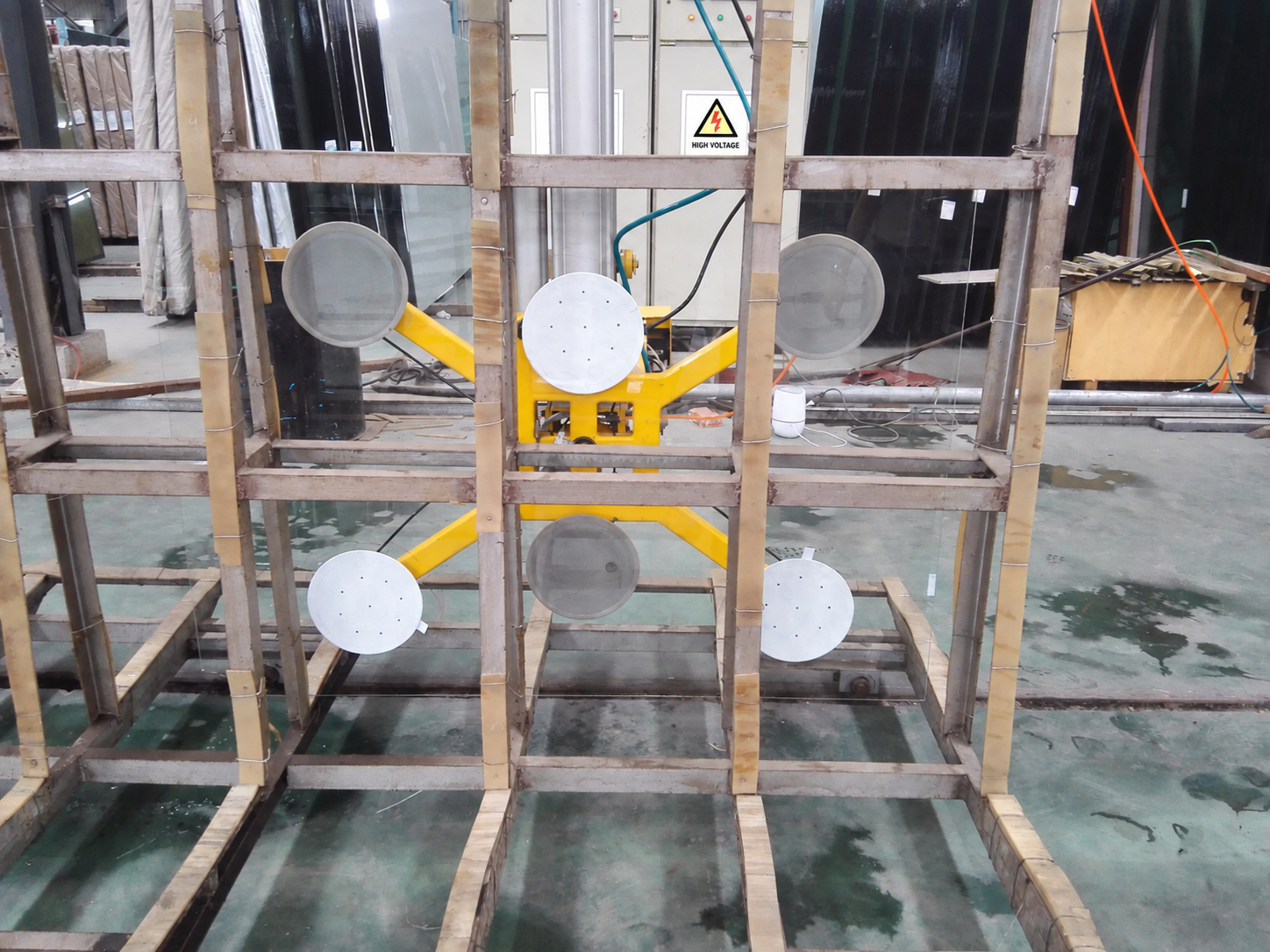
For large panels, divide the system into monitored zones when appropriate. A missed cup should be detected before full-speed motion. The machine should have a defined safe response to low vacuum, excessive evacuation time, a broken line or an unexpected loss of power.
7. Control cleanliness without damaging the cup
Particles between the lip and glass can create leakage or marks. Establish inspection and cleaning intervals based on the real environment. Use only cleaning methods compatible with the cup material and panel coating. Aggressive solvents, sharp tools and abrasive wiping can damage the sealing lip.
Inspect for cracks, cuts, hardening, permanent deformation and contamination. Replace cups before wear creates unstable pickup performance. Also inspect fittings, tubing, silencers, filters and vacuum switches; the cup is only one part of the pneumatic path.
8. Validate the complete cycle
- Test minimum and maximum panel sizes and thicknesses.
- Include coated, dusty, wet or protective-film samples when they can occur.
- Measure evacuation time and minimum vacuum during tilt and acceleration.
- Inspect for marks after the longest realistic contact time.
- Confirm release time and that the panel does not cling after venting.
- Verify the machine response to one missed cup and simulated vacuum loss.
Information to send for model selection
- Panel material, dimensions, mass and thickness
- Surface coating, protective film and marking limits
- Approved pickup zones and edge clearances
- Horizontal, vertical or tilting motion
- Acceleration, cycle time and target vacuum
- Number of cups, layout and mounting interface
- Temperature, contamination and cleaning process
Send these details and a panel drawing through the BOLTTE application RFQ. We can help narrow the model options, but the machine builder remains responsible for final testing, guarding, monitoring and compliance with the applicable safety requirements.
Fabric Covers for Glass and Solar Panels: Diameter and Hole Pattern
For a compatible vacuum cup requiring a removable fabric contact layer, compare the 12-300 mm non-marking vacuum cup fabric covers. This product supplies covers only; cups, holders and fittings are not included.
- Match the selected cover size to the actual cup face and check how the cover is retained.
- Check the center opening and the number and positions of other holes. The listed 60 mm center-hole and multi-hole options are separate selections.
- Use the exact variant photograph and size reference, not the family image alone. The product page lists all 27 model options and their SKU references.
- Test sealing, release, contact marks and the complete handling cycle on the actual glass, mirror or photovoltaic panel. A "non-marking" product name does not guarantee the result on every coating.
For compatibility assistance, send the cup-face photograph, selected model or SKU, diameter, hole layout, surface finish, quantity and delivery country to boltte@boltte.com.