A coupling connects two shafts, but matching the outside diameter is only one small part of selection. The two bore interfaces, fastening method, installation length and operating requirements must agree with the drive. Similar-looking couplings may have different internal construction or limits, so a photograph cannot establish interchangeability.
This guide explains a purchasing and engineering-review sequence for BOLTTE shaft couplings. It uses the current CPB/CPBC bellows and rigid coupling listings as examples. It does not assign universal torque, speed or misalignment ratings to those ranges; obtain the data for the actual configuration before approving the application.
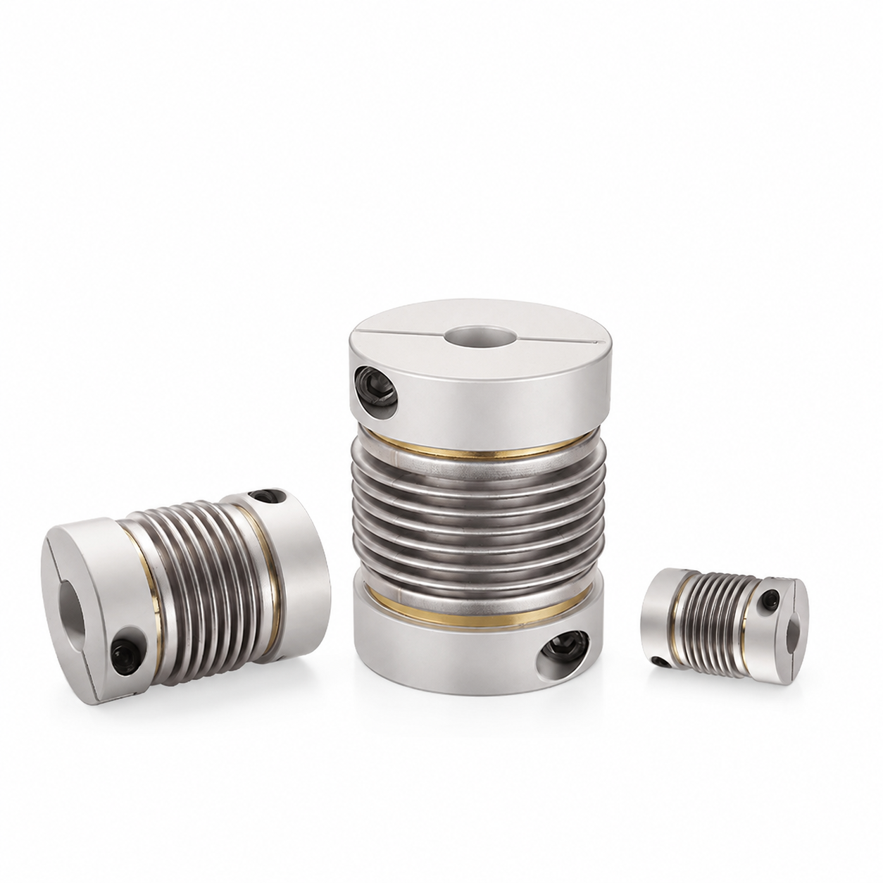
1. Define the drive before choosing a model
Record the driving and driven equipment, both shaft diameters, normal and maximum speed, operating torque and any start-stop or reversing duty. Explain whether the system is moving a load, measuring position or transmitting intermittent motion. The required relationship between the shafts matters as much as their diameters.
Include the available axial space, surrounding clearance and access for installation. Identify expected temperature changes, vibration and environmental exposure. If the requirements are not yet known, ask the machine designer to provide them. Ordering from a bore size alone can produce a component that fits physically but has not been reviewed for the actual operating conditions.
2. Distinguish rigid and flexible constructions
The BOLTTE aluminum rigid coupling range and CPB/CPBC bellows range are different constructions. Select a rigid connection only with a suitably aligned shaft arrangement. A bellows element should not be treated as permission to ignore alignment.
The CPB/CPBC listing describes aluminum hubs with a stainless-steel bellows section. Its listed outer diameters run from 16 to 65 mm. Those product facts identify a family; they do not define a rating for every size. Review the allowed movement and load for the chosen model, and do not assume that a larger outside diameter alone guarantees the required performance.
3. Specify both finished bores and interfaces
State D1 and D2 independently, with the relevant shaft dimensions and tolerance or fit requirement. If a keyway, D-flat, spline or other interface is needed, identify it explicitly and provide its dimensions. Equal nominal shaft diameters do not eliminate the need to check the complete connection.
For a replacement order, measure the mating shafts rather than a worn bore whenever the approved maintenance process permits. Supply a drawing of shoulders, spacers and nearby bearing positions that affect assembly. Check whether the selected option is a finished coupling, an add-on machining item or a custom enquiry. An option describing a keyway is not automatically a complete additional coupling.
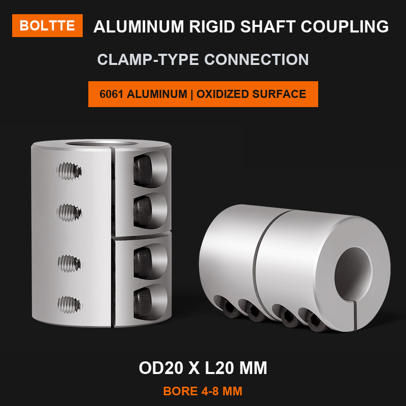
4. Choose clamp or set-screw fastening deliberately
Within the audited bellows range, CPBC denotes clamp hubs and CPB denotes set-screw hubs. The listing includes CPBC Clamp and CPB Set-Screw configurations with the same OD 16 × L 27 mm envelope. They remain different fastening choices, even where the outside dimensions appear identical.
Check access for the fasteners and the manufacturer's instructions for the chosen arrangement. Confirm insertion depth, shaft surface requirements and tightening procedure. Use the specified tightening torque for that component; do not borrow a value from another coupling brand or estimate it from screw appearance. Before servicing a drive, follow its isolation procedure and prevent unexpected rotation.
5. Review alignment and combined movement
Describe axial, angular and parallel offset separately. Also explain whether they happen together, change with temperature or occur only during installation. A catalogue maximum for one movement should not be assumed to apply simultaneously with all other maximum movements. The permitted combinations must come from the selected coupling's documentation.
KTR's coupling selection questionnaires provide a general reference for collecting application requirements. Its TOOLFLEX assembly instructions also illustrate why alignment and combined displacement need model-specific review. Neither source establishes BOLTTE product ratings or direct replacement compatibility.
6. Confirm the installation and acceptance plan
Inspect the supplied part, bore interfaces and fastening arrangement against the approved order. Verify the axial position and clearance through the intended machine movement. Keep the flexible element free from unintended contact, distortion or unsupported assembly loads. Do not use the coupling to pull an incorrectly positioned shaft into place.
Commission the guarded drive under the machine's approved procedure, checking noise, vibration, fastening security and application performance. Record alignment and inspection results where required. If abnormal behaviour appears, stop and investigate the cause before increasing speed or load. Acceptance should cover the complete drive, including bearings and supporting structure, rather than the coupling in isolation.
7. Send a complete coupling enquiry
Provide both bores and shaft details, coupling family, fastening preference, available envelope, torque, speed, duty cycle and each type of expected movement. Include material or corrosion requirements and the requested inspection documents. Photographs are useful context, but dimensioned drawings are needed for critical interfaces.
If a catalogue option does not match, review our custom shaft coupling enquiry page and email the drawing to BOLTTE. Confirm feasibility, finished bores, operating limits and the written quotation before approving custom production. A custom example image is not a performance specification or a ready-to-ship assembly.
Common ordering question
Does a bore range mean the two bores are already finished?
Not necessarily. Read the exact model and ordering instructions. A listed bore range describes the supported selection or machining range; the finished D1 and D2 dimensions still need confirmation. Ask what will be supplied before purchase. Keep that confirmation with the order, especially when the two shaft sizes differ. Also distinguish a machining add-on from a complete coupling: selecting an add-on should not be interpreted as ordering a second physical component. A clear part list prevents this ambiguity when procurement and engineering are handled by different people.