GY / GYS / GYH 45-Steel Rigid Flange Couplings
Made-to-order flange couplings with listed model prices. Select the series and body size, then provide the finished dimensions required for both shafts. The bore values in the options are machining ranges, not a supplied fixed bore pair.
Ordering Requirements
Provide d1 and d2, the bore tolerance, shaft engagement lengths, keyway dimensions and any special drawing requirements in Order requirements or contact BOLTTE with the drawing. We will confirm the manufacturing specification before production. Do not interpret, for example, a 12–19 mm range as a 12 × 19 mm finished coupling. Changes outside the listed model scope require confirmation before ordering. No fixed production lead time is promised.
Series Construction
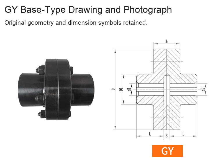
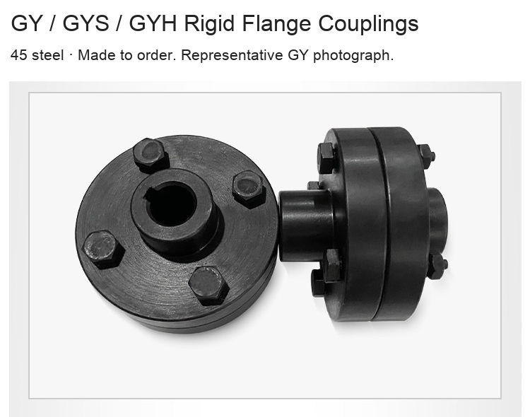
- GY: base-type rigid flange coupling.
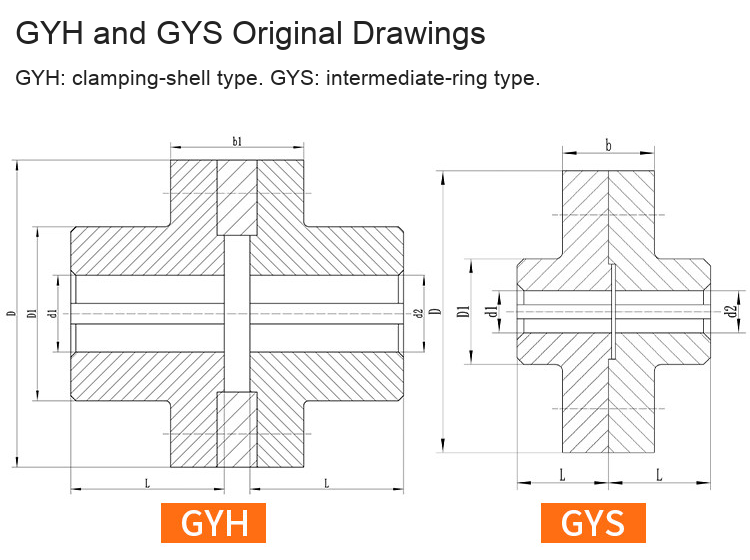
- GYS: intermediate-ring type.
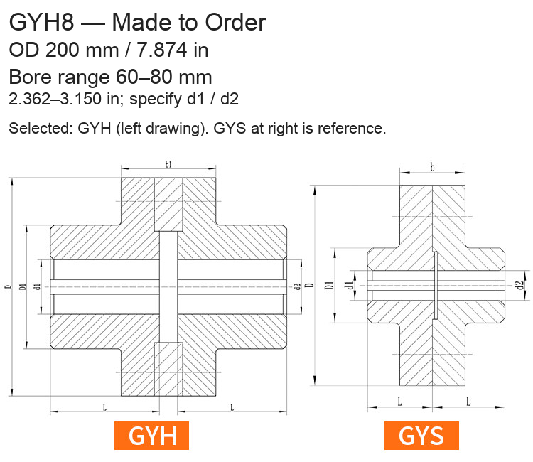
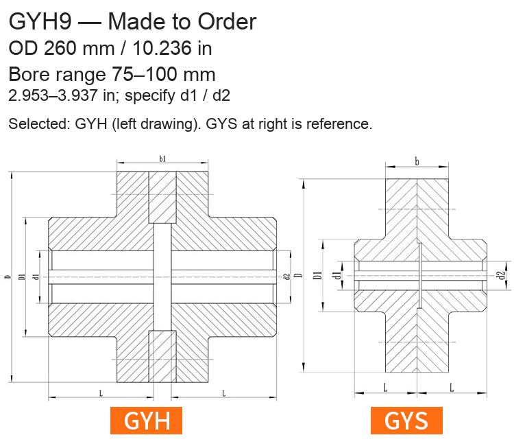
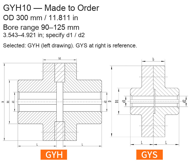
- GYH: clamping-shell type.
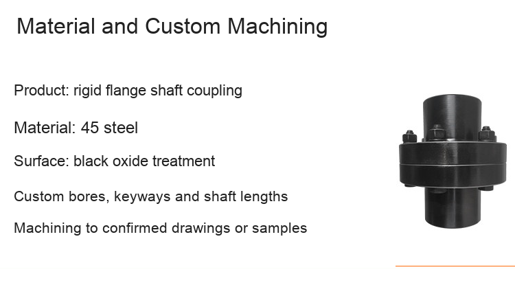
- 45 steel with black oxide surface treatment, as specified in the supplied material information.
Priced Models
Nominal millimetre dimensions are authoritative. Inch equivalents are rounded to three decimal places.
| Model | Outside diameter (mm / in) | Custom bore range (mm / in) |
|---|---|---|
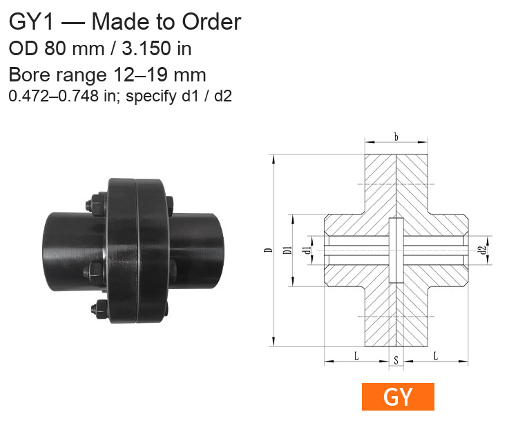
| GY1 | 80 / 3.150 | 12–19 / 0.472–0.748 |
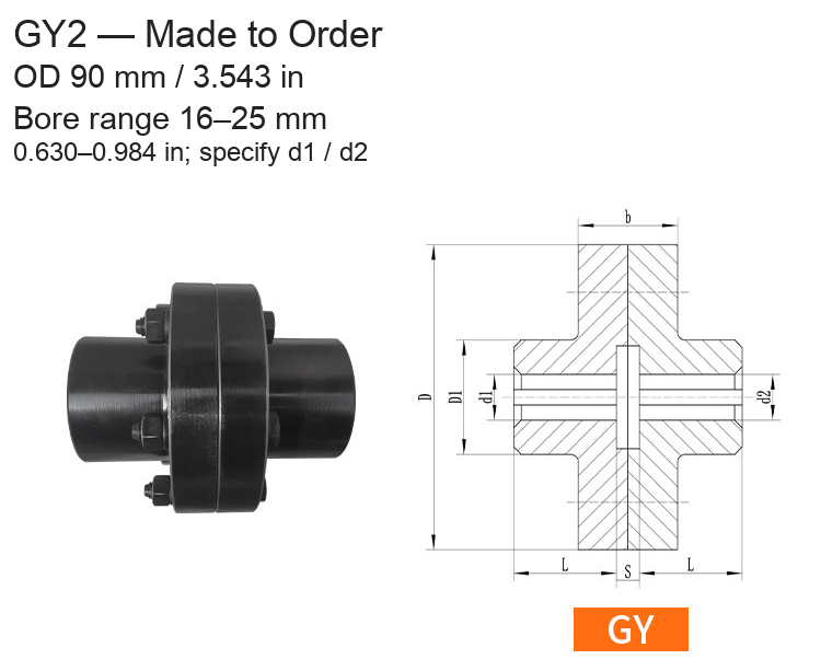
| GY2 | 90 / 3.543 | 16–25 / 0.630–0.984 |
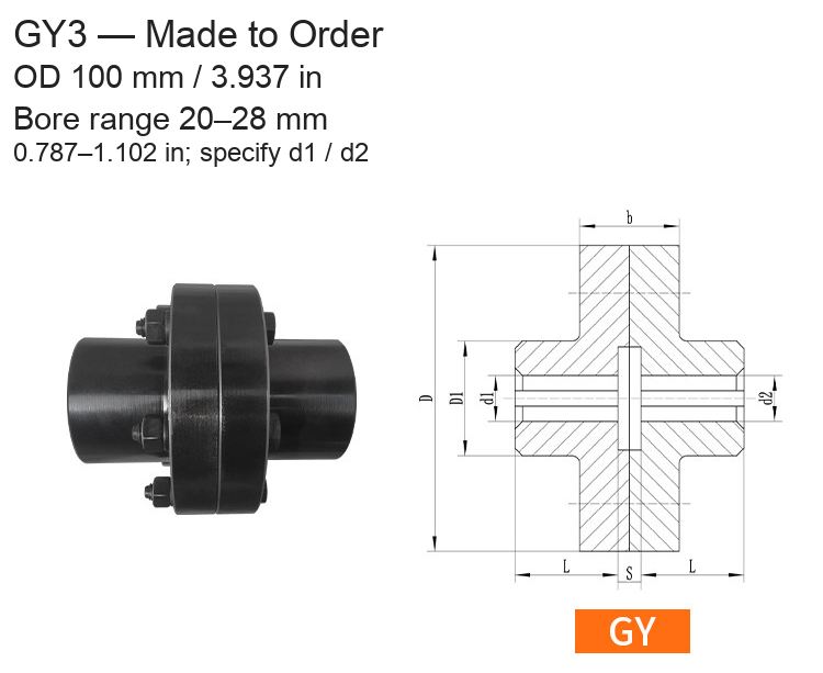
| GY3 | 100 / 3.937 | 20–28 / 0.787–1.102 |
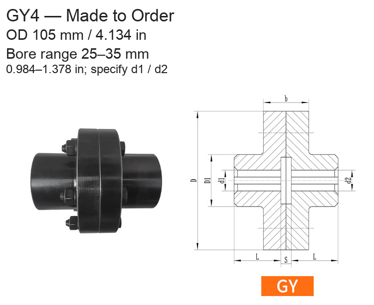
| GY4 | 105 / 4.134 | 25–35 / 0.984–1.378 |
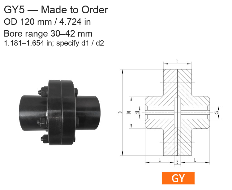
| GY5 | 120 / 4.724 | 30–42 / 1.181–1.654 |
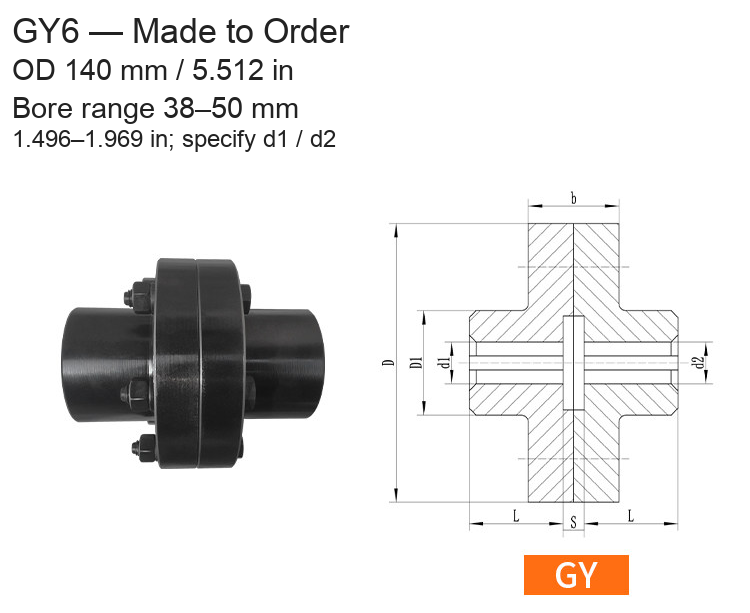
| GY6 | 140 / 5.512 | 38–50 / 1.496–1.969 |
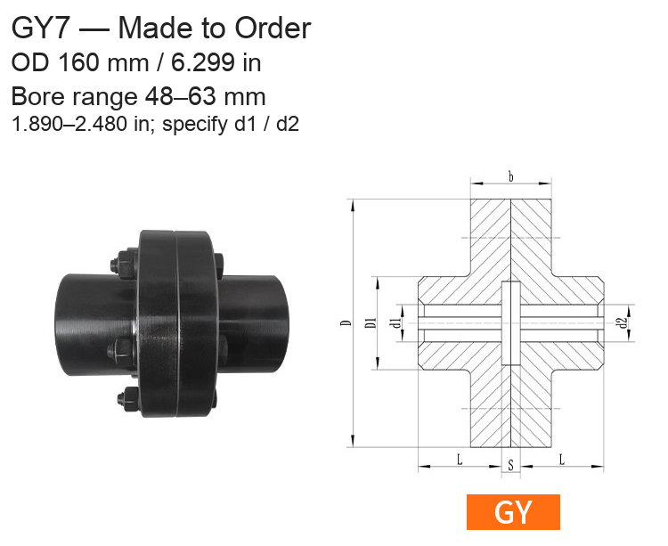
| GY7 | 160 / 6.299 | 48–63 / 1.890–2.480 |
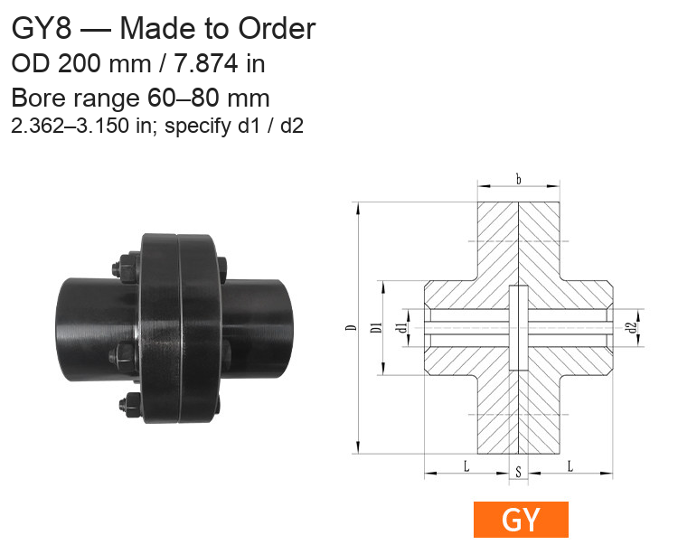
| GY8 | 200 / 7.874 | 60–80 / 2.362–3.150 |
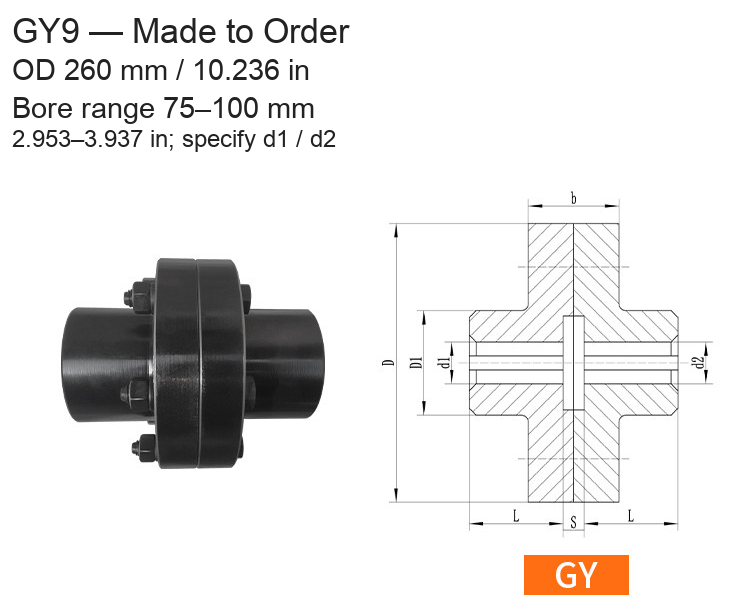
| GY9 | 260 / 10.236 | 75–100 / 2.953–3.937 |
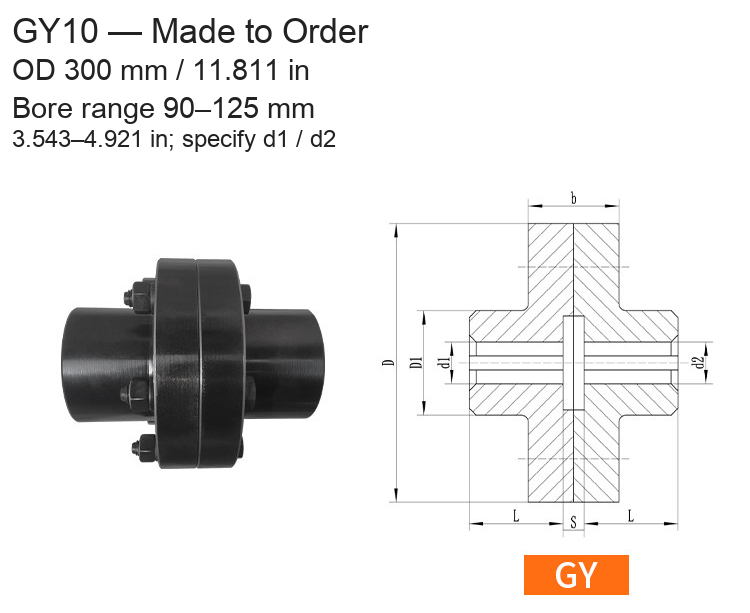
| GY10 | 300 / 11.811 | 90–125 / 3.543–4.921 |
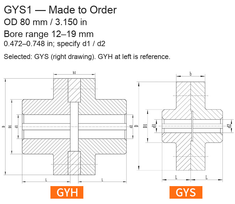
| GYS1 | 80 / 3.150 | 12–19 / 0.472–0.748 |
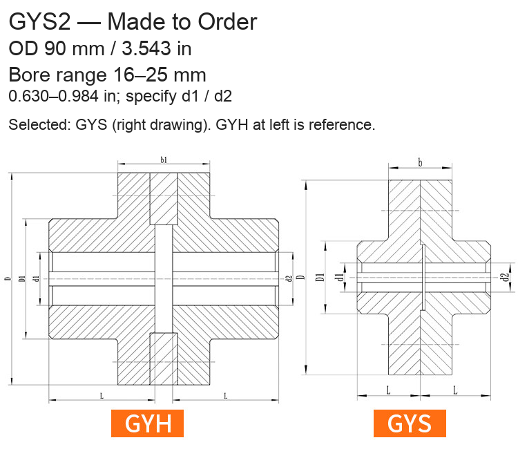
| GYS2 | 90 / 3.543 | 16–25 / 0.630–0.984 |
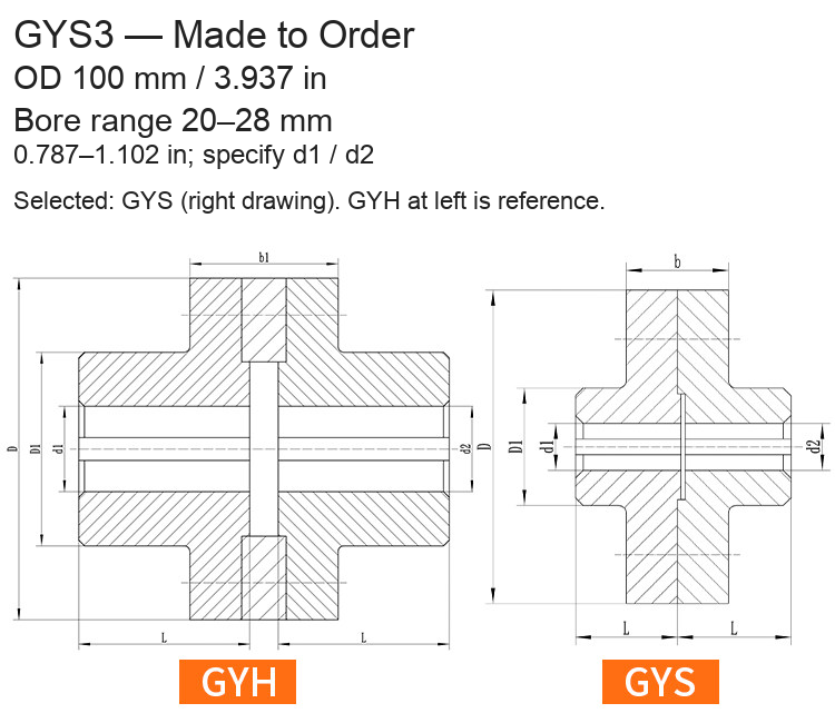
| GYS3 | 100 / 3.937 | 20–28 / 0.787–1.102 |
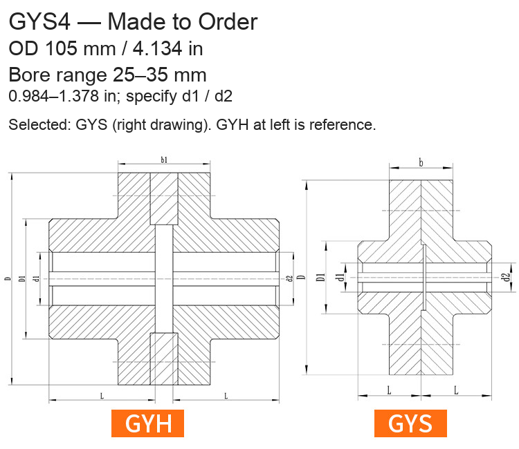
| GYS4 | 105 / 4.134 | 25–35 / 0.984–1.378 |
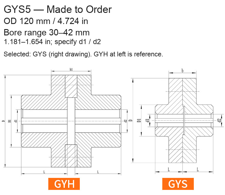
| GYS5 | 120 / 4.724 | 30–42 / 1.181–1.654 |
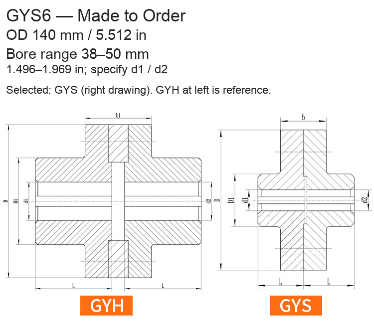
| GYS6 | 140 / 5.512 | 38–50 / 1.496–1.969 |
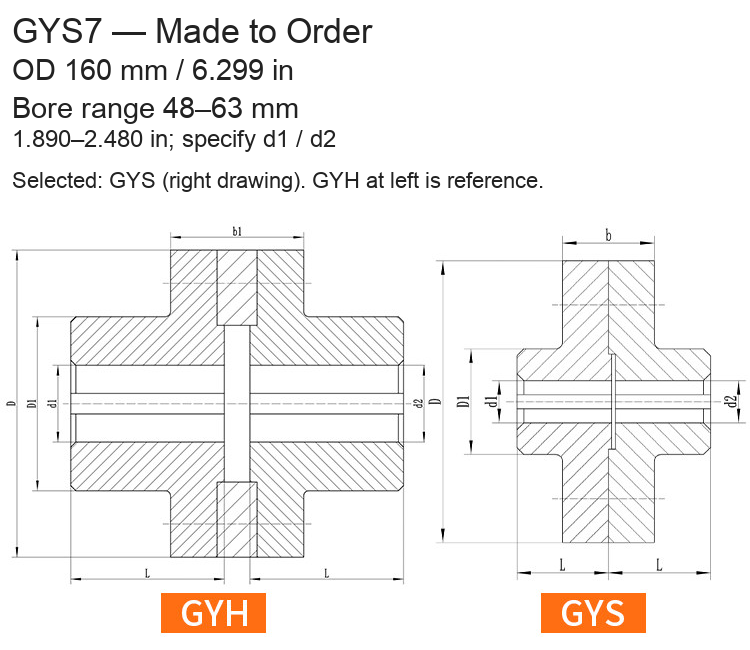
| GYS7 | 160 / 6.299 | 48–63 / 1.890–2.480 |
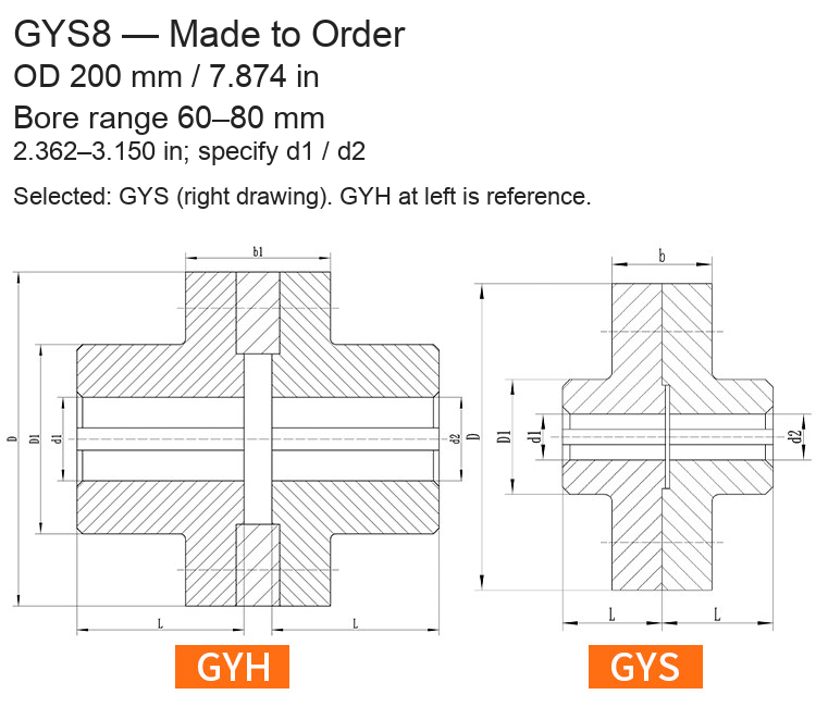
| GYS8 | 200 / 7.874 | 60–80 / 2.362–3.150 |
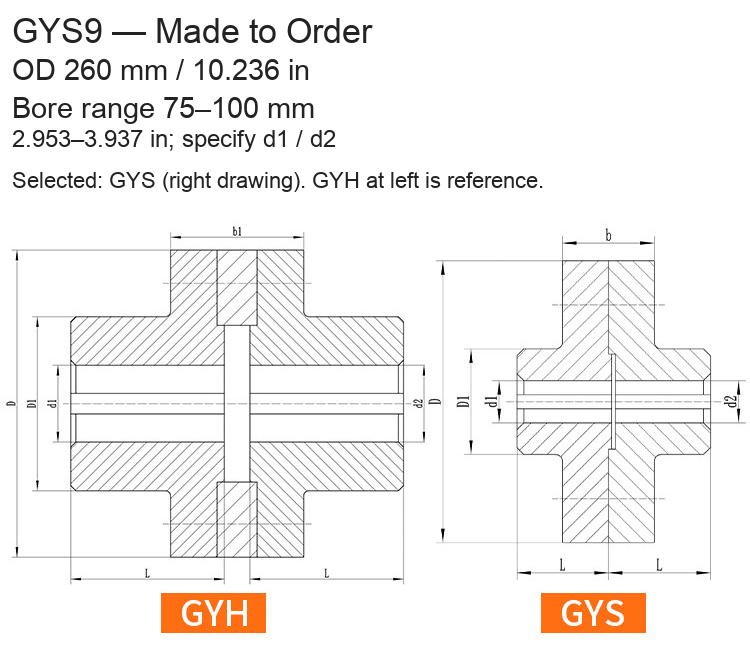
| GYS9 | 260 / 10.236 | 75–100 / 2.953–3.937 |
| GYS10 | 300 / 11.811 | 90–125 / 3.543–4.921 |
| GYH1 | 80 / 3.150 | 12–19 / 0.472–0.748 |
| GYH2 | 90 / 3.543 | 16–25 / 0.630–0.984 |
| GYH3 | 100 / 3.937 | 20–28 / 0.787–1.102 |
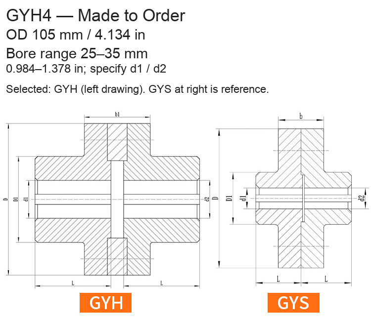
| GYH4 | 105 / 4.134 | 25–35 / 0.984–1.378 |
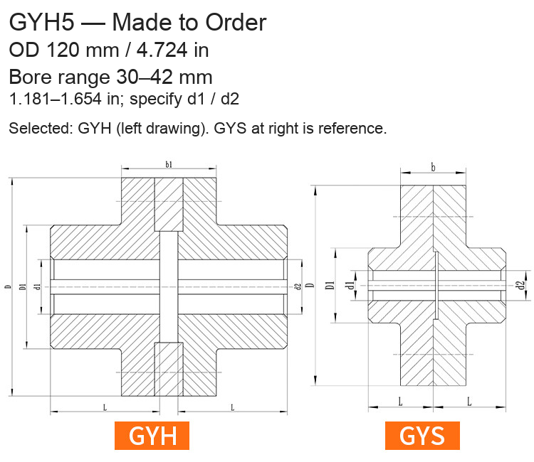
| GYH5 | 120 / 4.724 | 30–42 / 1.181–1.654 |
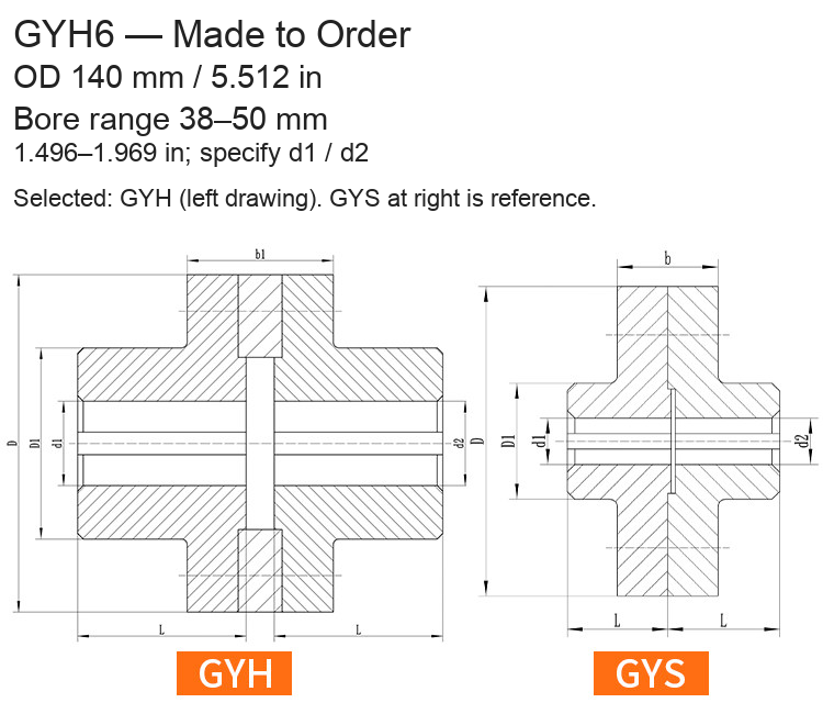
| GYH6 | 140 / 5.512 | 38–50 / 1.496–1.969 |
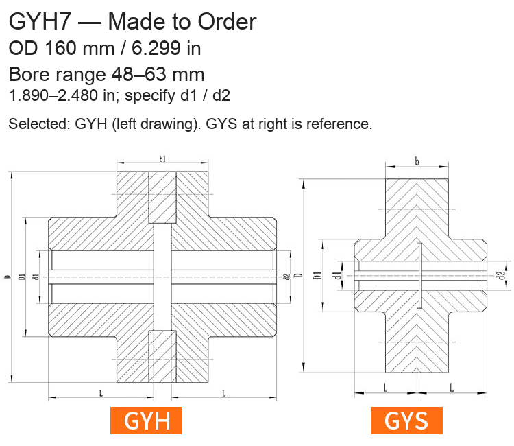
| GYH7 | 160 / 6.299 | 48–63 / 1.890–2.480 |
| GYH8 | 200 / 7.874 | 60–80 / 2.362–3.150 |
| GYH9 | 260 / 10.236 | 75–100 / 2.953–3.937 |
| GYH10 | 300 / 11.811 | 90–125 / 3.543–4.921 |
Drawings and Supplier Reference Table
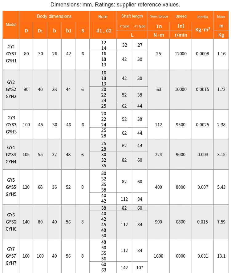
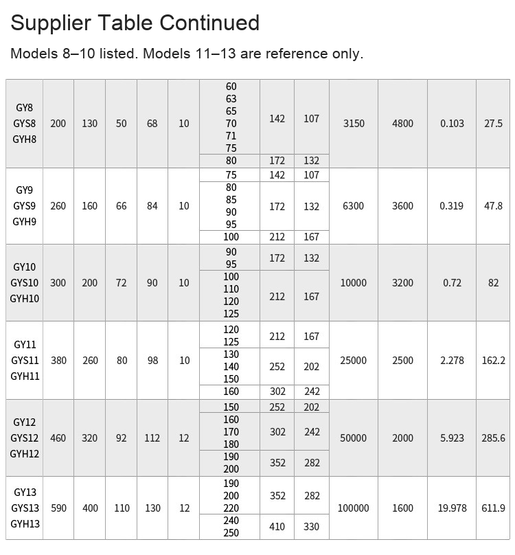
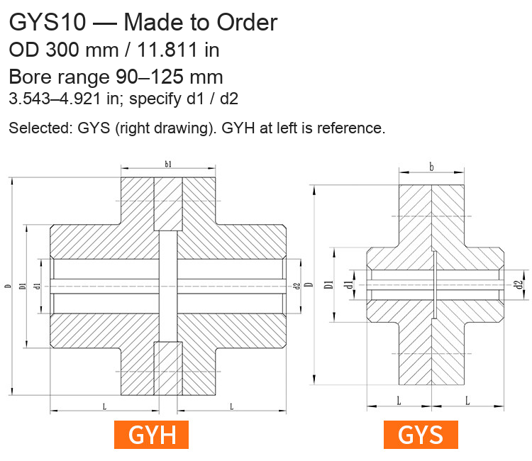
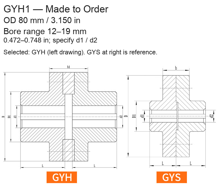
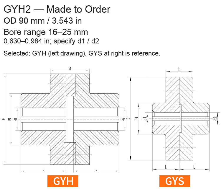
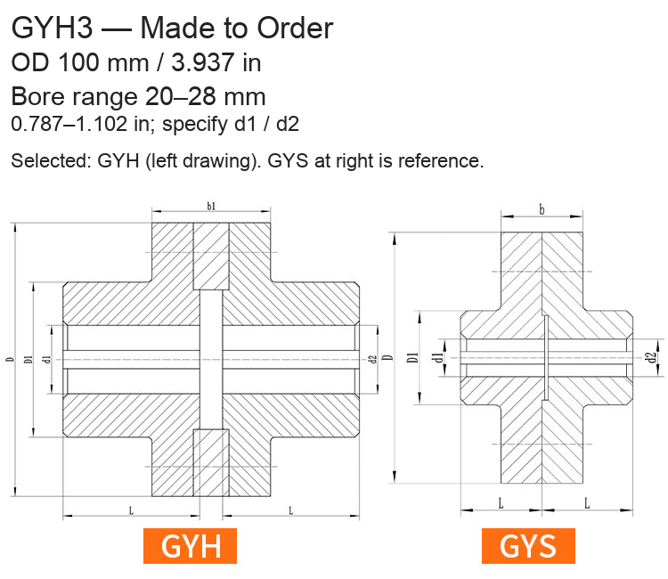
D is the flange outside diameter, D1 the hub diameter, b / b1 the central connection width, S the drawing gap, d1 / d2 the shaft bores and L the shaft engagement length. Y and J1 are the supplier's bore/shaft-end designations. Do not substitute an imperial keyway or thread solely from a rounded inch value. The source table includes nominal torque, permissible speed, rotational inertia and mass; these are supplier reference values, not independent test results or guarantees for a custom-machined configuration. Confirm the actual model and duty requirements before production.
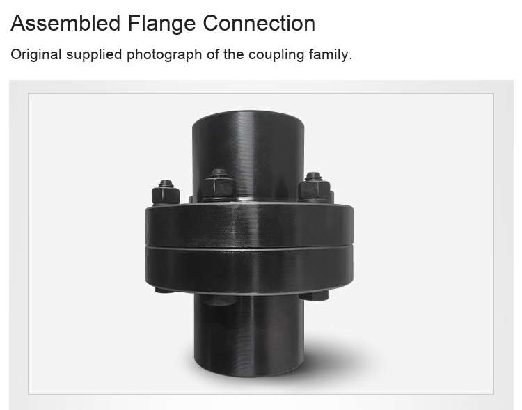
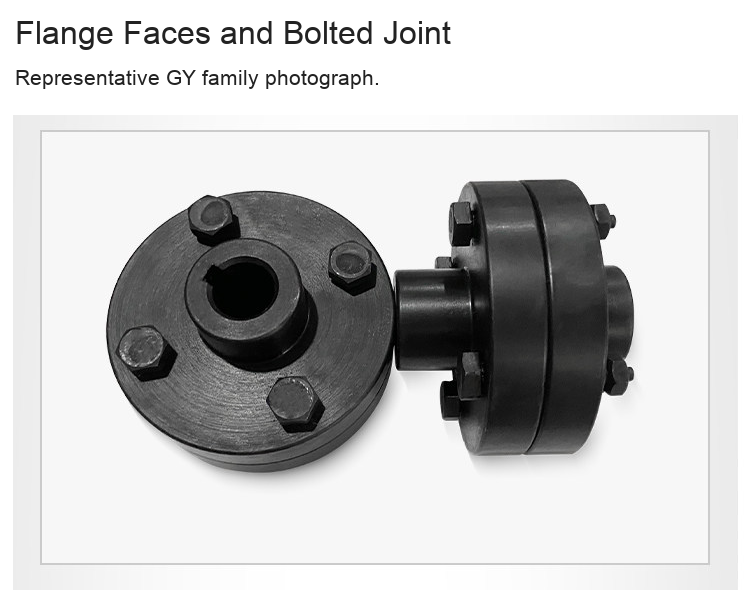
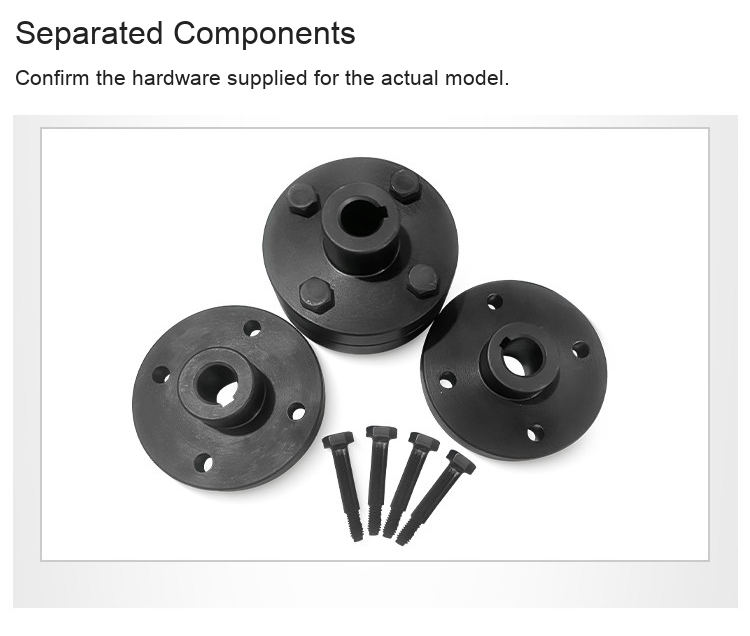
The table also shows series sizes 11–13 for reference. They are not priced selectable options in this product. Overall dimensions and hardware must be checked against the specific drawing. The family photographs show representative assemblies and components, not a separate verified photograph of every machined bore or a pack quantity.
Installation
Rigid flange couplings require accurate shaft alignment. Verify both shafts, the keyways and engagement lengths before assembly. Isolate the equipment, fit the shafts without forcing misalignment, and confirm the correct fastening procedure for the supplied hardware. Shafts and motors shown in application equipment are not included.