GIICL 45-Steel Crowned-Gear Couplings
Made-to-order gear couplings with twelve model sizes. Select GIICL1–GIICL12 and provide the finished dimensions for both shaft connections. The listed bore values are machining ranges, not a fixed supplied bore pair.
Custom Ordering
Provide d1 and d2, bore tolerances, Y/J1 shaft-end requirements where applicable, engagement lengths, keyways, surface finish and the drawing or sample requirements in Order requirements or contact BOLTTE. The manufacturing specification will be confirmed before production. Additional requirements outside the listed model scope must be confirmed before ordering. Custom manufacturing time is confirmed separately from shipping transit estimates.
Construction and Finish
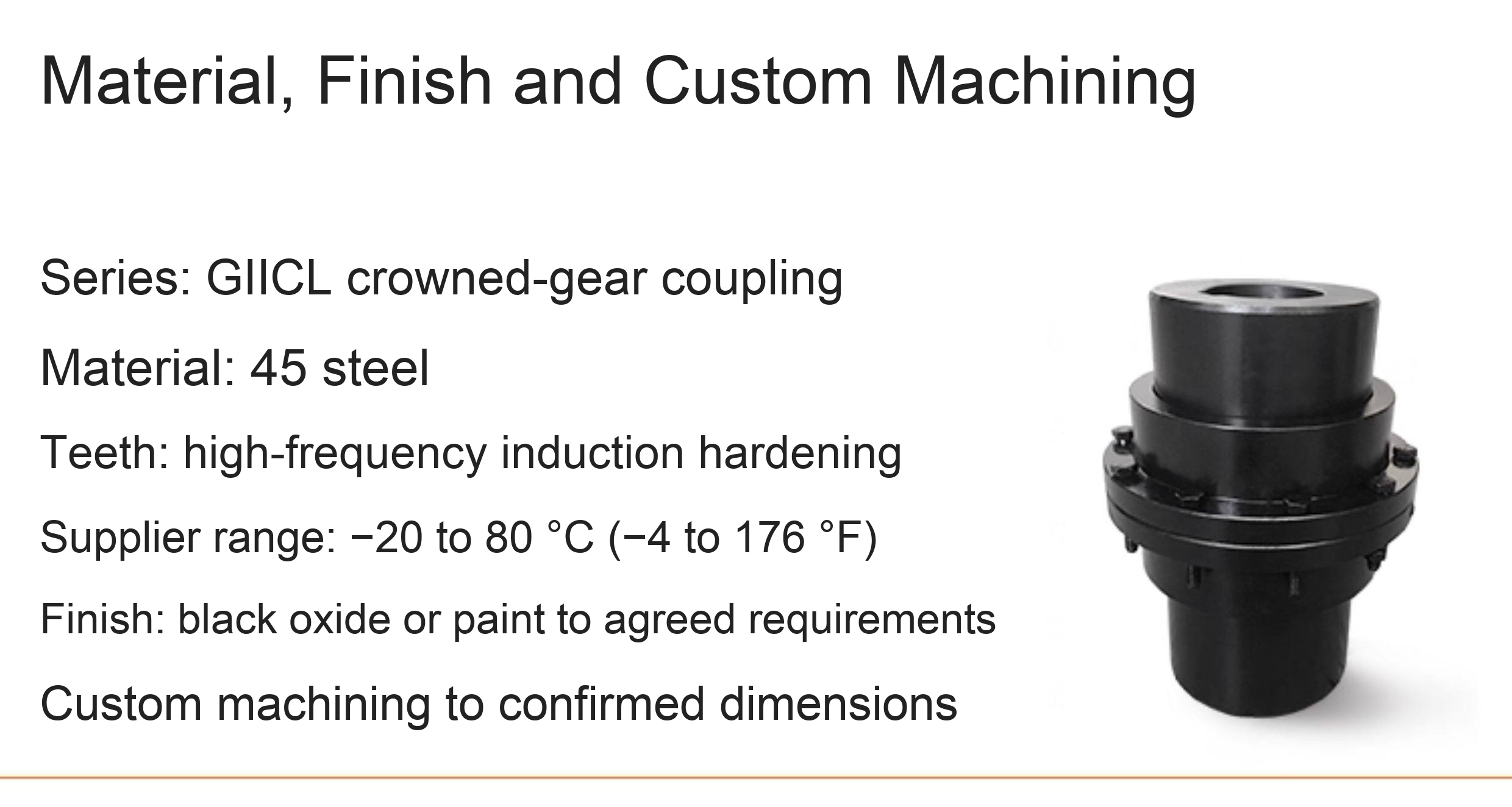
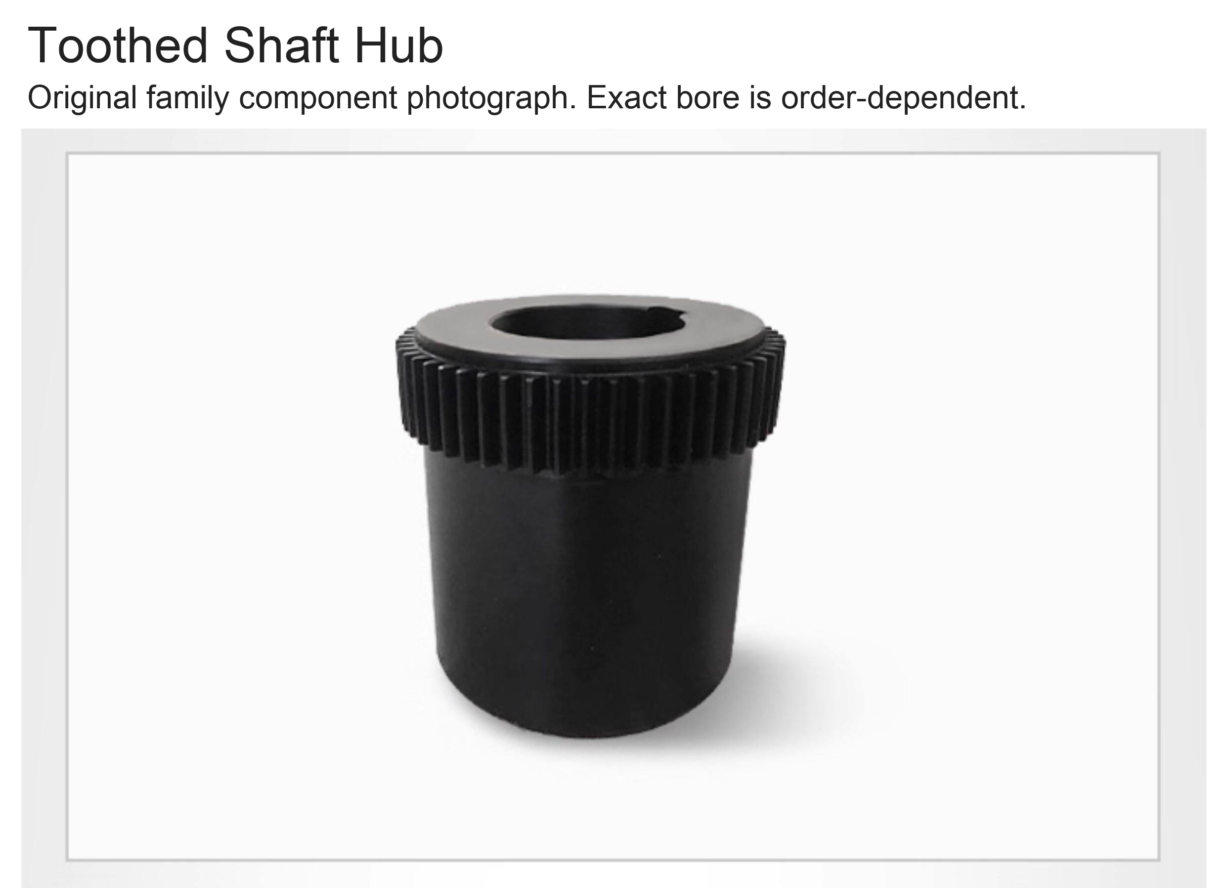
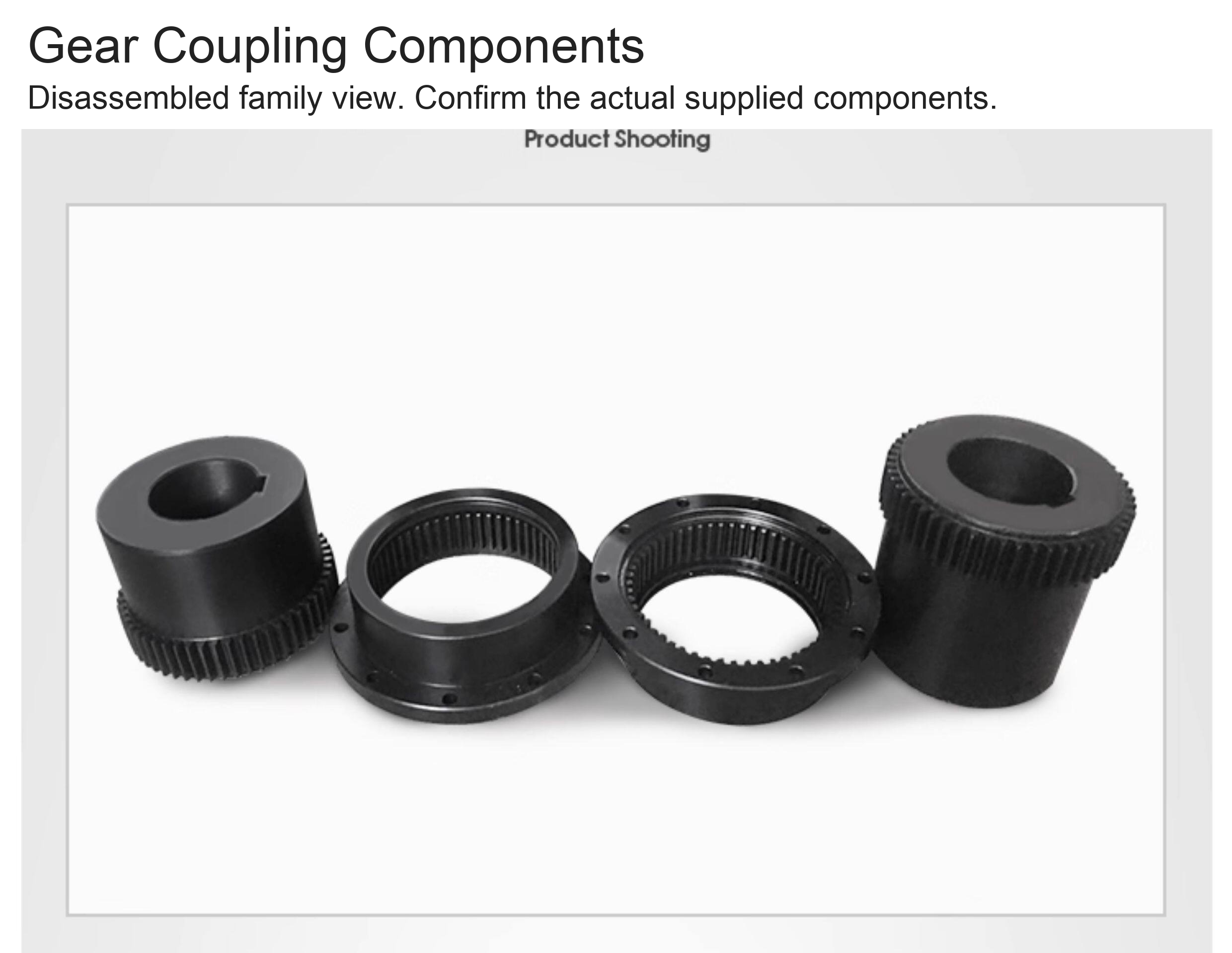
- GIICL crowned-tooth gear-coupling construction with mating external toothed hubs and internal gear sleeves.
- 45 steel, as specified in the supplied material information.
- Supplier-described high-frequency induction hardening of the teeth. No independently certified hardness or heat-treatment record is supplied.
- Black oxide or painted finish according to the confirmed manufacturing requirements.
- Supplier-listed series temperature range −20 to 80 °C (−4 to 176 °F). Confirm suitability for the actual operating duty and supplied assembly.
Priced Model Sizes
Millimetre dimensions remain authoritative. Inch equivalents are rounded to three decimal places.
| Model | Outside diameter (mm / in) | Custom bore range (mm / in) |
|---|---|---|
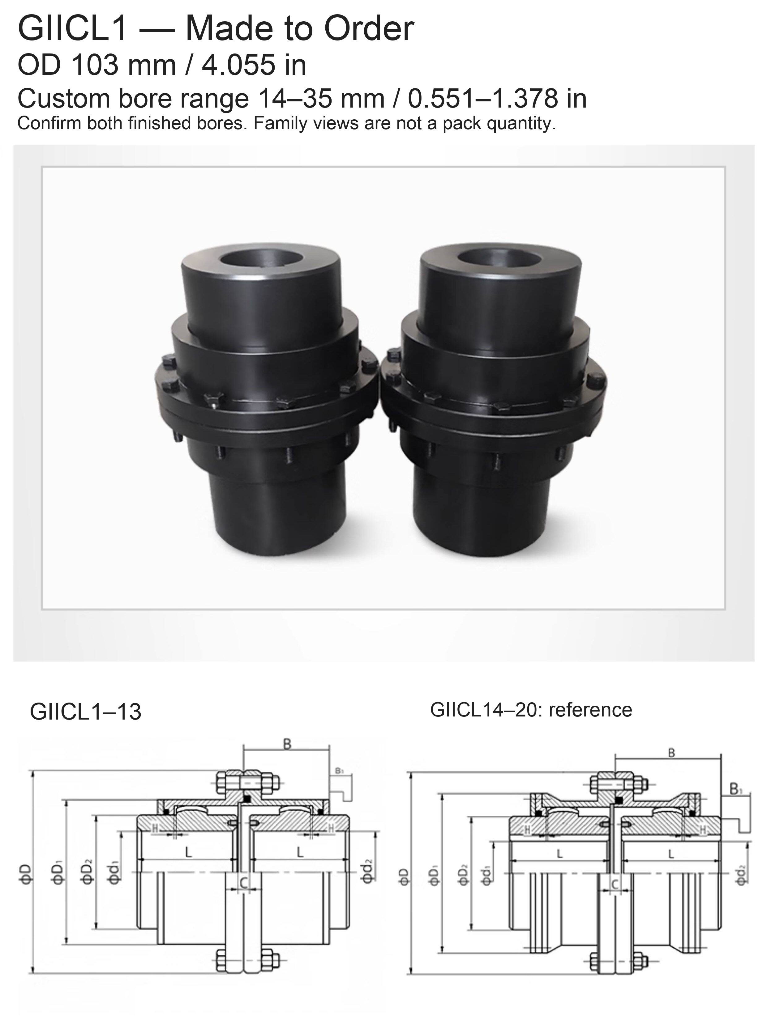
| GIICL1 | 103 / 4.055 | 14–35 / 0.551–1.378 |
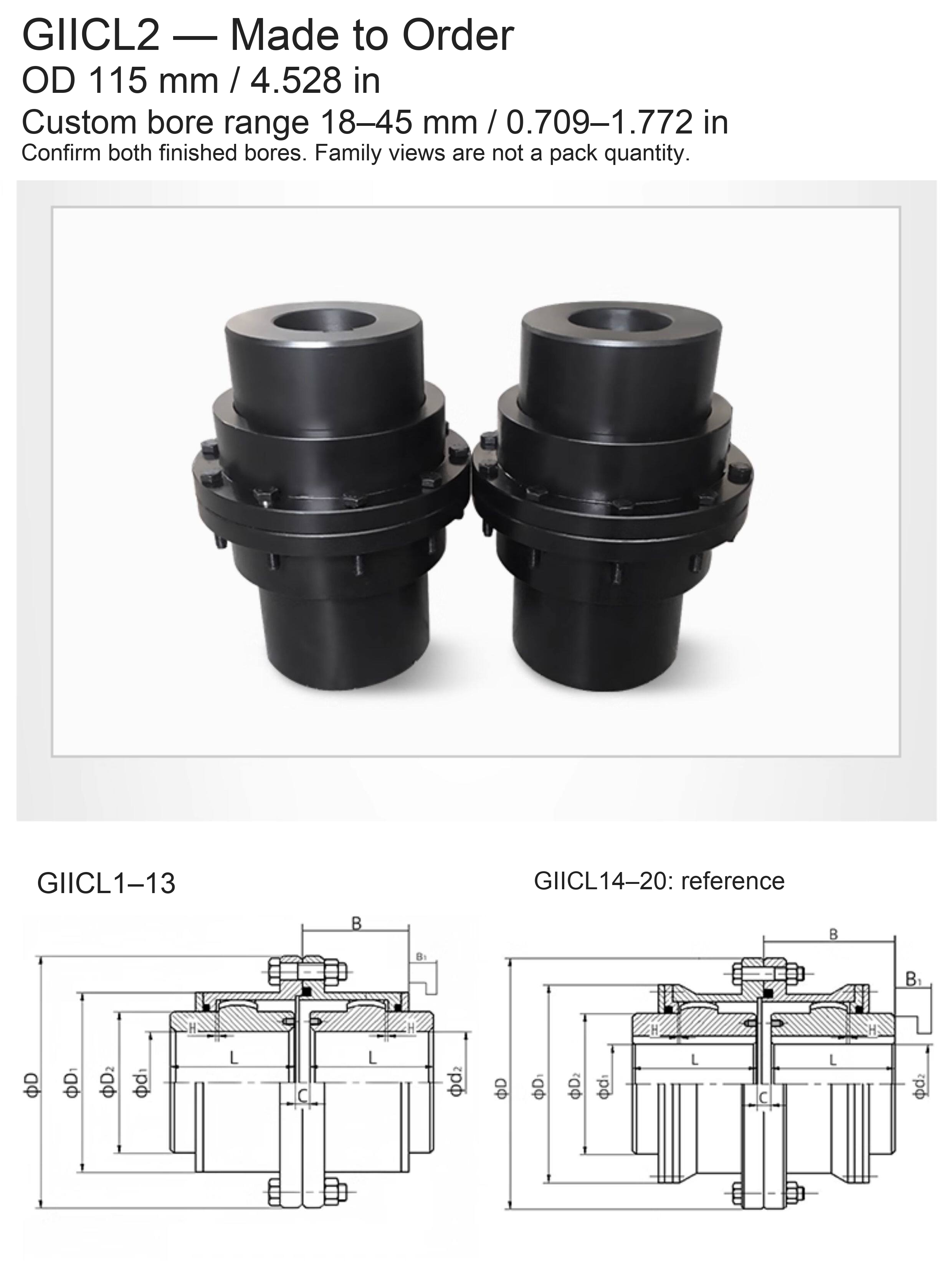
| GIICL2 | 115 / 4.528 | 18–45 / 0.709–1.772 |
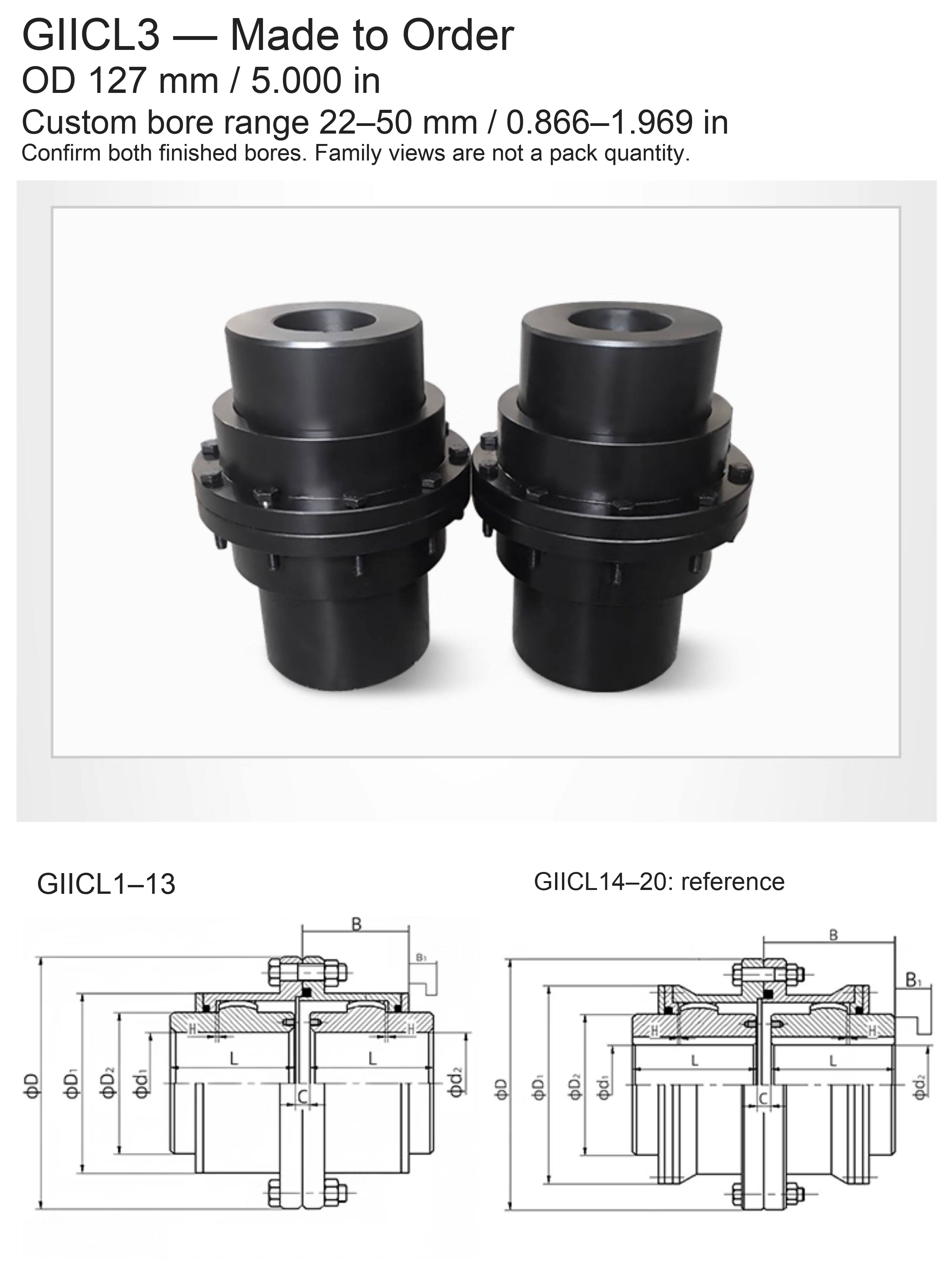
| GIICL3 | 127 / 5.000 | 22–50 / 0.866–1.969 |
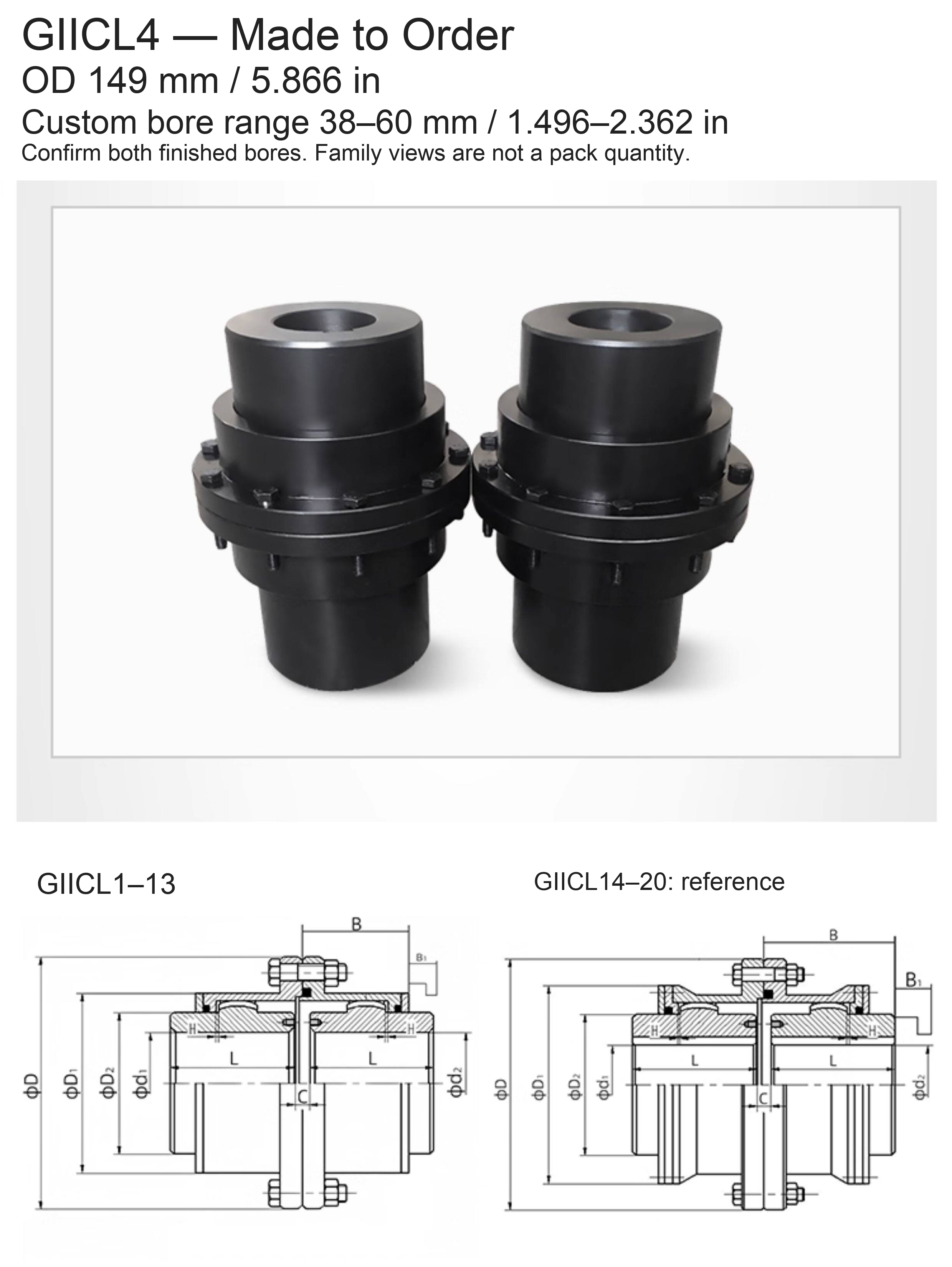
| GIICL4 | 149 / 5.866 | 38–60 / 1.496–2.362 |
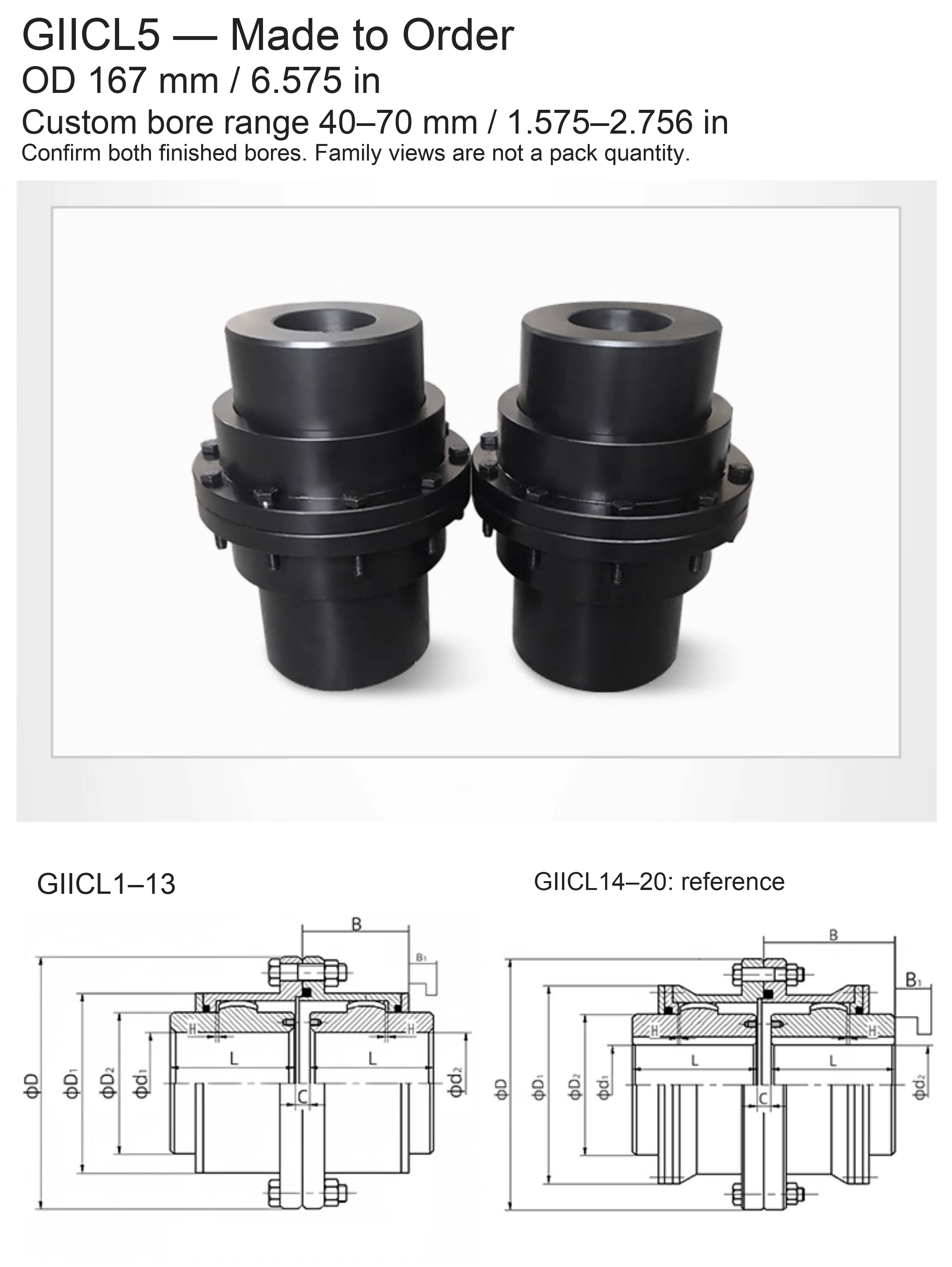
| GIICL5 | 167 / 6.575 | 40–70 / 1.575–2.756 |
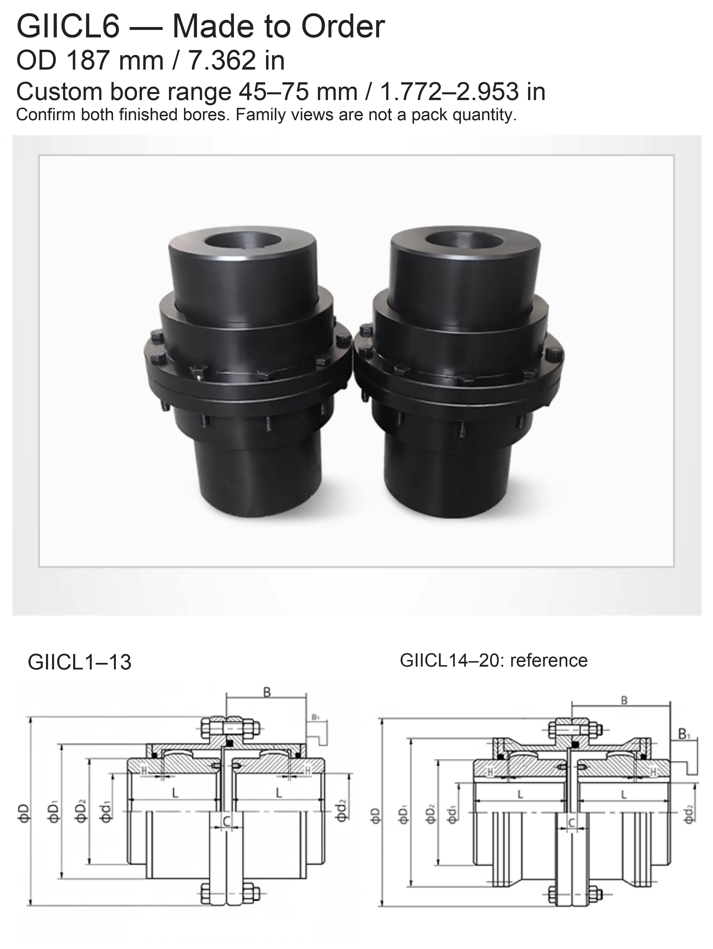
| GIICL6 | 187 / 7.362 | 45–75 / 1.772–2.953 |
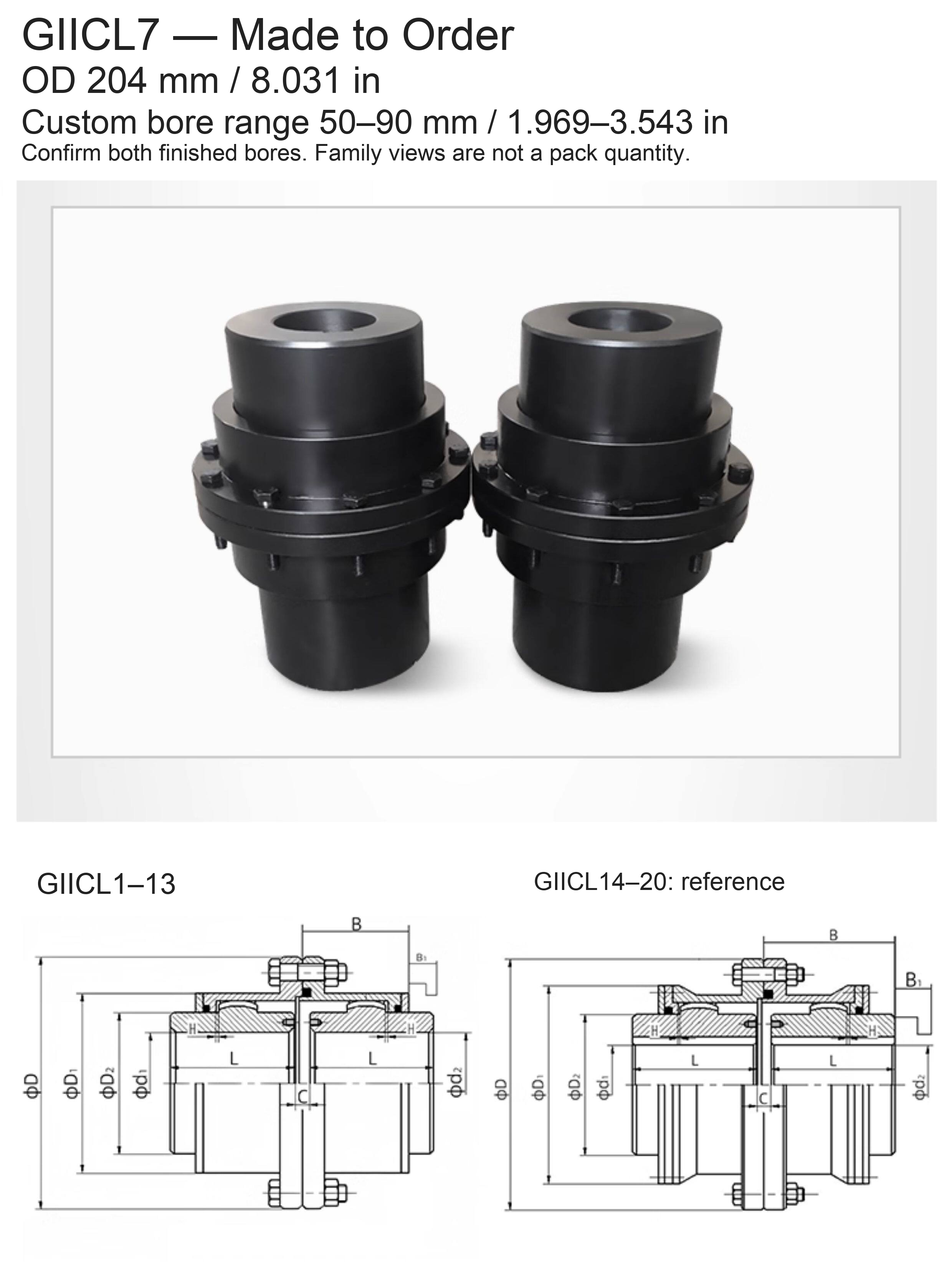
| GIICL7 | 204 / 8.031 | 50–90 / 1.969–3.543 |
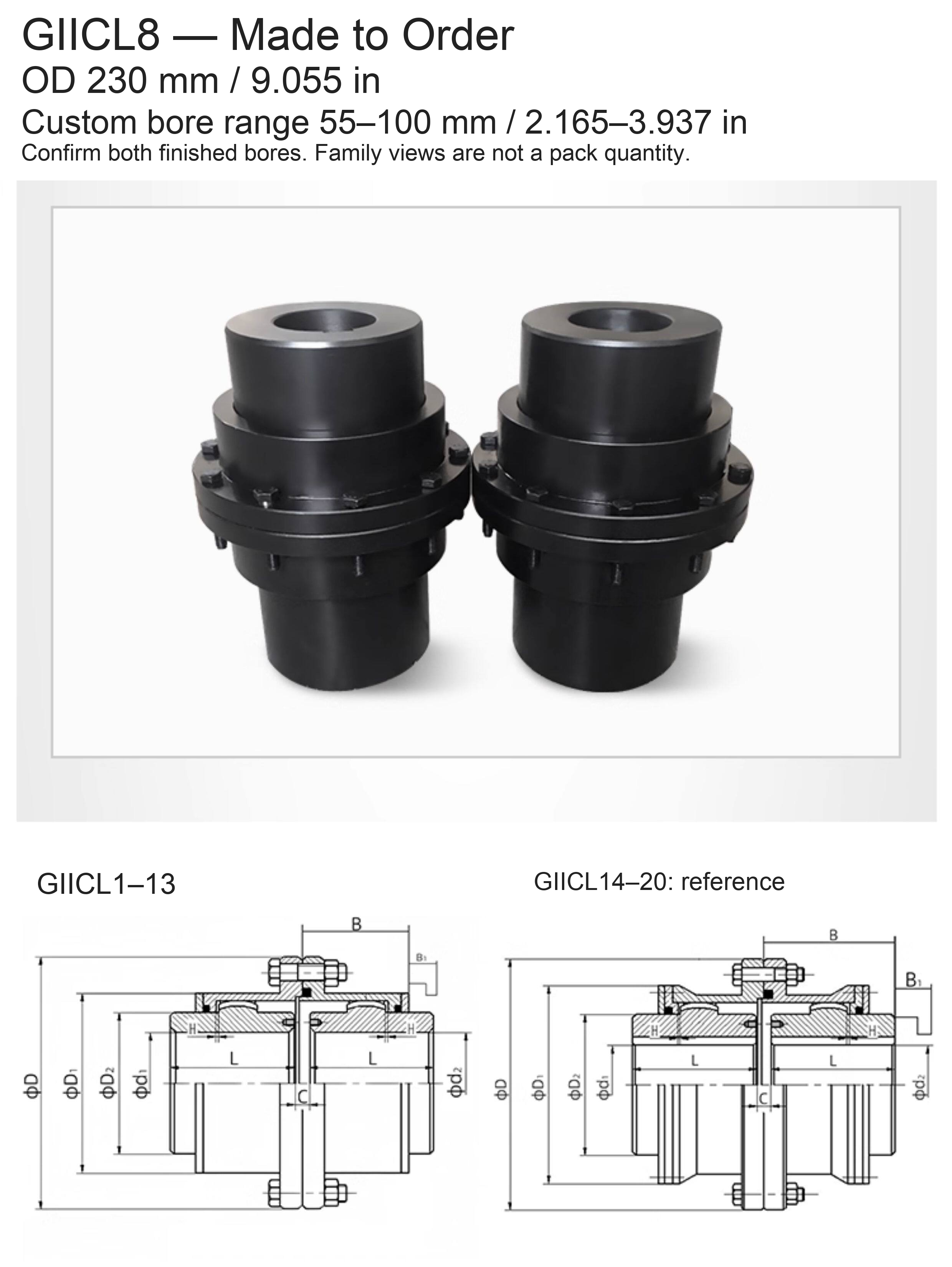
| GIICL8 | 230 / 9.055 | 55–100 / 2.165–3.937 |
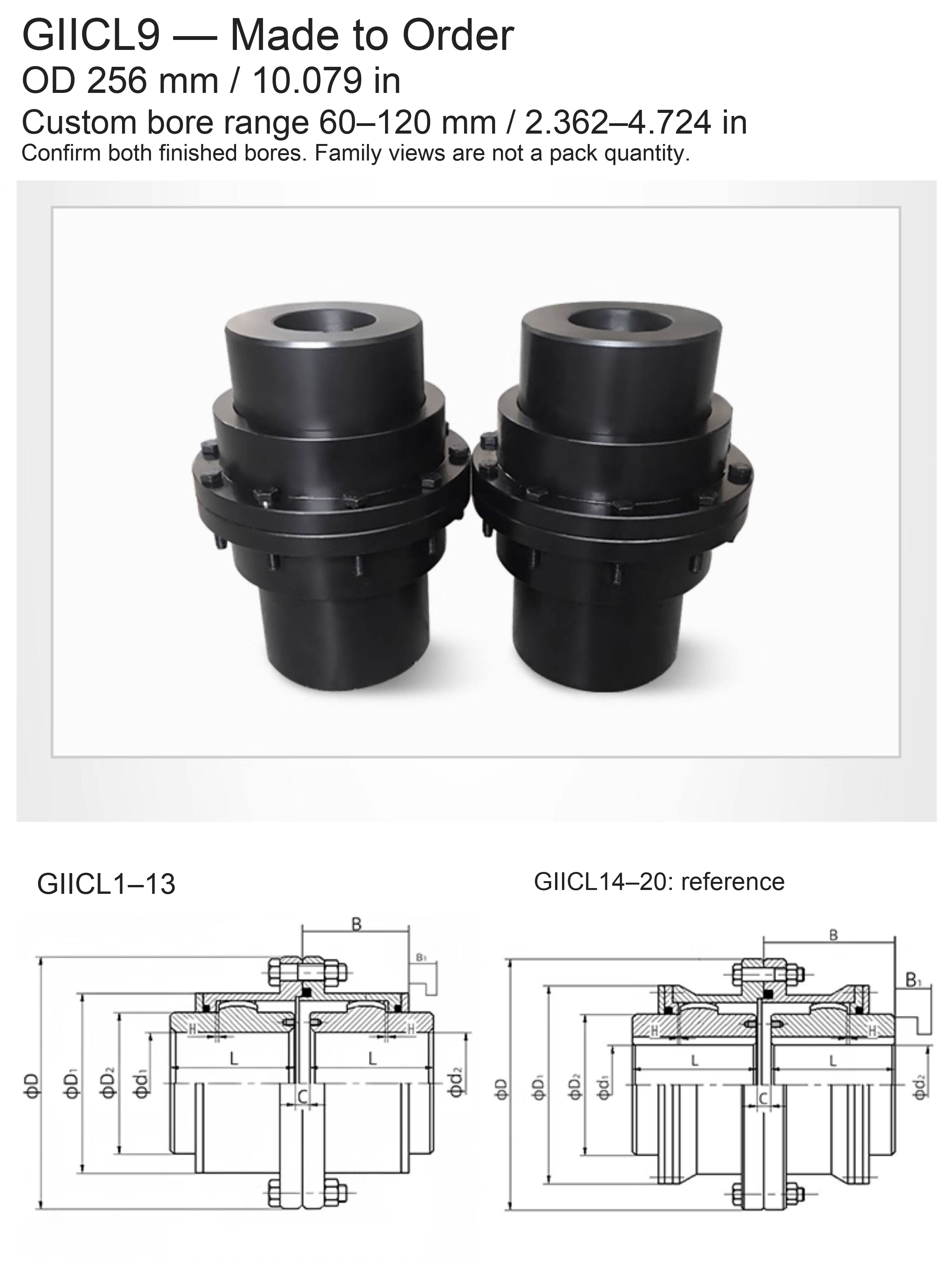
| GIICL9 | 256 / 10.079 | 60–120 / 2.362–4.724 |
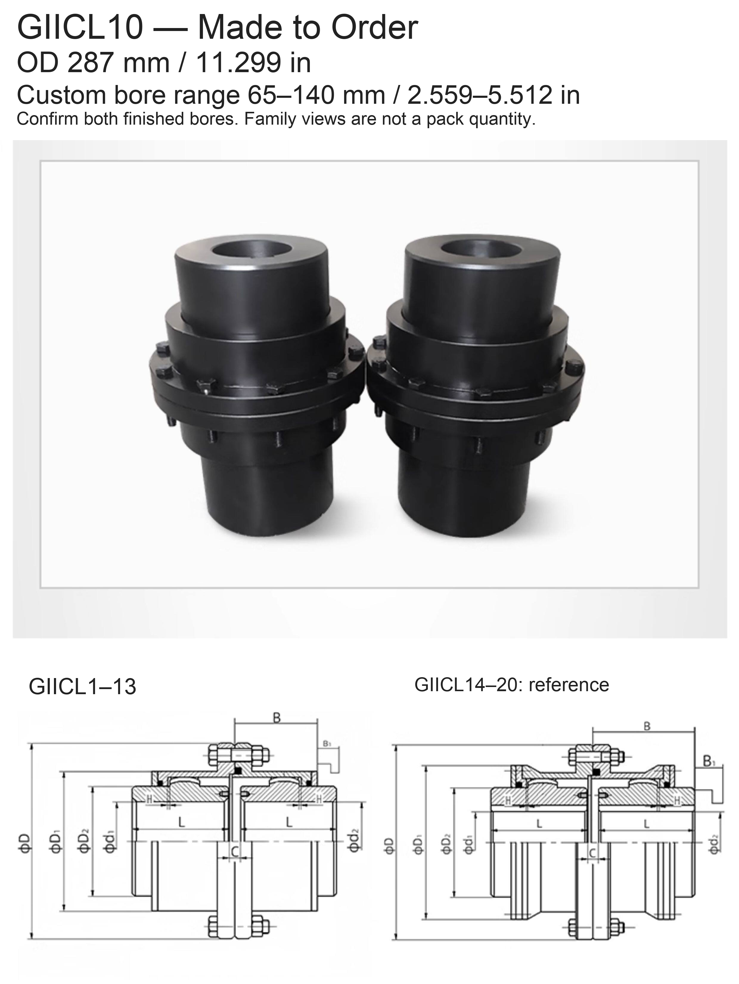
| GIICL10 | 287 / 11.299 | 65–140 / 2.559–5.512 |
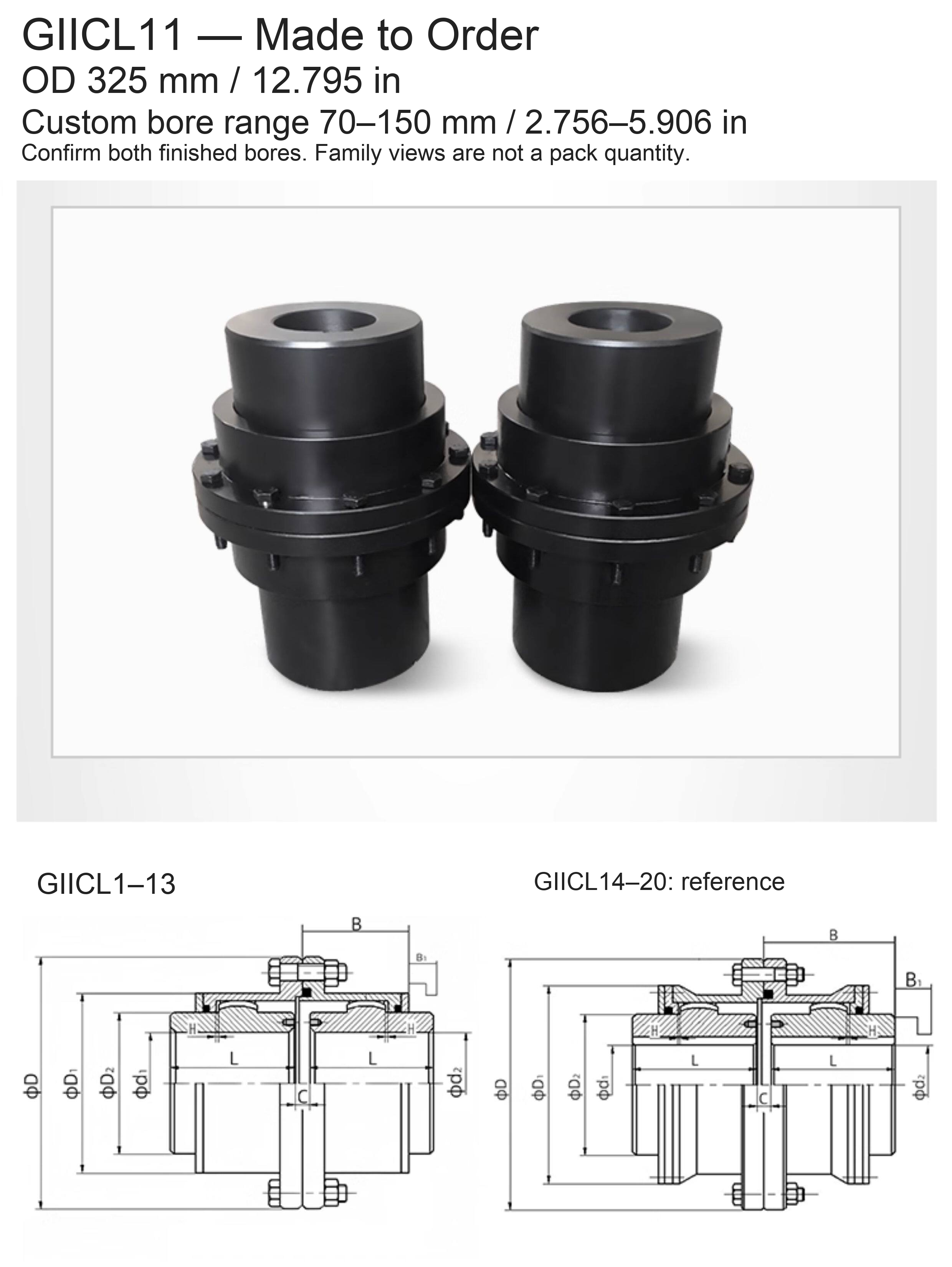
| GIICL11 | 325 / 12.795 | 70–150 / 2.756–5.906 |
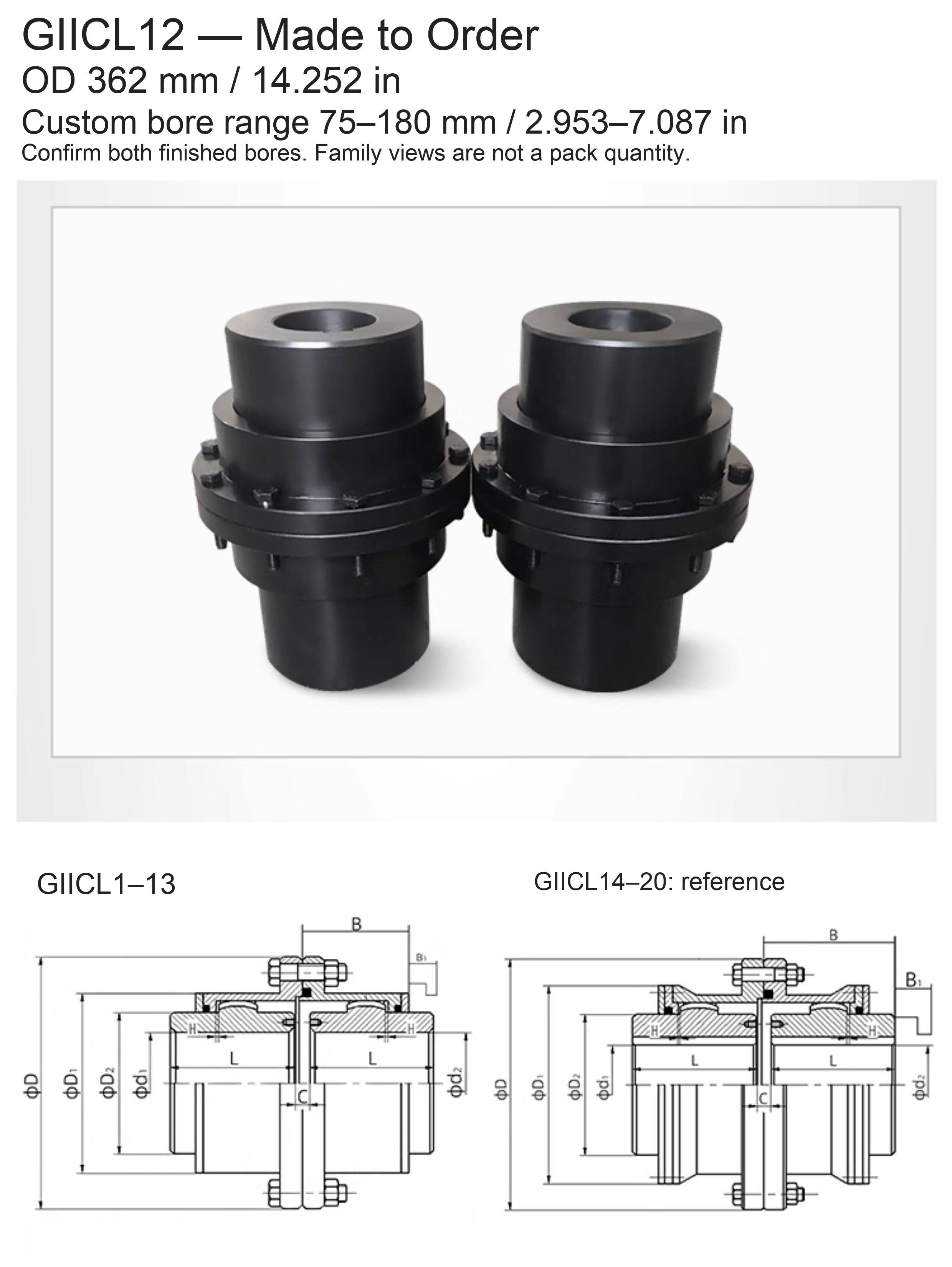
| GIICL12 | 362 / 14.252 | 75–180 / 2.953–7.087 |
Original Drawings and Reference Tables
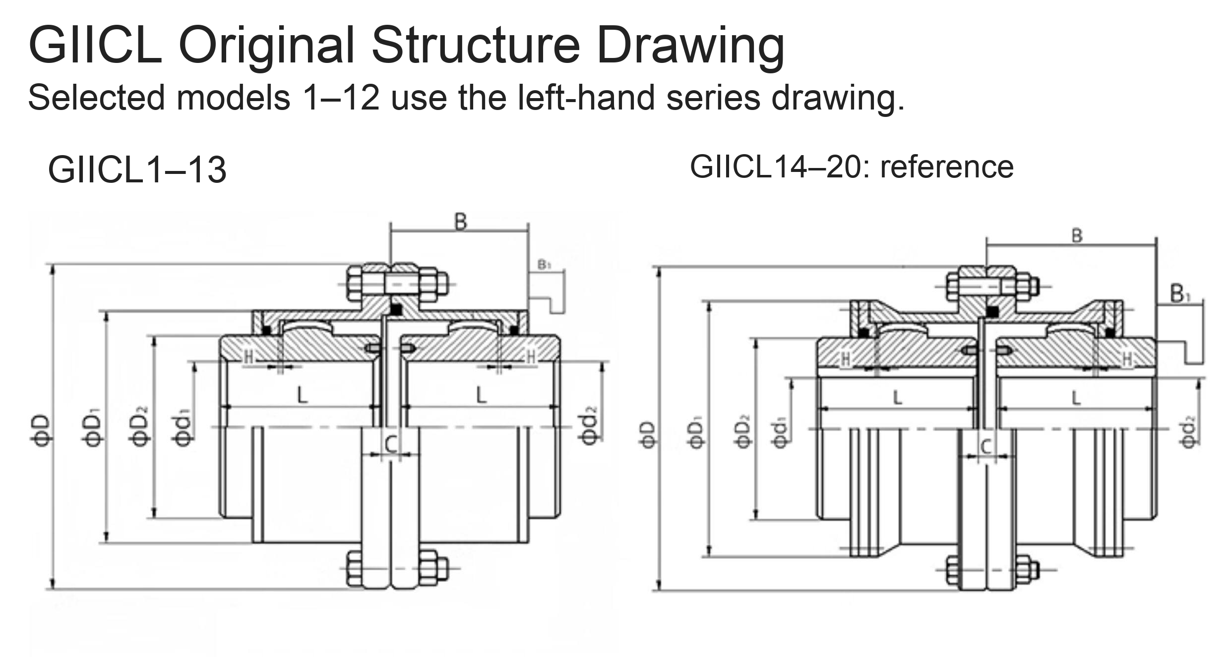
The left-hand original drawing applies to GIICL1–GIICL13 and covers the twelve priced models. The right-hand GIICL14–GIICL20 drawing is reference only. D is the outside diameter; D1 and D2 are the other indicated body diameters; d1 and d2 are the finished shaft bores; L is the shaft engagement length; B/B1, H and C retain their original drawing meanings. Confirm the specific drawing and fits before machining.
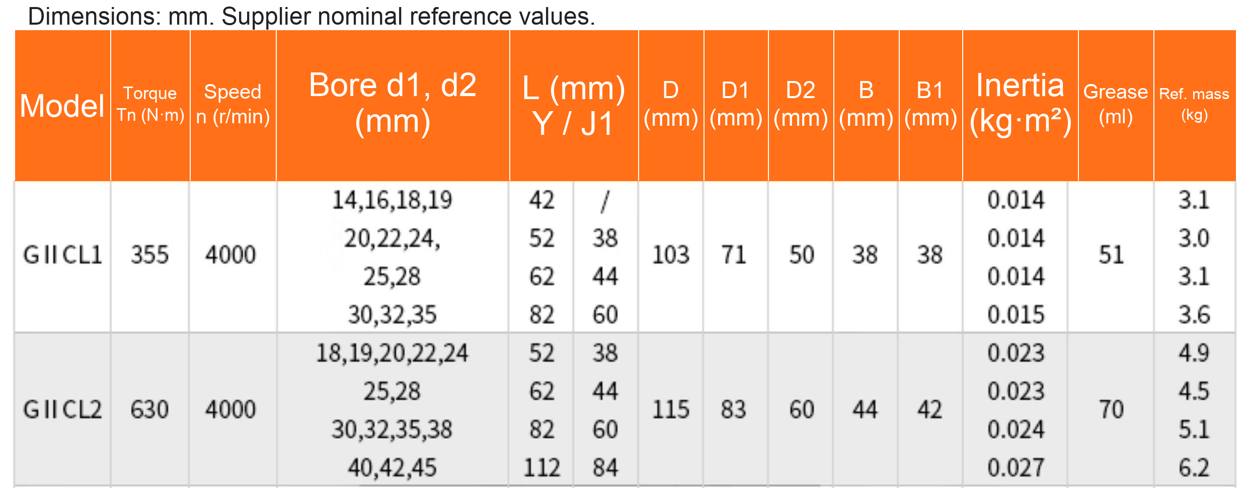
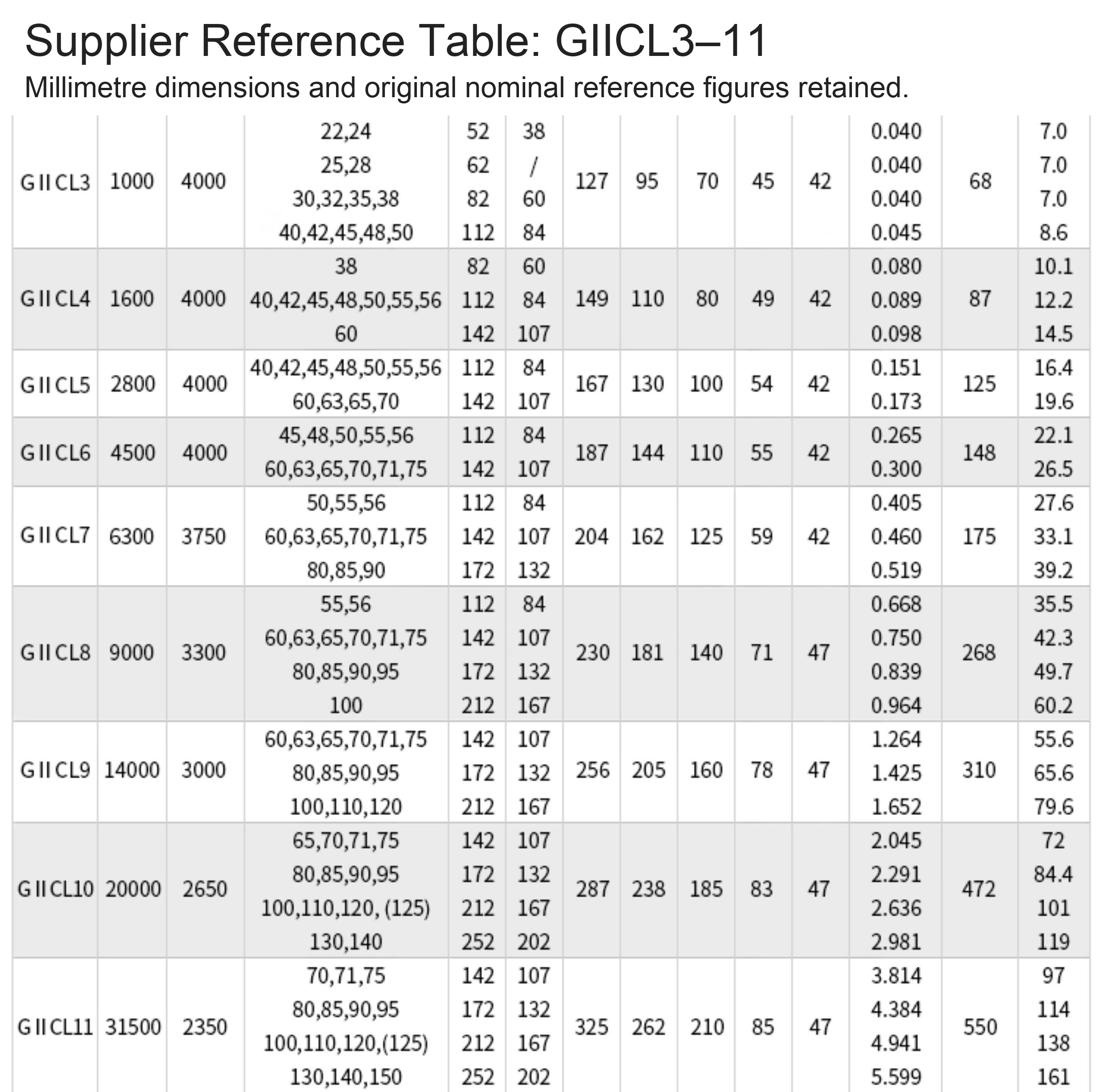
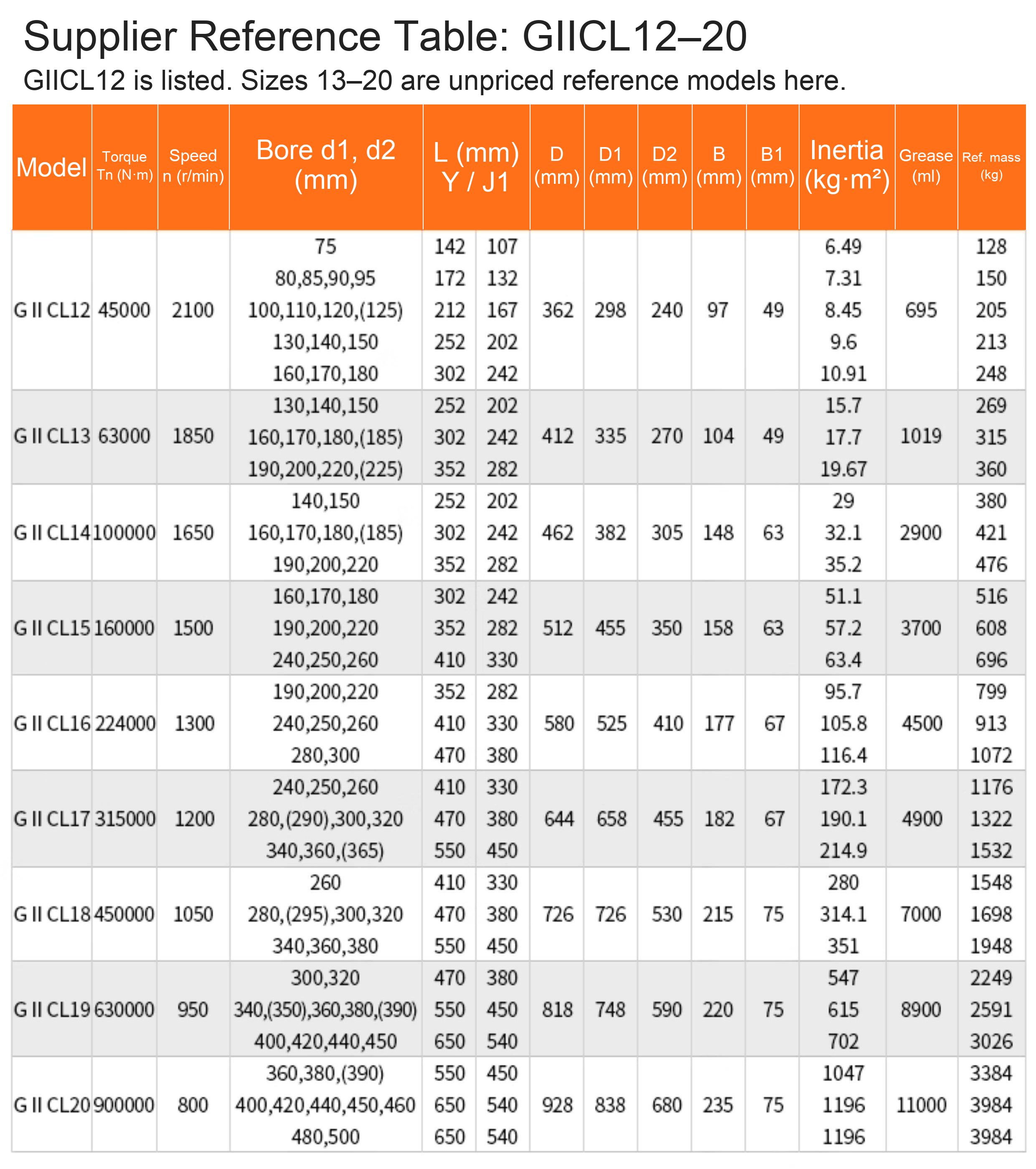
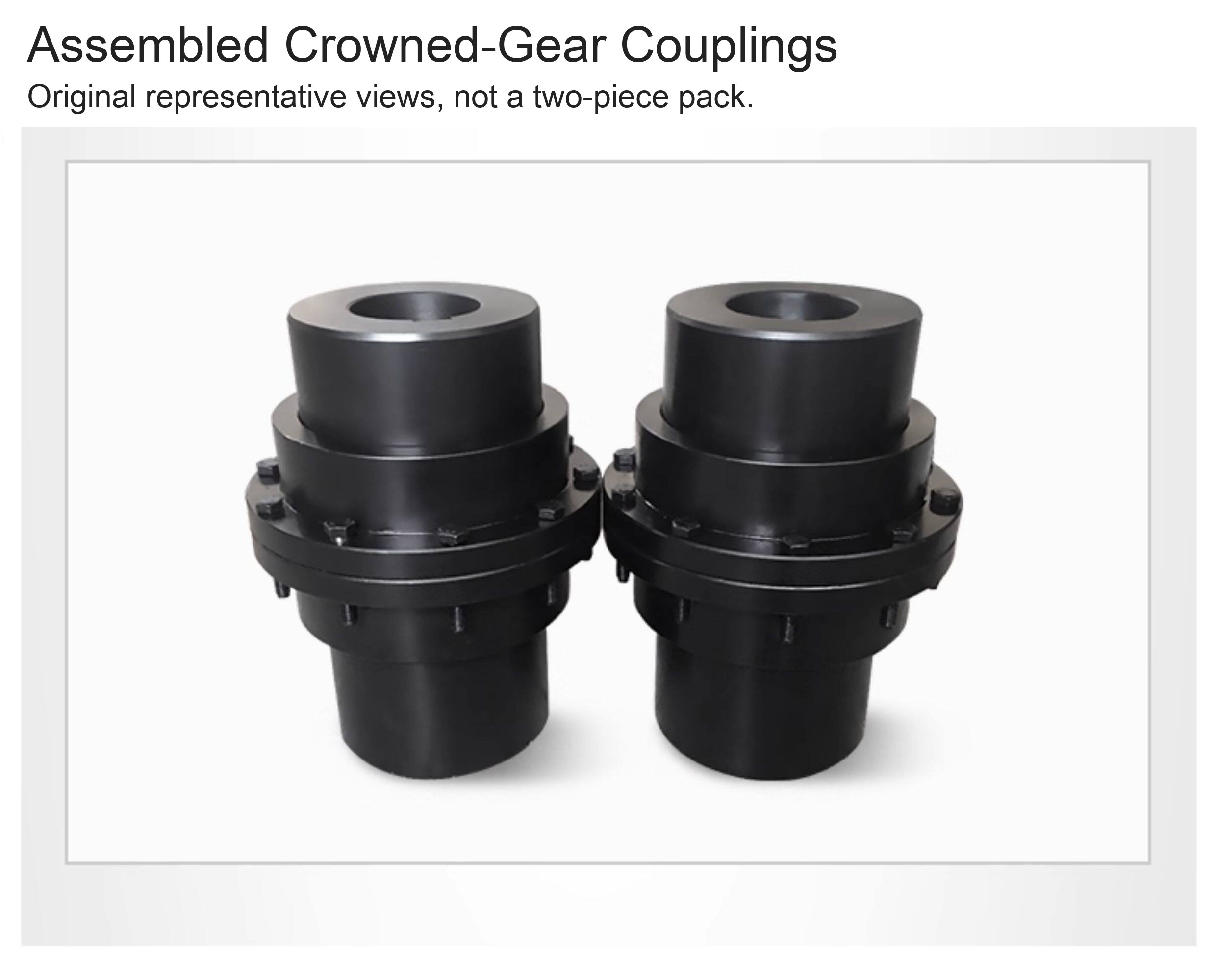
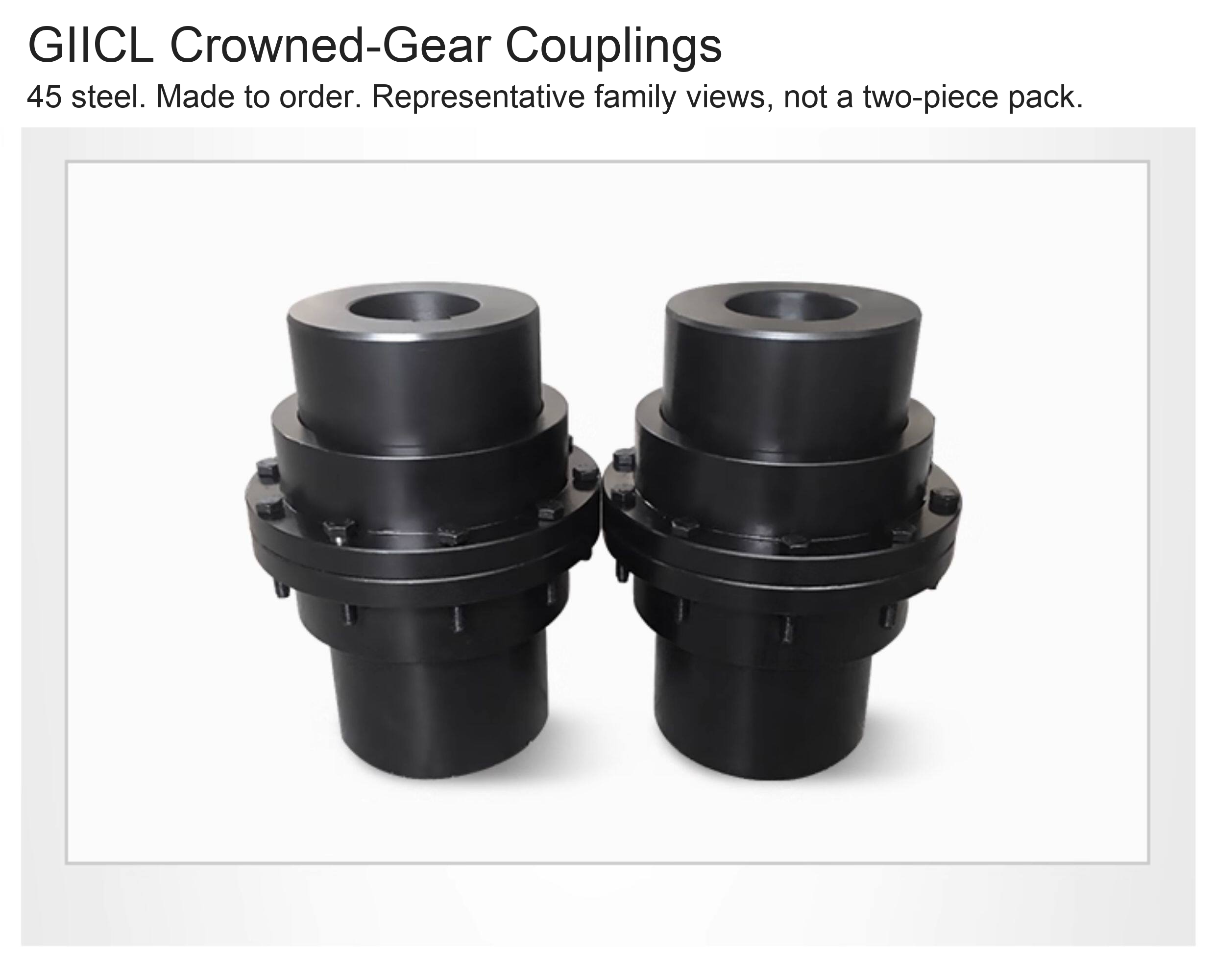
The original supplier tables include nominal torque, permissible speed, bore and engagement-length options, body dimensions, rotational inertia, grease volume and reference mass. These are supplier reference data, not independent test certificates and must be checked for the actual custom-machined configuration. GIICL13–GIICL20 appear for reference but have no selectable prices here. Model images and inch-labelled options describe the quoted machining ranges; the photographs are representative series views and do not establish a two-piece package or separately verified appearance of every bore.
Selection, Installation and Lubrication
The source identifies fan, motor, pump and industrial machinery applications. Confirm the required torque, speed, shaft interfaces, alignment and space against the actual coupling drawing. Isolate equipment before assembly, verify both shaft fits and keyways, and follow the fastening and lubrication requirements for the supplied assembly. Grease volumes in the source table are reference values; grease specification, fill procedure and maintenance interval must be confirmed for the actual duty. No numerical misalignment allowance, universal equipment compatibility or a fixed service life is asserted. Shafts and motors are not included.