





AC Aluminum Ring Air Wipers
An AC ring air wiper directs a circumferential stream of compressed air around a workpiece passing through its center. Use it for surface blow-off, water removal and drying on suitably sized wire, cable, tube or rod. The split body can be opened for fitting around an existing line after the supply is isolated. This product needs an external compressed-air supply.
Available Models
| Model | Bore reference | Original USD | Sale USD |
|---|---|---|---|
| AC10 | Confirm selected size | 680 | 544.00 |
| AC13 | 13 mm (0.512 in) | 780 | 624.00 |
| AC25 | 25 mm (0.984 in) | 850 | 680.00 |
| AC32 | Confirm selected size | 930 | 744.00 |
| AC38 | 38 mm (1.496 in) | 950 | 760.00 |
| AC40 | 40 mm (1.575 in) | 1050 | 840.00 |
| AC51 | 51 mm (2.008 in) | 1260 | 1008.00 |
| AC64 | 64 mm (2.520 in) | 1350 | 1080.00 |
| AC76 | 76 mm (2.992 in) | 1450 | 1160.00 |
| AC89 | 89 mm (3.504 in) | 1560 | 1248.00 |
| AC102 | 102 mm (4.016 in) | 1650 | 1320.00 |
| AC127 | 127 mm (5.000 in) | 1750 | 1400.00 |
| AC152 | 152 mm (5.984 in) | 1850 | 1480.00 |
One selected ring air wiper is supplied per unit. All selectable options in this source group are described as aluminum alloy. Stainless equivalents in the reference table are not selectable stainless products here. The source does not independently list dimensions for AC10 or AC32; these named, priced models remain available subject to a dimension check, with no bore or outside size inferred from the model number. Shared photographs illustrate the family rather than each selected size.
What the Air Wiper Does
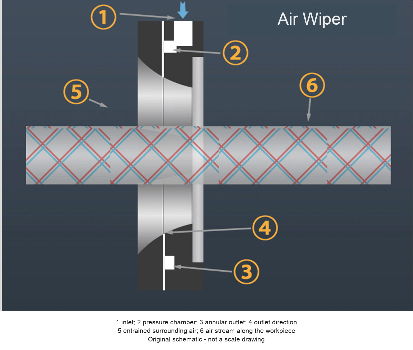
Compressed air enters the pressure chamber and leaves through an annular outlet toward one side of the ring. The source schematic shows surrounding air entrained into the outgoing stream. A centered workpiece can pass through the ring while the airflow moves surface droplets or loose debris away. Results depend on workpiece shape, clearance, line speed, pressure, air delivery and the amount of liquid or contamination present.
Typical workpieces described in the source include cable, plastic hose and copper tube. Use the actual process requirements to determine suitability for other materials. The industry pictures are general supplier examples and do not establish certification, installation history or approval for aerospace, electrical or hazardous-area service.
Dimensions and Source Reference Values
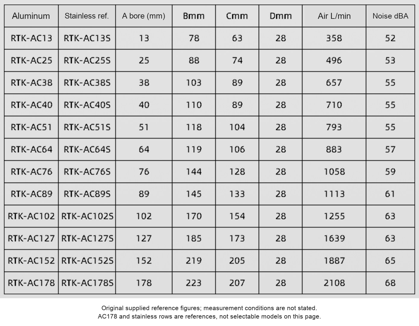
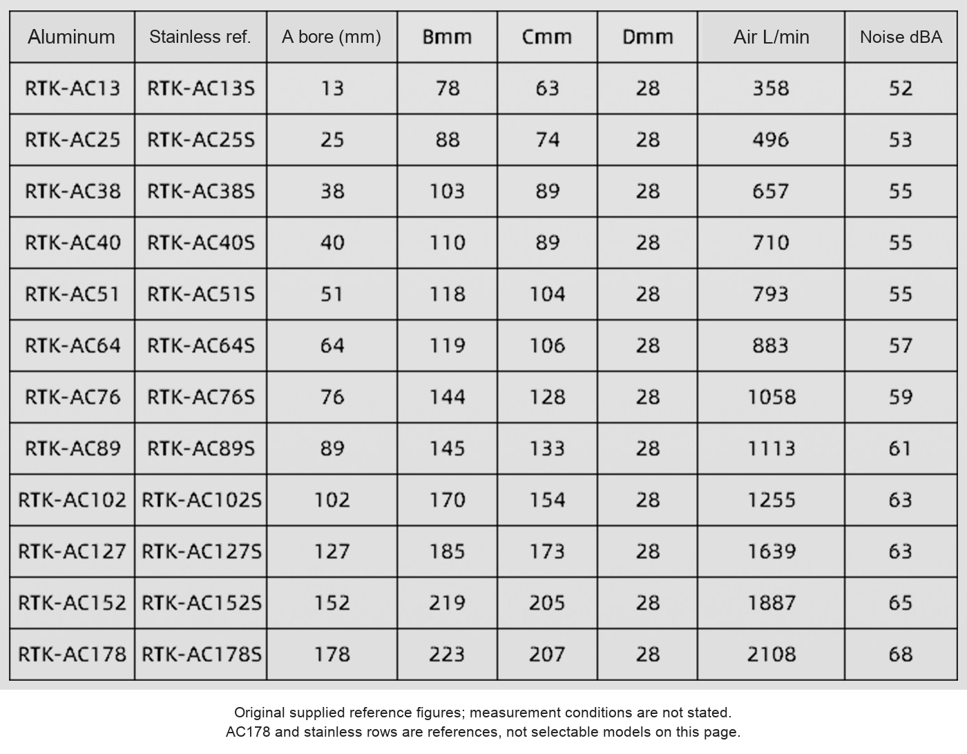
| Model | A bore mm (in) | B outside mm (in) | C mounting mm (in) | D thick mm (in) | Air L/min | Noise dBA |
|---|---|---|---|---|---|---|
| AC13 | 13 (0.512) | 78 (3.071) | 63 (2.480) | 28 (1.102) | 358 | 52 |
| AC25 | 25 (0.984) | 88 (3.465) | 74 (2.913) | 28 (1.102) | 496 | 53 |
| AC38 | 38 (1.496) | 103 (4.055) | 89 (3.504) | 28 (1.102) | 657 | 55 |
| AC40 | 40 (1.575) | 110 (4.331) | 89 (3.504) | 28 (1.102) | 710 | 55 |
| AC51 | 51 (2.008) | 118 (4.646) | 104 (4.094) | 28 (1.102) | 793 | 55 |
| AC64 | 64 (2.520) | 119 (4.685) | 106 (4.173) | 28 (1.102) | 883 | 57 |
| AC76 | 76 (2.992) | 144 (5.669) | 128 (5.039) | 28 (1.102) | 1058 | 59 |
| AC89 | 89 (3.504) | 145 (5.709) | 133 (5.236) | 28 (1.102) | 1113 | 61 |
| AC102 | 102 (4.016) | 170 (6.693) | 154 (6.063) | 28 (1.102) | 1255 | 63 |
| AC127 | 127 (5.000) | 185 (7.283) | 173 (6.811) | 28 (1.102) | 1639 | 63 |
| AC152 | 152 (5.984) | 219 (8.622) | 205 (8.071) | 28 (1.102) | 1887 | 65 |
A, B, C and D follow the letters in the original dimension drawing. C is retained as the supplied mounting dimension; confirm its exact geometry on the selected model drawing. The reference image additionally shows AC178 and stainless equivalents, but only the thirteen priced aluminum models above are offered. Do not substitute a reference-table row for an unlisted model.
Air Connection and Supply
The supplied attributes specify a 1/4-inch NPT air interface and a 6.9 bar working reference (0.69 MPa, approximately 100 psi). Confirm the connector and tubing supplied for the chosen size. The photos show typical push-in fittings and an external connecting tube. Air consumption and noise values above come from the source table; its test distance and full measurement conditions are not stated. Confirm compressor capacity at the operating point and use appropriate regulation and filtration.
Split Body and Mounting
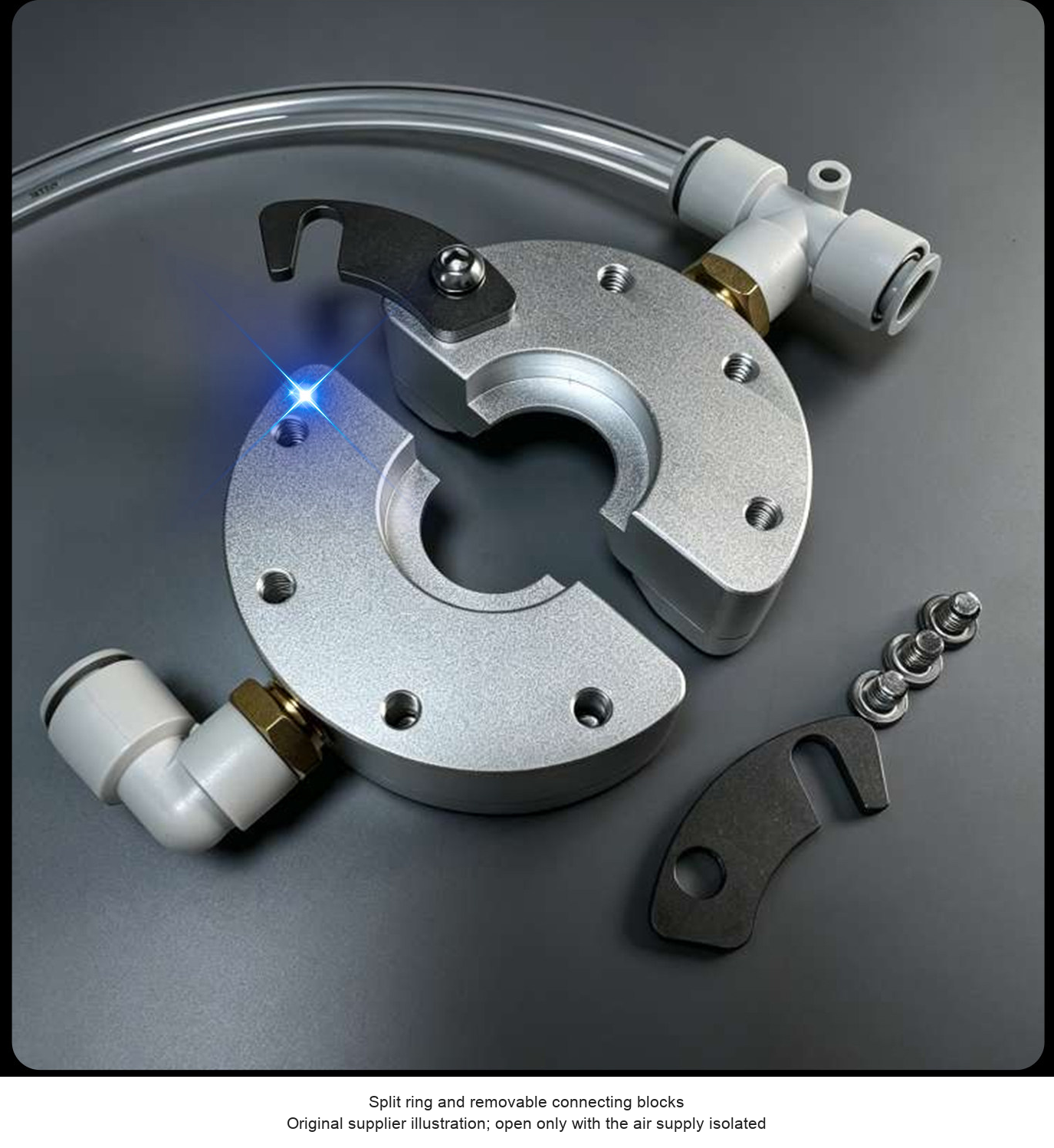
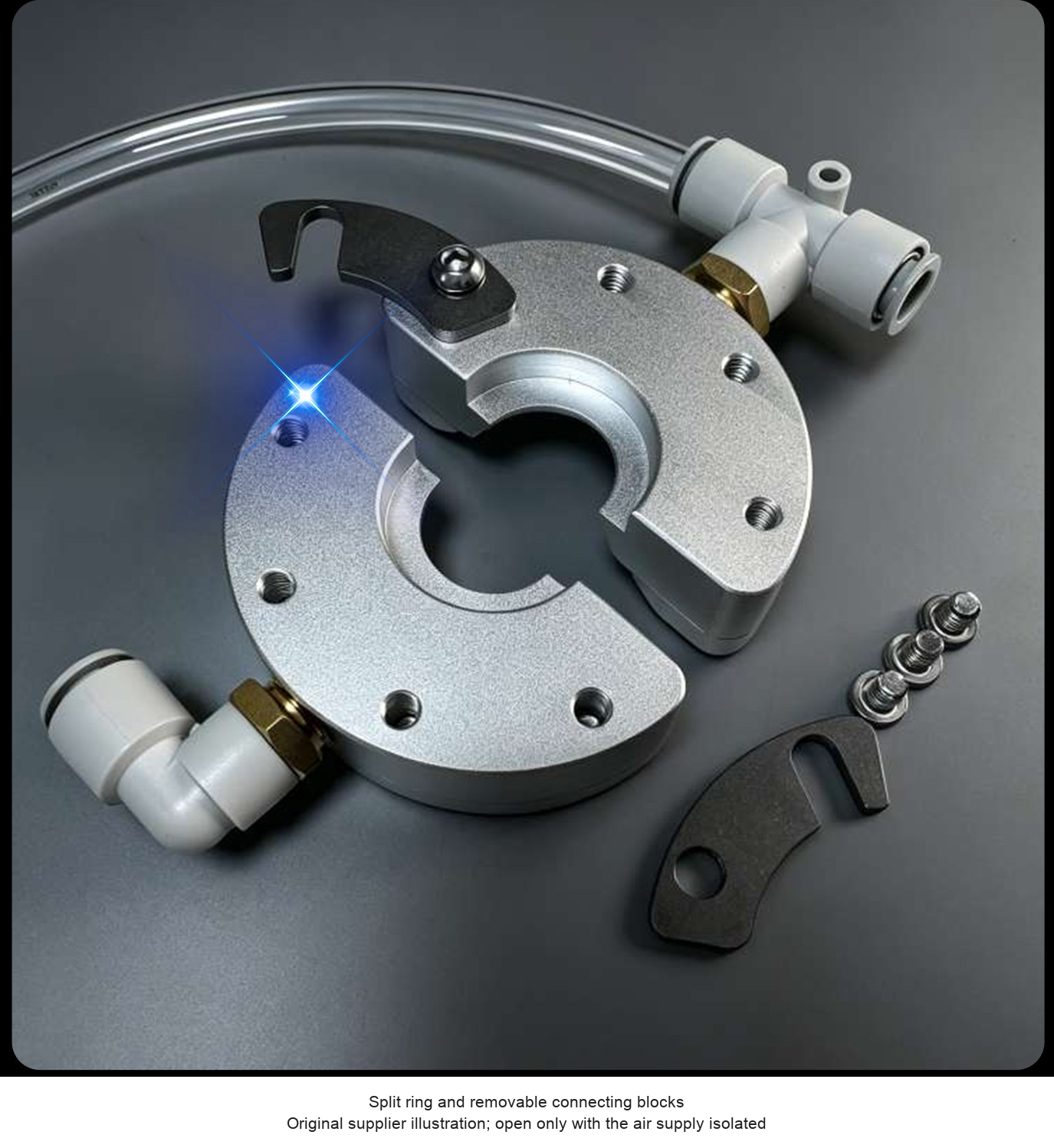
The original close-up marks four M6 mounting holes and removable connecting blocks. Treat that view as a family reference and request the size-specific mounting layout before drilling. The split structure allows installation around suitable continuous material without drawing its full length through a closed ring. Secure the body without distortion and keep the outlet clean and clear.
Installation and Process Adjustment
- Measure the maximum workpiece diameter or section, allowing suitable clearance and process movement.
- Confirm A/B/C/D dimensions, mounting arrangement, inlet thread, air delivery and line speed for the selected model.
- Isolate the air supply before opening the split body or adjusting fittings. Fit and secure the ring around the intended path.
- Align the workpiece through the opening without contact. Arrange runoff and debris collection for the direction of blow-off.
- Connect the controlled air supply and begin at a suitable setting. Check the actual surface, required dryness and process speed.
- Recheck mounting, connections and outlet cleanliness. Isolate and depressurize before cleaning or dismantling.
Included-Item Check and Selection Help
One chosen aluminum ring air wiper configuration. An air-line connector is named as a standard accessory; confirm fitting and connecting-tube contents before ordering. Compressor, filter/regulator, mounting bracket, production line and workpieces are not specified as included. No certified alloy grade, maximum temperature or finished-surface result is established by the supplied listing.
For a selection check, send model, workpiece shape/diameter, line speed, liquid or debris to remove, air pressure/flow and a mounting sketch to boltte@boltte.com. Confirm dimensions before ordering AC10 or AC32.
Original Product, Drawing and Application Images
The original clear family views, split structure, mounting detail, dimension drawing, numerical table, principle schematic and application examples are retained below. Original product geometry is preserved; English captions replace supplier promotional text.




Model / configuration / SKU
| Model / configuration | SKU |
|---|---|
| AC10 - Confirm dimensions | 5143401718517 |
| AC13 - ID 13 mm (0.512 in) | 5143401718518 |
| AC25 - ID 25 mm (0.984 in) | 5143401718519 |
| AC32 - Confirm dimensions | 5143401718520 |
| AC38 - ID 38 mm (1.496 in) | 5143401718521 |
| AC40 - ID 40 mm (1.575 in) | 5143401718522 |
| AC51 - ID 51 mm (2.008 in) | 5143401718516 |
| AC64 - ID 64 mm (2.520 in) | 6083649296841 |
| AC76 - ID 76 mm (2.992 in) | 6083649296845 |
| AC89 - ID 89 mm (3.504 in) | 6083649296842 |
| AC102 - ID 102 mm (4.016 in) | 6083649296843 |
| AC127 - ID 127 mm (5.000 in) | 6083649296846 |
| AC152 - ID 152 mm (5.984 in) | 6083649296844 |