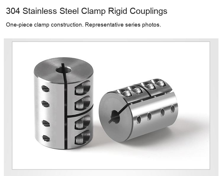
304 Stainless Steel One-Piece Clamp Rigid Shaft Couplings
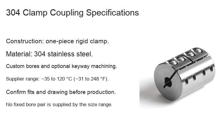
Rigid shaft couplings with a one-piece clamping body and socket-head fasteners. Select an outside diameter and overall length, then confirm the finished bore dimensions for both shafts. The listed bore range is a custom machining scope, not a fixed supplied bore pair.
Custom Ordering
Provide both shaft diameters d1 and d2, bore tolerances, engagement lengths and the final drawing in Order requirements or contact BOLTTE. Confirm the manufacturing specification before production. Custom processing time is confirmed separately from shipping transit estimates.
Material and Keyway
- 304 stainless steel is identified in the dimensional offers and supplier product specification.
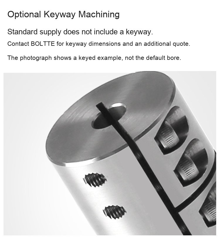
- Standard supply does not include a keyway. Keyway machining is optional and requires dimensional confirmation and a separate quotation before ordering.
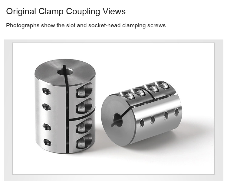
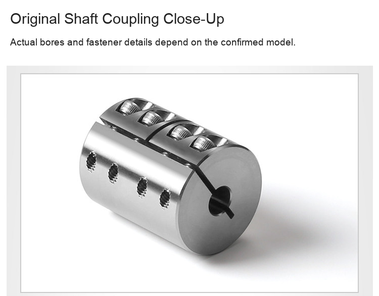
- The original photos show a keyed example; this does not mean a keyway is included in every offer.
- Supplier-listed temperature range: −35 to 120 °C (−31 to 248 °F). Check the actual duty and supplied assembly.
Model Size Guide
D and L identifiers below denote outside diameter and overall length. Millimetres are authoritative; inch equivalents are rounded to three decimals.
| Size | OD × length (mm / in) | Custom bore range (mm / in) |
|---|---|---|
| D32L32 | 32 × 32 / 1.260 × 1.260 | 6–16 / 0.236–0.630 |
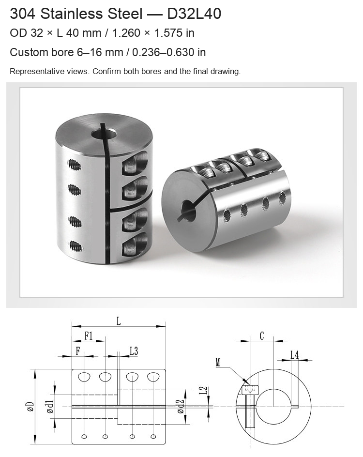
| D32L40 | 32 × 40 / 1.260 × 1.575 | 6–16 / 0.236–0.630 |
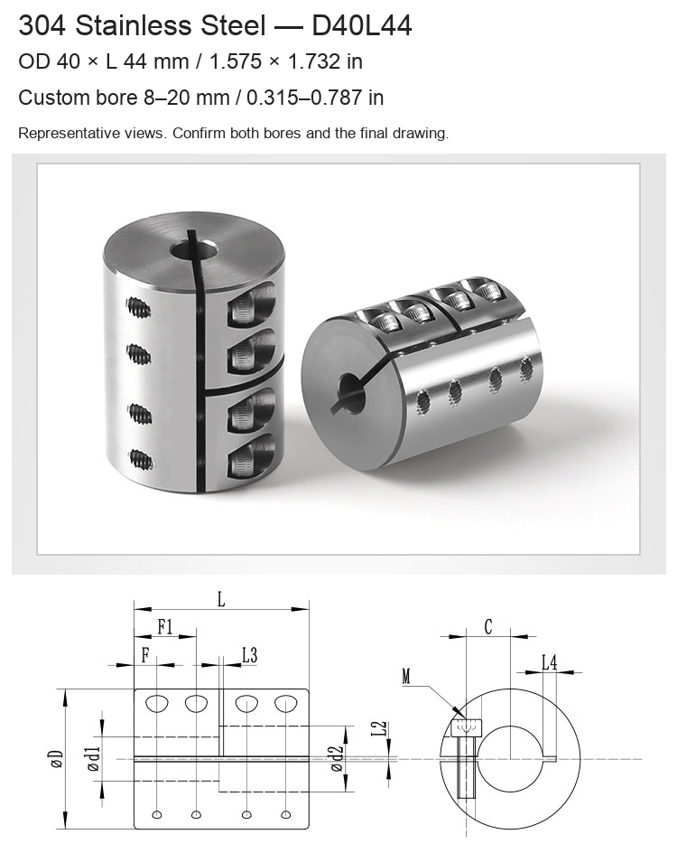
| D40L44 | 40 × 44 / 1.575 × 1.732 | 8–20 / 0.315–0.787 |
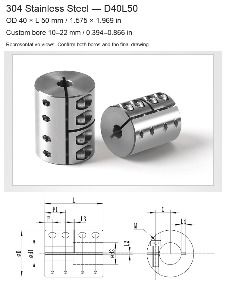
| D40L50 | 40 × 50 / 1.575 × 1.969 | 10–22 / 0.394–0.866 |
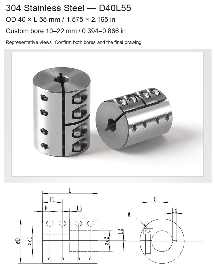
| D40L55 | 40 × 55 / 1.575 × 2.165 | 10–22 / 0.394–0.866 |
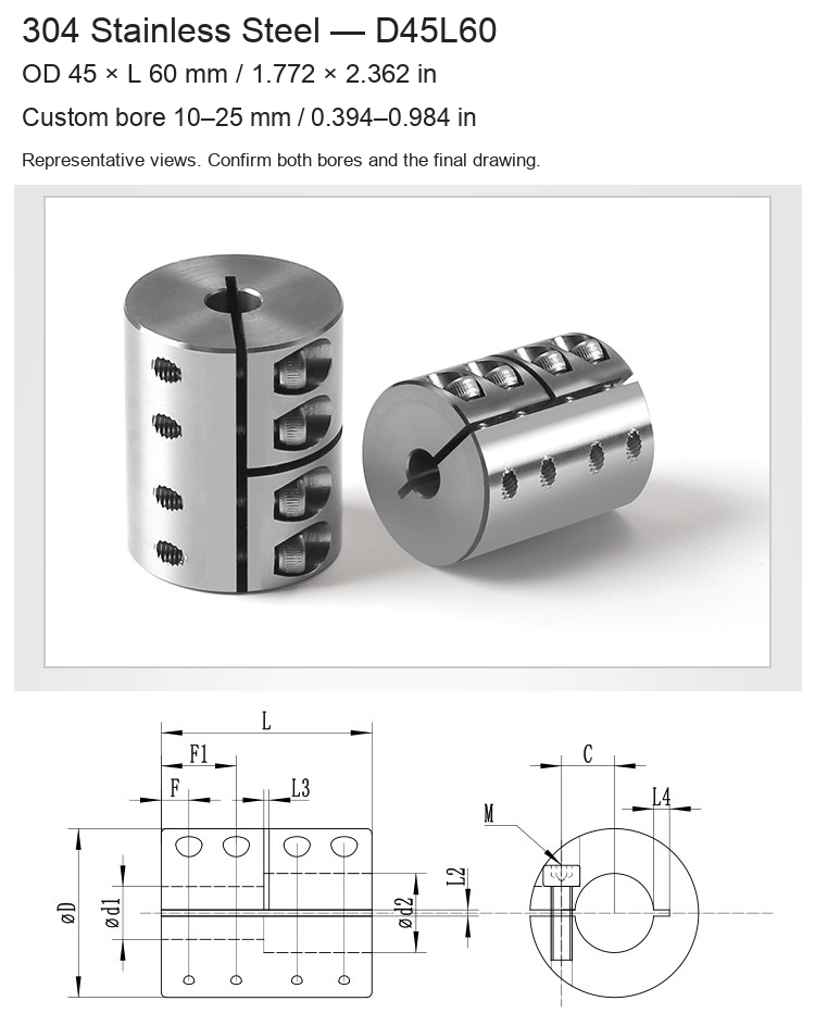
| D45L60 | 45 × 60 / 1.772 × 2.362 | 10–25 / 0.394–0.984 |
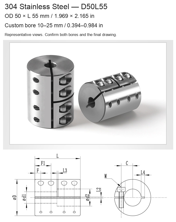
| D50L55 | 50 × 55 / 1.969 × 2.165 | 10–25 / 0.394–0.984 |
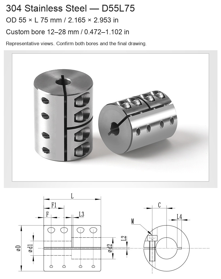
| D55L75 | 55 × 75 / 2.165 × 2.953 | 12–28 / 0.472–1.102 |
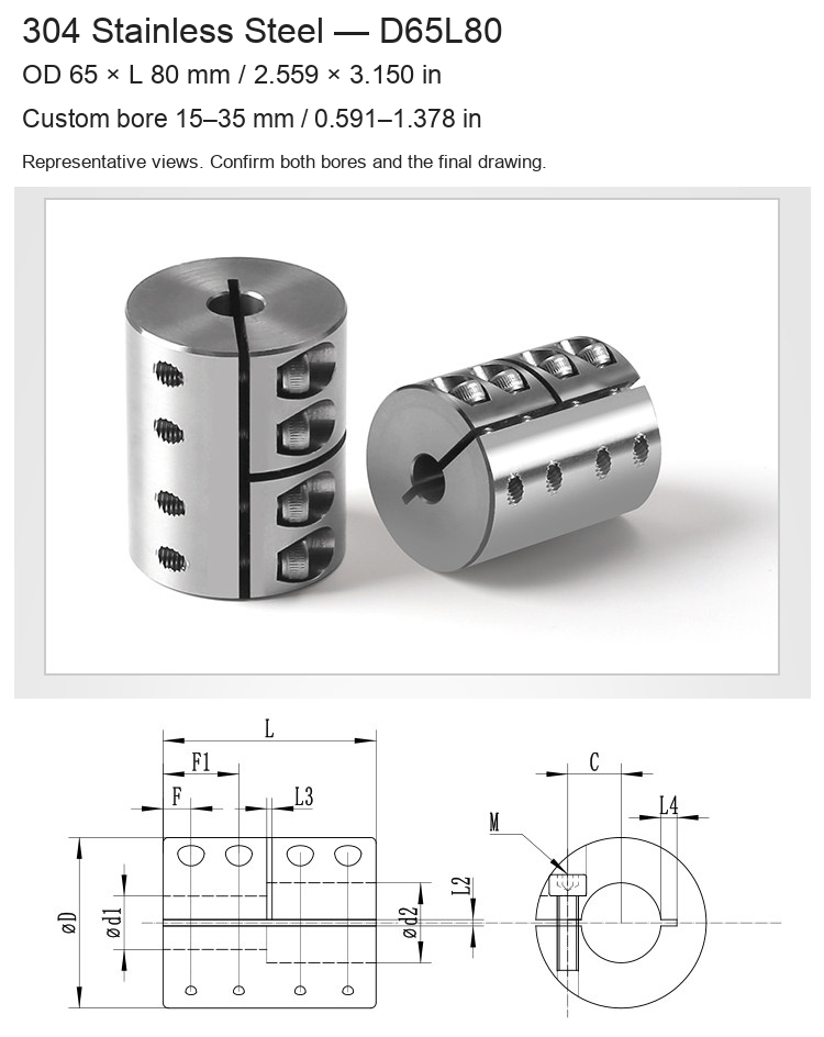
| D65L80 | 65 × 80 / 2.559 × 3.150 | 15–35 / 0.591–1.378 |
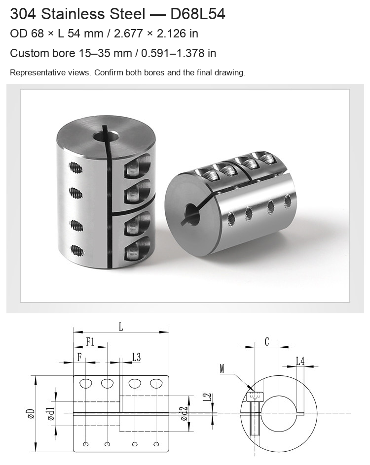
| D68L54 | 68 × 54 / 2.677 × 2.126 | 15–35 / 0.591–1.378 |
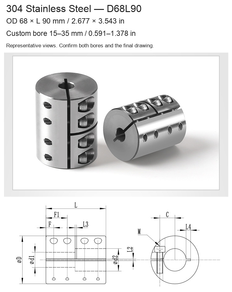
| D68L90 | 68 × 90 / 2.677 × 3.543 | 15–35 / 0.591–1.378 |
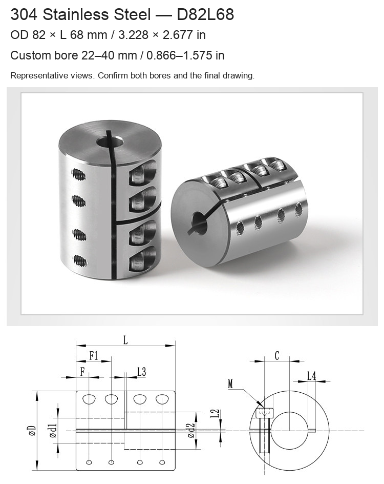
| D82L68 | 82 × 68 / 3.228 × 2.677 | 22–40 / 0.866–1.575 |
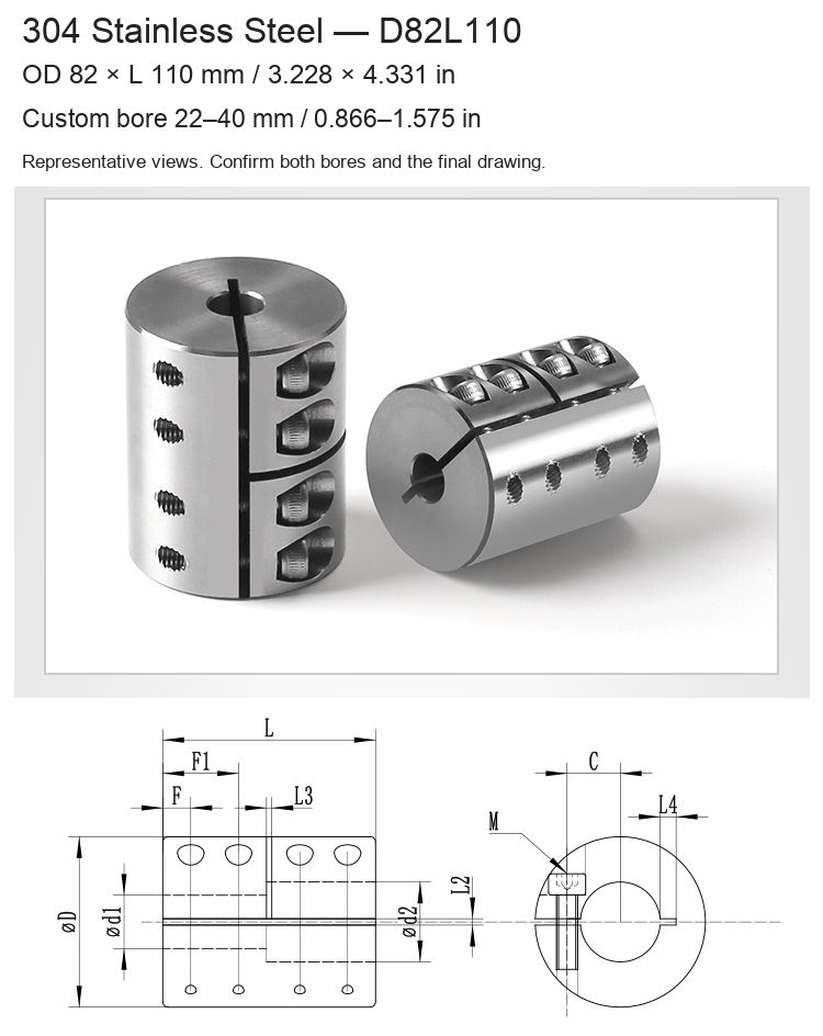
| D82L110 | 82 × 110 / 3.228 × 4.331 | 22–40 / 0.866–1.575 |
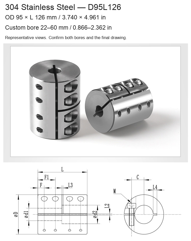
| D95L126 | 95 × 126 / 3.740 × 4.961 | 22–60 / 0.866–2.362 |
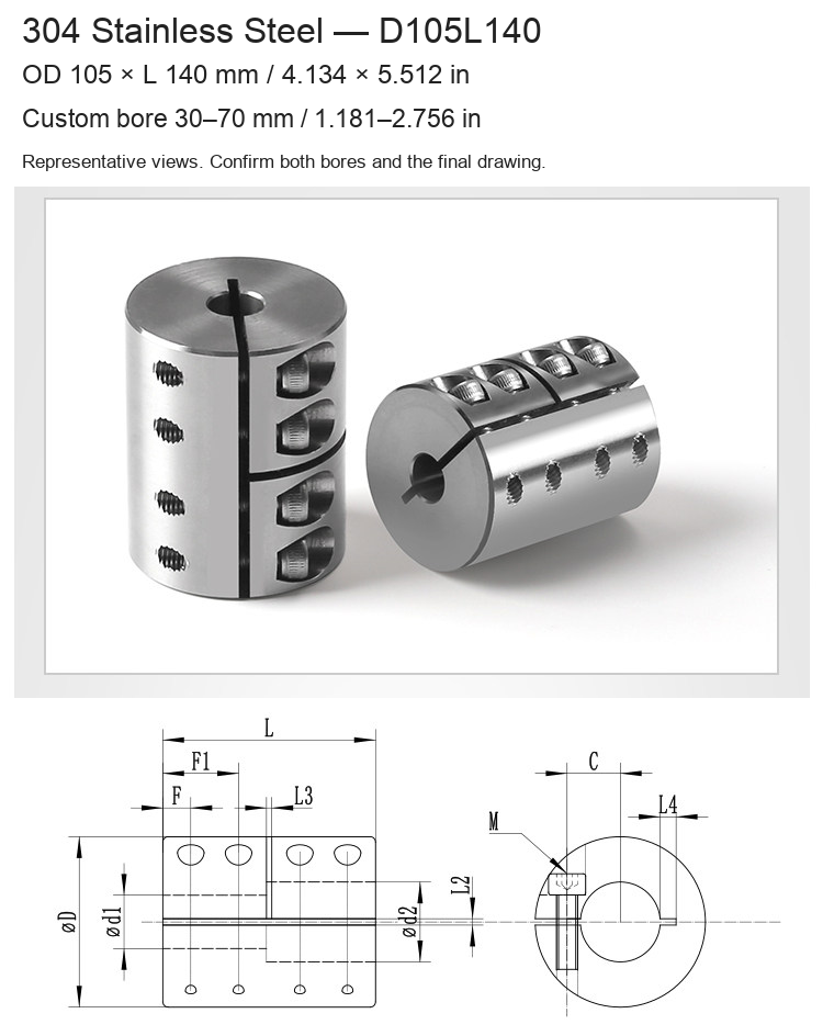
| D105L140 | 105 × 140 / 4.134 × 5.512 | 30–70 / 1.181–2.756 |
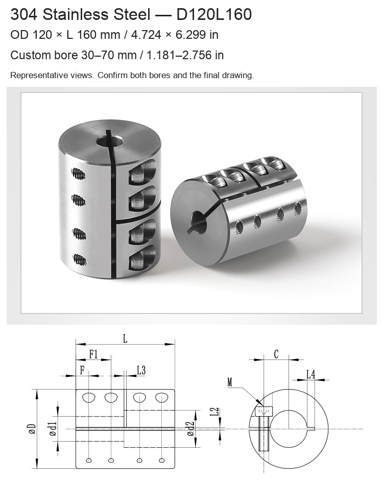
| D120L160 | 120 × 160 / 4.724 × 6.299 | 30–70 / 1.181–2.756 |
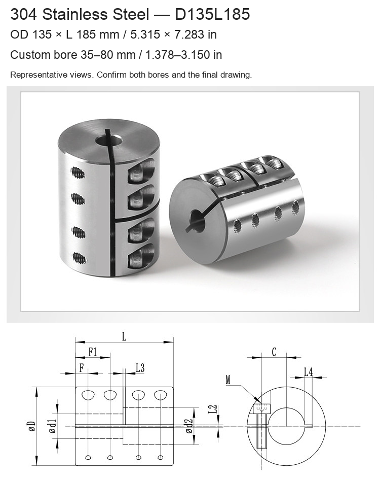
| D135L185 | 135 × 185 / 5.315 × 7.283 | 35–80 / 1.378–3.150 |
Original Drawing and Construction
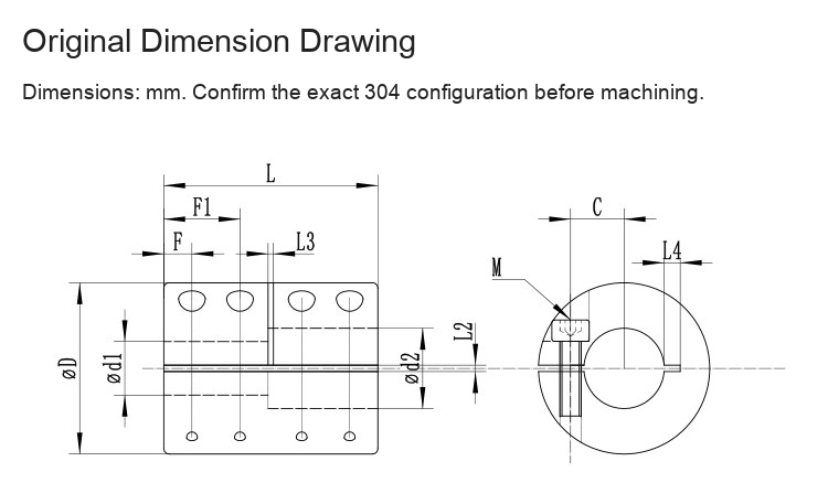
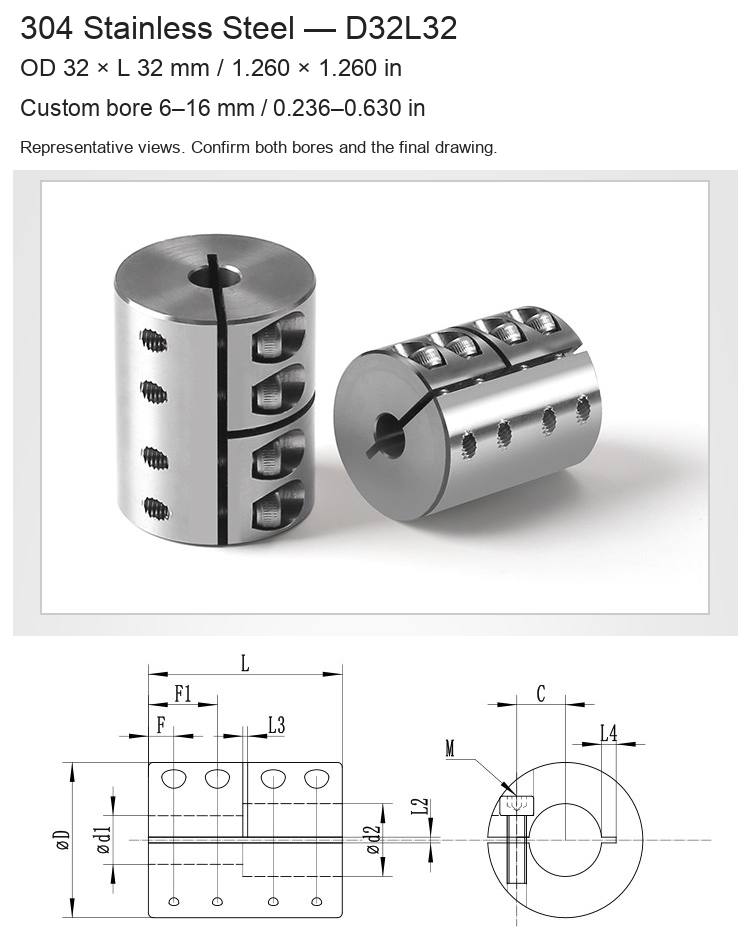
The original drawing shows diameter D, overall length L, bores d1/d2, clamping slots and fastener/spacing features M, F/F1, L2/L3/L4 and C. It illustrates dimension notation, not a completed drawing for every selectable 304 configuration. Confirm the exact applicable drawing before machining.
This is a rigid clamp connection, not an elastic coupling or a fully separable two-piece split body. Align both shafts accurately and check installation access. No verified torque, rotational-speed, concentricity or misalignment rating is specified for these 304 offers.
Selection and Installation
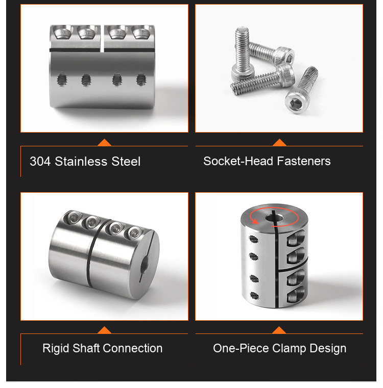
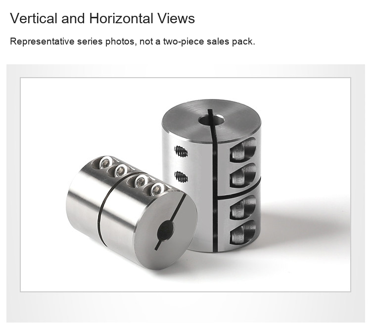
Check shaft sizes, fits, clamping screw clearance, installation space and operating environment. Isolate equipment before installation and follow the fastening and inspection requirements for the confirmed assembly. Do not apply ratings from a different material or coupling structure. Original series photographs retain product geometry; multiple views do not establish a two-piece sales pack. Shafts and motors are not included.