TL 45-Steel Elastic-Sleeve Pin Couplings
Made-to-order shaft couplings with 45-steel hubs and polyurethane elastic sleeves. Choose a listed TL model and confirm the finished connection dimensions for both shafts. The bore range is the custom machining scope, not a fixed supplied bore pair.
Custom Ordering
Provide d1 and d2, bore tolerances, keyways, engagement lengths, shaft-end form and a drawing or sample specification in Order requirements or contact BOLTTE. Confirm the manufacturing drawing before production. Processing time is confirmed separately from any shipping transit estimate. Requirements outside the listed model scope need separate confirmation before ordering.
Availability
TL3 and TL4 are currently unavailable for online ordering. Contact BOLTTE to confirm supply. Other listed models are offered with custom-bore confirmation before production.
Construction
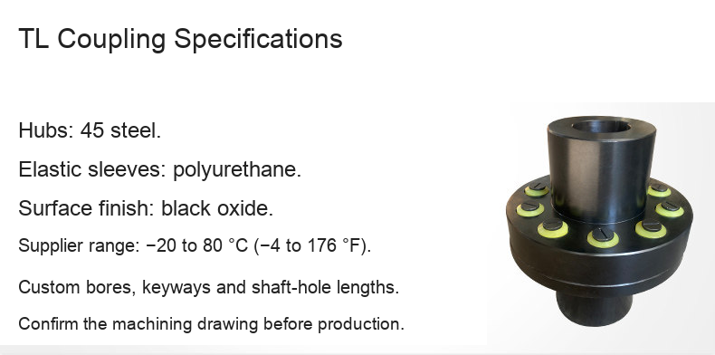
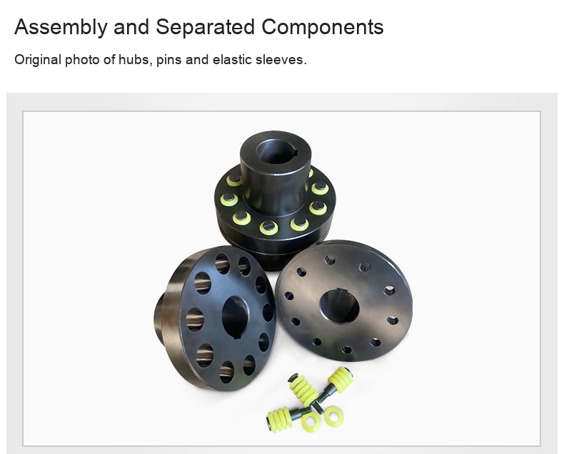
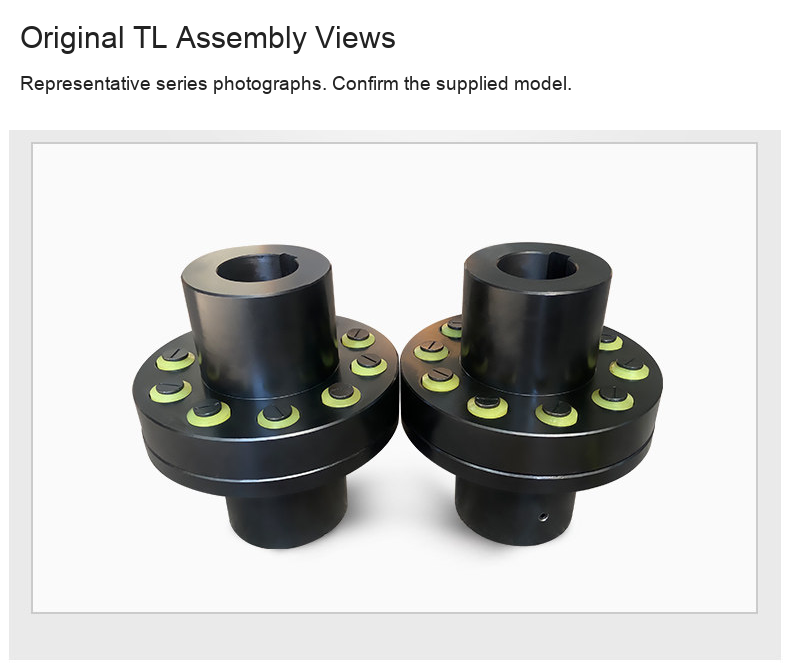
- Two flanged steel hubs connected by pins with polyurethane elastic sleeves.
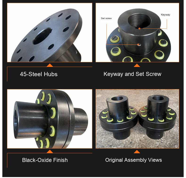
- 45-steel hubs and black-oxide surface treatment identified in the supplied specification.
- Supplier-listed temperature range −20 to 80 °C (−4 to 176 °F). Check the actual duty and supplied assembly.
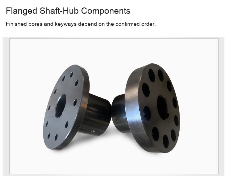
- Keyway and set-screw features shown in the original photographs must match the confirmed machining drawing.
Listed Model Dimensions
Millimetres are authoritative. Inch equivalents are rounded to three decimals.
| Model | Outside diameter (mm / in) | Custom bore range (mm / in) |
|---|---|---|
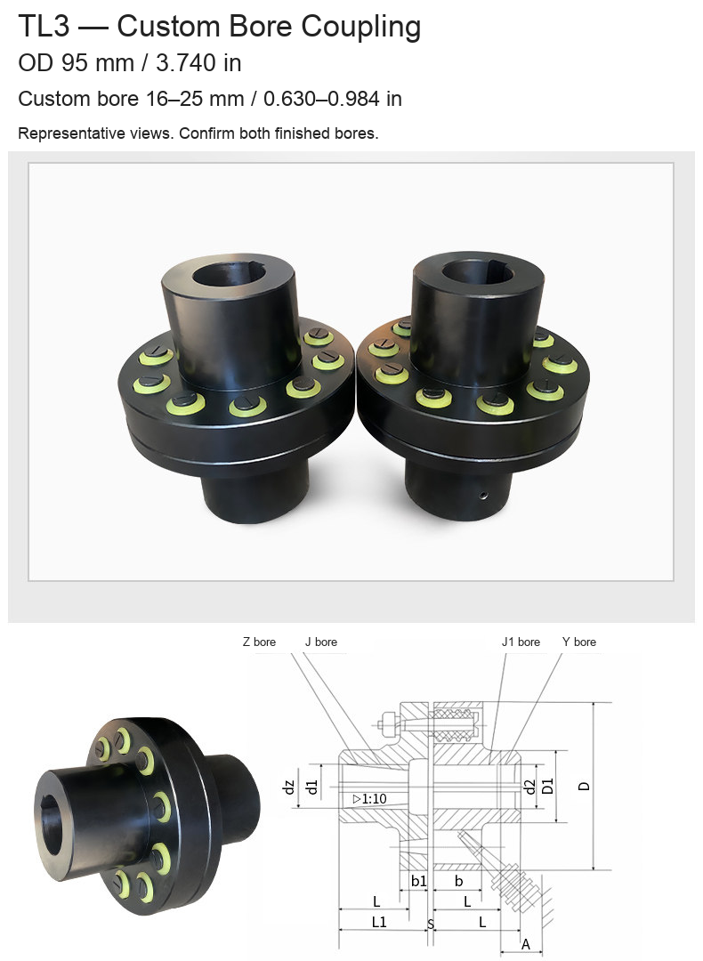
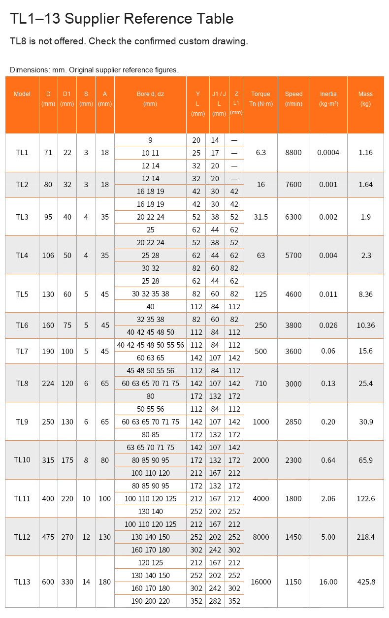
| TL3 | 95 / 3.740 | 16–25 / 0.630–0.984 |
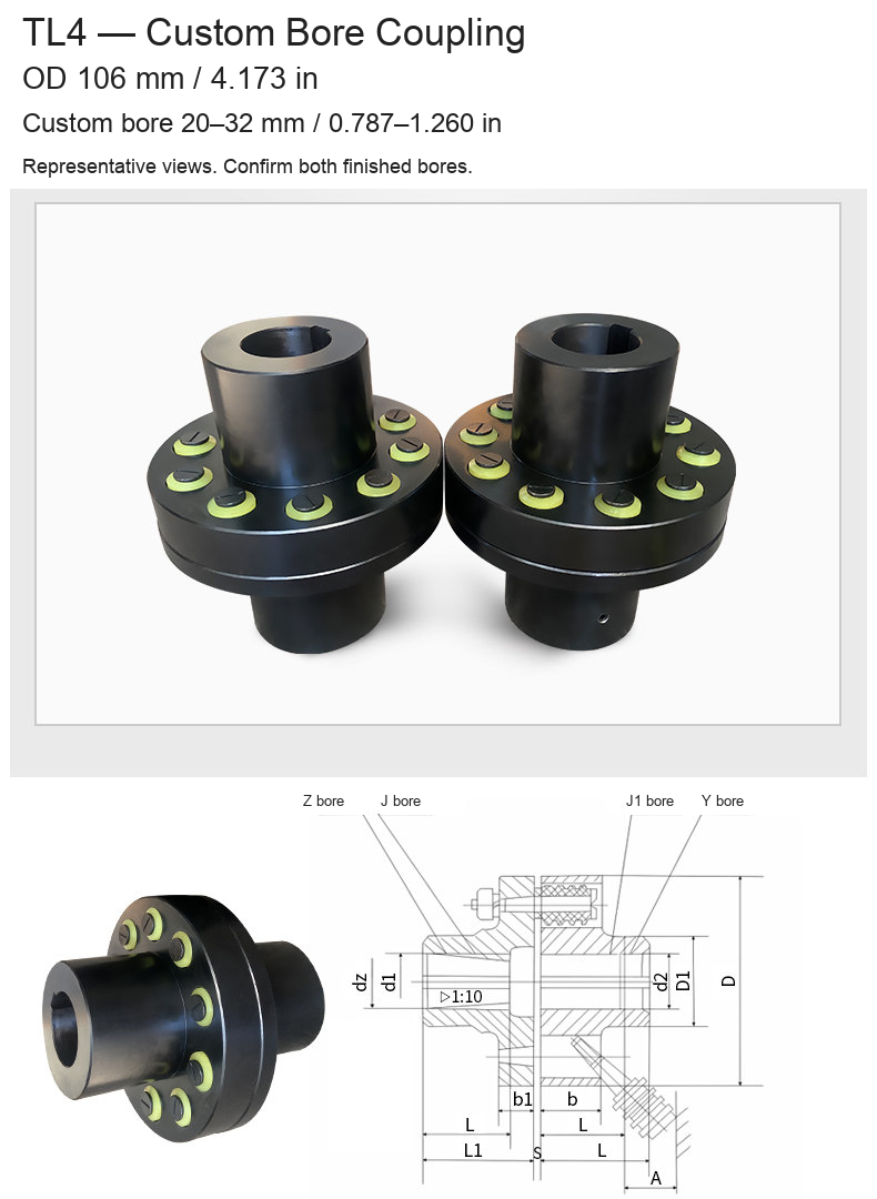
| TL4 | 106 / 4.173 | 20–32 / 0.787–1.260 |
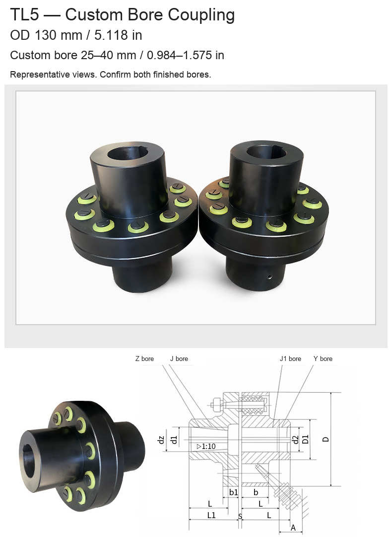
| TL5 | 130 / 5.118 | 25–40 / 0.984–1.575 |
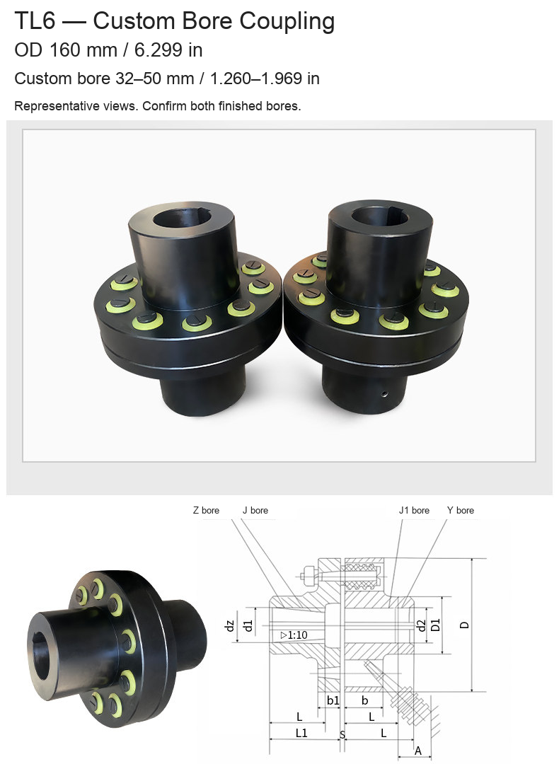
| TL6 | 160 / 6.299 | 32–50 / 1.260–1.969 |
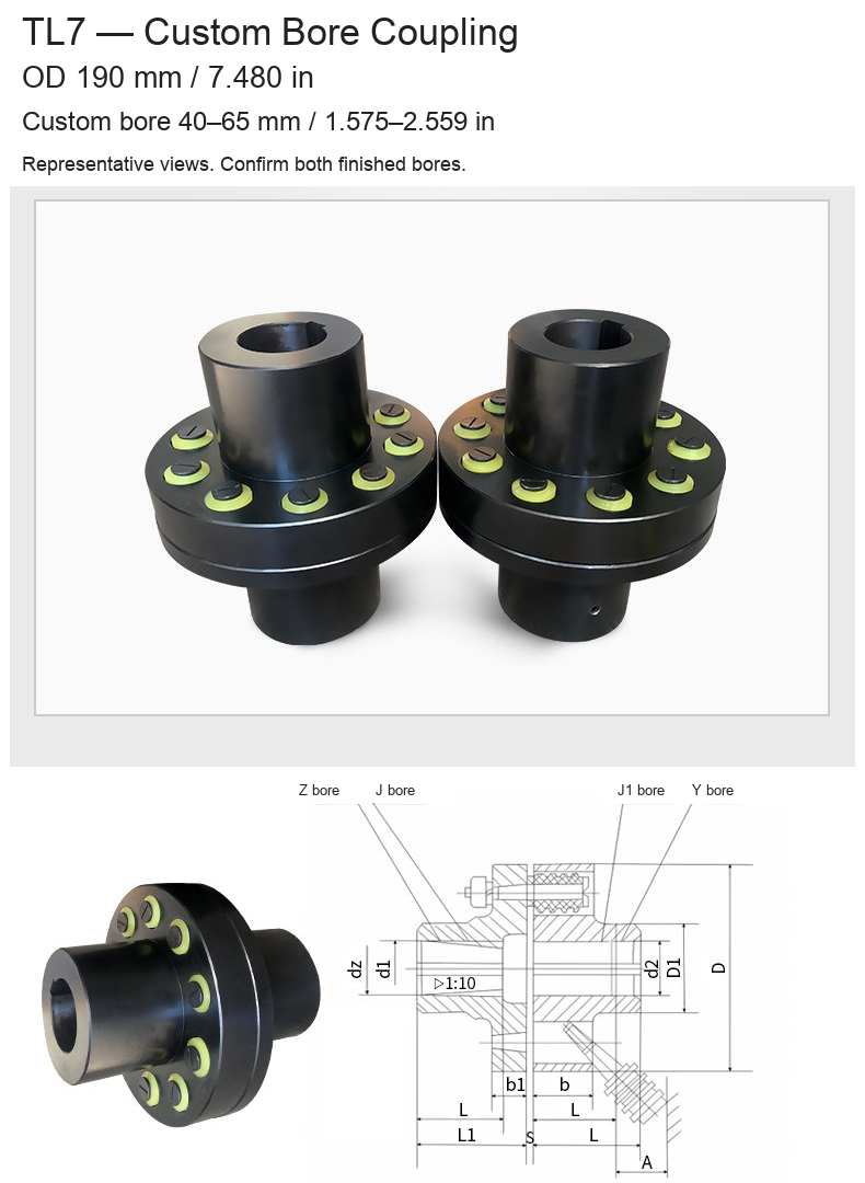
| TL7 | 190 / 7.480 | 40–65 / 1.575–2.559 |
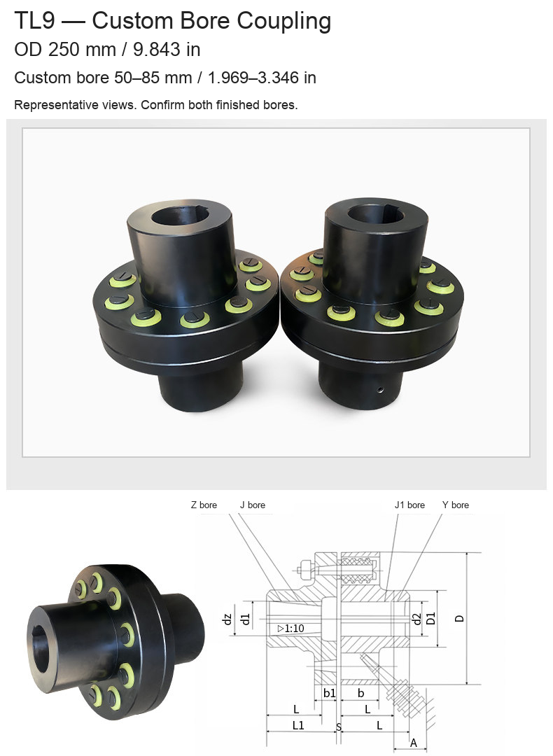
| TL9 | 250 / 9.843 | 50–85 / 1.969–3.346 |
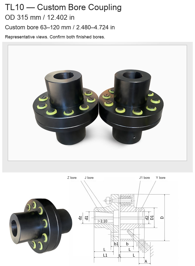
| TL10 | 315 / 12.402 | 63–120 / 2.480–4.724 |
Drawing and Reference Data
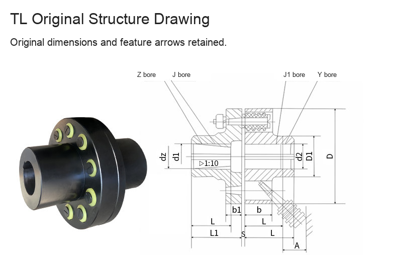
The original drawing retains D/D1, d1/d2/dz, L/L1, S, A and b/b1 dimension labels and the original feature leaders. Z, J, J1 and Y mark shaft-hole forms. Confirm the relevant bore and engagement-length combination for the actual assembly.
The original numerical reference table gives nominal torque Tn in N·m, speed in r/min, rotational inertia in kg·m² and mass in kg. TL1, TL2, TL8 and TL11–13 are reference entries, not selectable offers on this page. In particular, TL8 is not offered pending dimensional confirmation. Reference figures are not an independent test certificate and must be checked against the confirmed configuration.
Selection and Installation
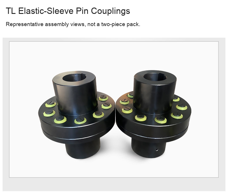
Confirm torque, speed, shaft fits, keyways, alignment and available installation space. Isolate equipment before assembly. Follow the fastening and elastic-sleeve inspection or replacement requirements for the supplied assembly. No universal interchangeability, numerical misalignment allowance or maintenance-free rating is specified. Photos retain the original product and component views; multiple assemblies in one photograph do not imply a two-piece sales pack. Motors and shafts are not included.
Modelo / configuración / SKU
| Modelo / configuración | SKU |
|---|---|
| TL5 / OD 130 mm (5.118 in) / Custom Bore 25–40 mm (0.984–1.575 in) | 5331032824319 |
| TL6 / OD 160 mm (6.299 in) / Custom Bore 32–50 mm (1.260–1.969 in) | 5331032824320 |
| TL7 / OD 190 mm (7.480 in) / Custom Bore 40–65 mm (1.575–2.559 in) | 5331032824321 |
| TL9 / OD 250 mm (9.843 in) / Custom Bore 50–85 mm (1.969–3.346 in) | 5331032824323 |
| TL10 / OD 315 mm (12.402 in) / Custom Bore 63–120 mm (2.480–4.724 in) | 5331032824324 |
| TL3 / OD 95 mm (3.740 in) / Custom Bore 16–25 mm (0.630–0.984 in) | 5331032824317 |
| TL4 / OD 106 mm (4.173 in) / Custom Bore 20–32 mm (0.787–1.260 in) | 5331032824318 |