


Locking Gravity Water Fillers for RV Water Tanks
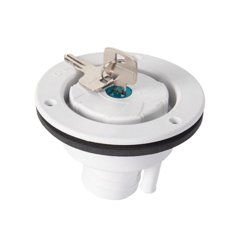
Round plastic tank-fill assemblies with a removable locking cap, an inlet spigot and a separate vent connection. Choose Style A or Style B and a white or black finish. Front and rear photographs show opposite sides of one unit. Each option supplies one selected filler assembly with its cap and the two keys described in the source.
Model Options
| Model | Style / finish | Pictured water / vent spigots |
|---|---|---|
| SFWI1-02 | A / White | 28 mm / 1.102 in water;10 mm / 0.394 in vent |
| SFWI2-02 | A / Black | 28 mm / 1.102 in water;10 mm / 0.394 in vent |
| SFGF1-01 | B / White | 40 mm / 1.575 in water;10 mm / 0.394 in vent |
| SFGF2-01 | B / Black | 40 mm / 1.575 in water;10 mm / 0.394 in vent |
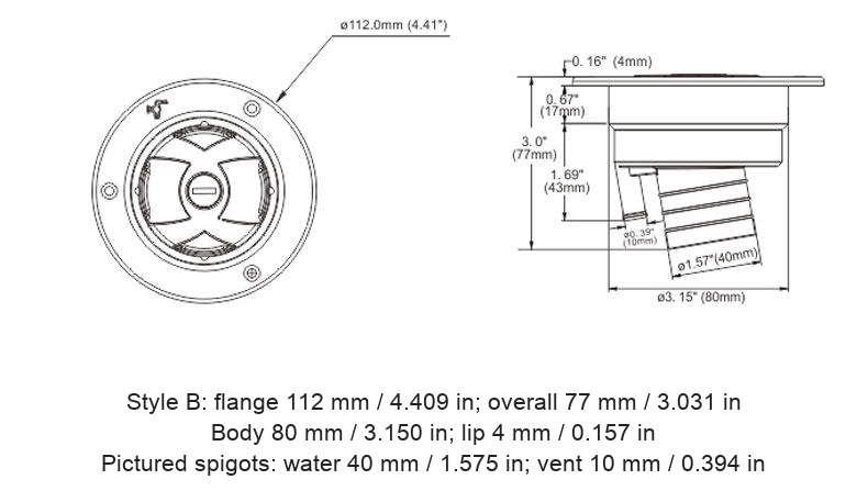
The Style B source order name uses 38 mm, while both its photograph and original drawing mark a 40 mm spigot. This listing retains that distinction and does not promise a 38 mm outside diameter or a particular hose fit. Use the pictured/drawn dimensions and confirm the actual hose and clamp before ordering. The feature copy also uses a nominal vent description; the supplied spigot photographs mark 10 mm, which is the dimensional reference shown here.
Original Mounting References
| Reference | Style A | Style B |
|---|---|---|
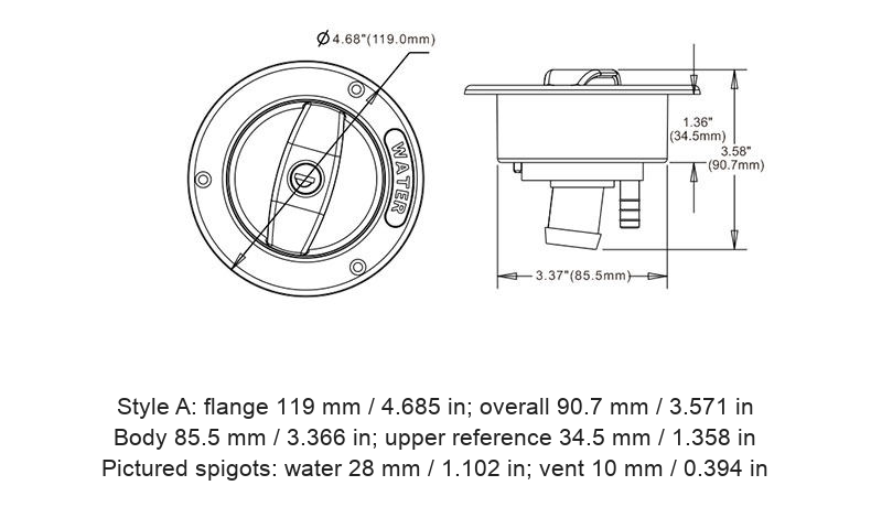
| Outer flange | 119 mm / 4.685 in | 112 mm / 4.409 in |
| Overall depth | 90.7 mm / 3.571 in | 77 mm / 3.031 in |
| Body-width reference | 85.5 mm / 3.366 in | 80 mm / 3.150 in |
| Other drawing references | 34.5 mm / 1.358 in upper housing | 4 mm / 0.157 in lip;17 mm / 0.669 in upper and43 mm / 1.693 in lower reference |
The original engineering lines, cap orientation and screw-hole locations are retained in the model-bound drawings. Added inch equivalents are calculated from metric values to three decimals; some original inch labels use different rounding. Body dimensions are not an independently confirmed installation-cutout specification. Check the actual part, mounting thickness, screw clearance, hose routing and seal before drilling.
Parts and Function
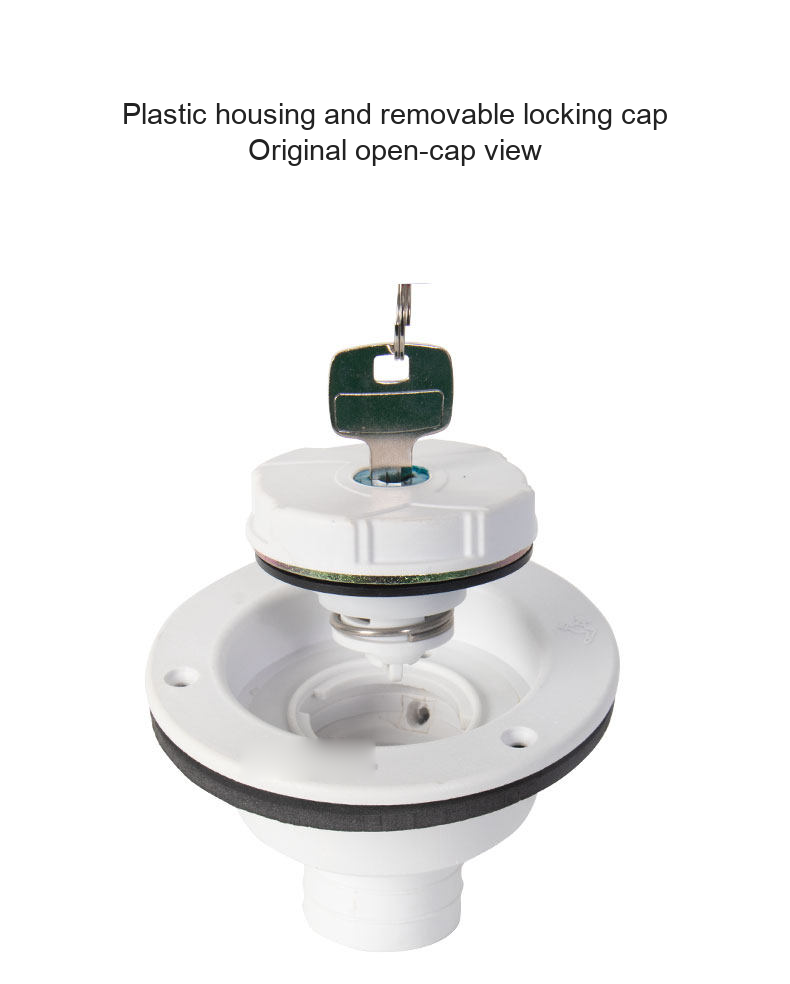
The cap provides a keyed closure for the gravity-fill opening. A lock can limit casual access; it is not a water-purity guarantee. The pictured assemblies include a plastic body and a cap seal/gasket, with the separate rear water and vent spigots shown in the photographs. Keep the vent path clear so displaced tank air can escape during filling. No pressure regulator or city-water pressure inlet is included or implied.
The RV sketch illustrates the positions of different water-system components. The city-water inlet and check valve shown in that sketch are separate components, not additional items in this order. Tanks, hoses, hose clamps, mounting screws and sealant are not included unless expressly identified in the selected option.
Installation and Use
- Confirm the selected model, finish and all physical dimensions against the vehicle and tank layout. Isolate the system as required before fitting.
- Fit the mounting flange to a suitable supported surface with a compatible gasket/sealing method and appropriate fasteners. Do not deform the plastic flange or over-tighten the screws.
- Connect the water hose and separate vent hose to the correct spigots. Support both hoses, use matching clamps and avoid kinks or trapped low sections in the vent routing.
- Unlock and remove the cap as its mechanism requires. Fill through a suitable gravity-fill hose while supervising the tank level and keeping the vent unobstructed.
- Stop filling before overflow, check for leakage, refit the cap and test the lock. Store the keys where they can be retrieved for future service.
Cleaning and Ordering Notes
Inspect the cap seal, housing, lock and hose joints regularly. Use cleaning methods compatible with the plastic, seal and tank system, and follow the vehicle/tank instructions for hygiene and winter draining. No working-pressure rating, freeze protection, UV service life, liquid-temperature limit or drinking-water certification is established by the supplied material. These are gravity tank fillers; do not substitute them for a pressurized city-water inlet.
Original product and open-cap photographs are retained below. For a cutout drawing, exact hose fit, replacement key/cap compatibility or material confirmation, contact boltte@boltte.com.




Modelo / configuración / SKU
| Modelo / configuración | SKU |
|---|---|
| SFWI1-02 / Style A / White | 4061734730862 |
| SFWI2-02 / Style A / Black | 4061734730863 |
| SFGF1-01 / Style B / White | 4409796140233 |
| SFGF2-01 / Style B / Black | 4409796140234 |