



RTK-VTL15-40 Adjustable Vortex Cold Air Guns
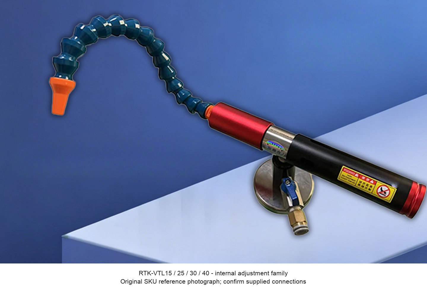
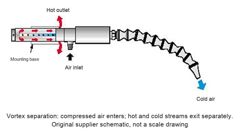
These compressed-air cooling guns use vortex separation to produce a directed cold stream for localized industrial cooling and blow-off. A positionable segmented hose directs air toward the working area, while the hot stream exhausts separately. A magnetic mounting base and a base-mounted flow valve are shown in the supplied family photographs. An external compressed-air supply is required.
Select Internal or External Adjustment
| Model | Adjustment reference | Original USD | Sale USD |
|---|---|---|---|
| RTK-VTL15 | Internal | 1180 | 944.00 |
| RTK-VTL25 | Internal | 1180 | 944.00 |
| RTK-VTL30 | Internal | 1180 | 944.00 |
| RTK-VTL40 | Internal | 1180 | 944.00 |
| RTK-VTL15X | External | 1250 | 1000.00 |
| RTK-VTL25X | External | 1250 | 1000.00 |
| RTK-VTL30X | External | 1250 | 1000.00 |
| RTK-VTL40X | External | 1250 | 1000.00 |
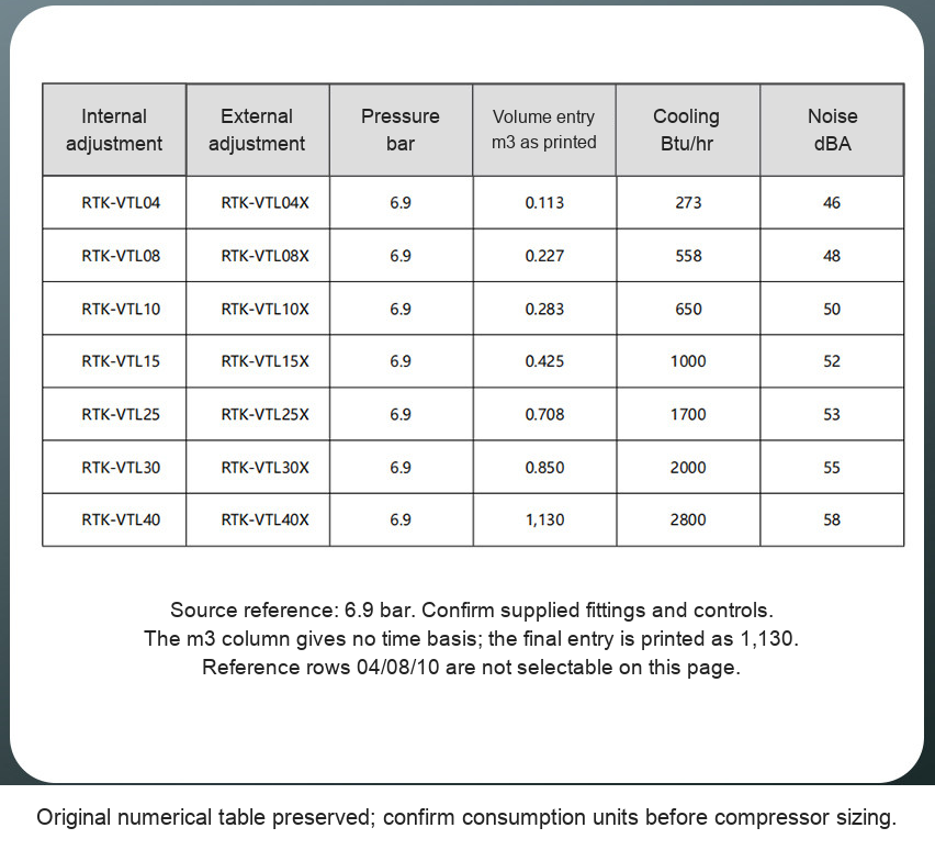
The supplier comparison table distinguishes internal-adjustment models without X and external-adjustment models ending in X. The source SKU photographs are shared family views rather than independent model-scale drawings. Confirm the supplied control and connections for the chosen model.
The source folder title mentions two outlets, but each priced SKU image shows a single flexible outlet. The nozzle sheet identifies a single round nozzle as its standard example and single-flat, dual-flat and dual-round hoses as optional examples. Do not assume every pictured hose or a dual-head set is included in every gun price. Confirm a required alternative hose before ordering.
How It Works
Compressed air enters the body and is separated into hot and cold streams. The cold side is delivered through the flexible hose, and the hot side discharges through the rear exhaust. The cooling gun itself is described as operating without an electrical connection or a refrigerant charge. The compressor and air treatment still require their own installation. Keep the hot exhaust clear and avoid contact with hot surfaces.
Applications
| Use | Arrangement | Selection points |
|---|---|---|
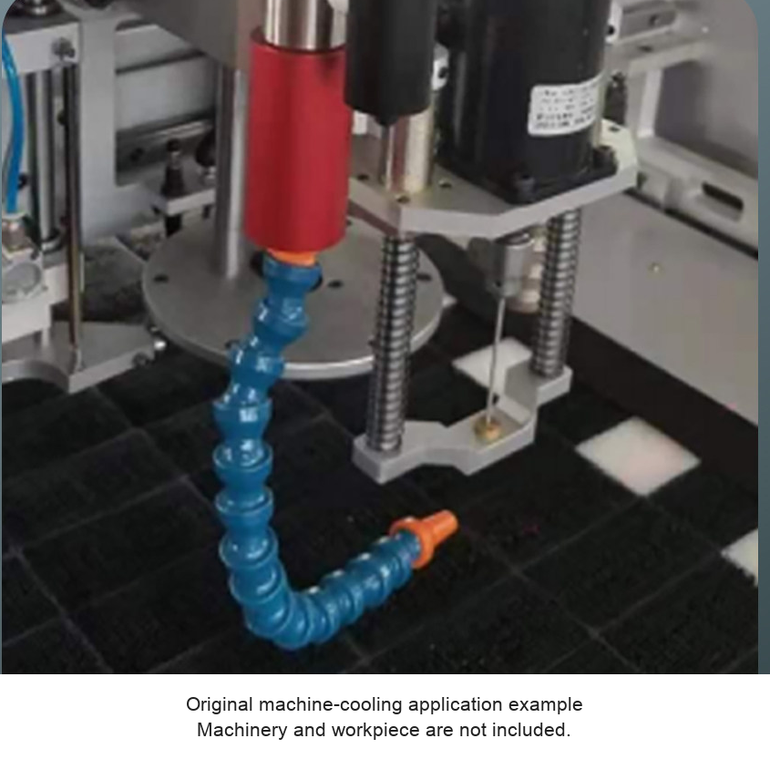
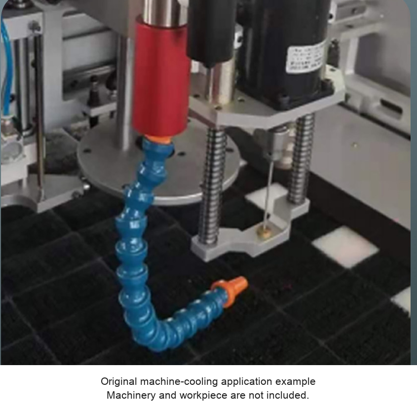
| Dry cutting / CNC machining | Aim the cold-air hose at the intended tool or work area. | Check the machining process, available clearance, air delivery and chip path. |
| Milling and localized tool cooling | Position and secure the hose for the working location. | Verify the actual cooling result and prevent contact with moving machinery. |
| Textile / cutting equipment | Use a directed stream where the equipment process permits. | Confirm material compatibility, dust handling and the machine instructions. |
| Loose-debris blow-off | Direct air away from the workpiece and sensitive components. | Provide suitable debris containment and control the supply. |
Supplier Reference Values
| Family | Air-volume entry m3 | Cooling Btu/hr | Noise dBA |
|---|---|---|---|
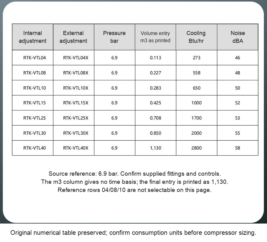
| RTK-VTL15 / 15X | 0.425 | 1000 | 52 |
| RTK-VTL25 / 25X | 0.708 | 1700 | 53 |
| RTK-VTL30 / 30X | 0.850 | 2000 | 55 |
| RTK-VTL40 / 40X | 1,130 (as printed) | 2800 | 58 |
The source reference pressure is 6.9 bar (0.69 MPa, approximately 100 psi). Its air-consumption column is labelled only m3, without a time basis, and the VTL40 row is printed as 1,130. These entries are retained without converting them into a confirmed compressor-flow requirement. Ask for verified consumption units before sizing the air supply. Cooling and noise figures are supplier references with incomplete test conditions.
The supplied material gives differing temperature-related claims and does not establish one rated outlet temperature or temperature drop for every setup. Actual cold-air temperature depends on inlet conditions, adjustment, flow, outlet arrangement and the process. No fixed outlet temperature is promised here.
Mounting, Controls and Materials
The source describes aluminum-alloy, stainless-steel and plastic components without assigning a certified grade to each part. The magnetic base must attach to a suitable ferromagnetic surface and hold securely for the intended operation. Do not assume it grips every metal, curved surface or nonmetallic housing. Check the actual base and mounting before use.
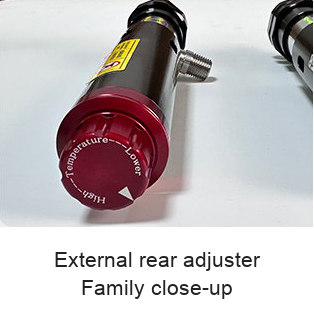
The pictured valve controls air supply through the base. Rear temperature/flow adjustment differs by model: the source shows a hand-operated external adjuster and an internal valve behind a threaded plug. Confirm the supplied control instructions. Isolate and depressurize before opening a rear plug or changing an internal part.
Setup and Process Check
- Select the model and adjustment style for the required process and air supply.
- Confirm inlet fitting, hose/nozzle contents, pressure limits and compressor flow units with the supplied unit.
- Provide a suitable controlled, clean and dry compressed-air supply. Secure the gun and keep both exhaust paths clear.
- Position the flexible hose without contact with moving tools, workpieces or guarding.
- Begin at a controlled setting. Observe the actual air temperature, coverage and process result before production use.
- Use the specified adjustment method, and isolate/depressurize before opening controls or replacing fittings and hoses.
Included-Item Check
One selected cooling-gun model/configuration. The source depicts a magnetic base, flow valve and a single flexible outlet. Confirm the exact supplied fittings, hose and nozzle before ordering. Multiple accessory hoses, compressor, filter/regulator, machinery, cutting tools and workpieces shown are not specified as included together in one price. No verified overall gun length or inlet thread is established for these eight source rows, so dimensions are not inferred from photo scale.
For a selection check, send model, cooling task, inlet pressure and confirmed available airflow, space/mounting arrangement and the required nozzle pattern to boltte@boltte.com.
Original Product, Drawing and Application Images
Clear source family photos, numerical table, vortex diagram, actual adjustment close-ups, original rear-valve section, nozzle examples and machining applications are retained below with English captions. Product geometry is preserved.




Modelo / configuración / SKU
| Modelo / configuración | SKU |
|---|---|
| RTK-VTL15 - Internal adjustment | 6245136071521 |
| RTK-VTL25 - Internal adjustment | 6245136071520 |
| RTK-VTL30 - Internal adjustment | 4978807285832 |
| RTK-VTL40 - Internal adjustment | 4978807285833 |
| RTK-VTL15X - External adjustment | 6245136071522 |
| RTK-VTL25X - External adjustment | 6245136071523 |
| RTK-VTL30X - External adjustment | 6245136071524 |
| RTK-VTL40X - External adjustment | 6245136071525 |