





RTK-VTL04 / 08 / 10 Small Vortex Cold Air Guns
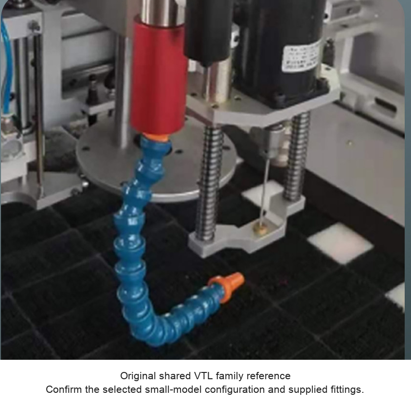
These small compressed-air cooling guns provide a positionable cold stream for localized cooling and blow-off. A segmented hose directs the outlet, and the source photographs show a magnetic mounting base and an air valve. The gun requires an external compressed-air supply. Select internal adjustment or the X external-adjustment version.
Select a Small-Gun Configuration
| Model | Adjustment | Original USD | Sale USD |
|---|---|---|---|
| RTK-VTL04 | Internal | 850 | 680.00 |
| RTK-VTL04X | External | 980 | 784.00 |
| RTK-VTL08 | Internal | 850 | 680.00 |
| RTK-VTL08X | External | 980 | 784.00 |
| RTK-VTL10 | Internal | 850 | 680.00 |
| RTK-VTL10X | External | 980 | 784.00 |
The source comparison table identifies X as external adjustment in this VTL gun family. This is different from suffix meanings used by other tube families. The priced small-model photographs show a single flexible outlet and a shared family photograph rather than independently scaled photos for each capacity. Confirm the exact supplied unit and connections. Medium VTL15/25/30/40 configurations are listed separately and are not duplicated on this page.
How the Cooling Gun Works
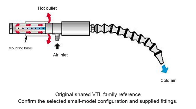
Compressed air enters the vortex body and separates into cold and hot streams. The cold stream travels through the positionable hose, while the hot stream exits separately. The gun itself is described as needing no electrical supply or refrigerant charge; the compressor and air treatment require their own installation. Maintain a clear exhaust path and avoid contact with hot surfaces.
Typical Applications
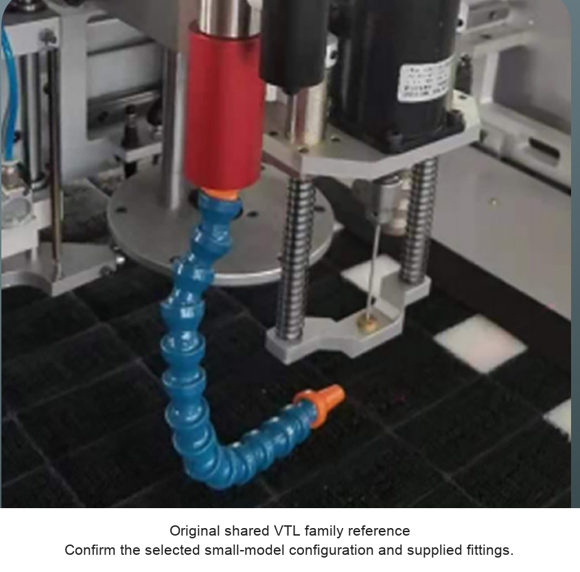
The original photos show dry cutting / CNC machining, milling-cutter cooling, textile/cutting equipment and a machine-cooling arrangement. Use these as process examples, not as a guarantee that one gun suits every operation. Check available space, required cooling, nozzle direction, chip/debris path, air quality and guarding before use. Machine tools, workpieces and other installed equipment are not included.
Supplier Reference Entries
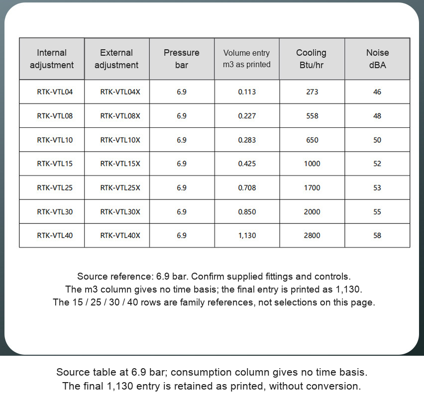
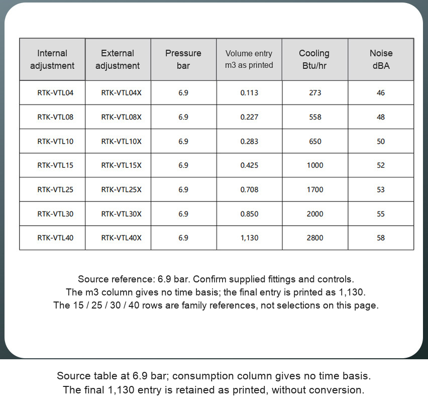
| Models | Reference pressure | Volume entry m3 as printed | Cooling Btu/hr | Noise dBA |
|---|---|---|---|---|
| VTL04 / 04X | 6.9 bar | 0.113 | 273 | 46 |
| VTL08 / 08X | 6.9 bar | 0.227 | 558 | 48 |
| VTL10 / 10X | 6.9 bar | 0.283 | 650 | 50 |
6.9 bar equals 0.69 MPa, approximately 100 psi. The original table labels consumption only m3 without a time basis. These numbers are retained as printed and are not converted into a verified compressor-flow specification. Confirm flow units, pressure limits, fitting/thread and rated conditions before sizing the air system. The table below also includes medium-family rows as references; only the six small options above are offered here.
Temperature-related marketing claims differ across the supplied material. No fixed outlet temperature or temperature drop is promised. Actual results depend on inlet temperature and pressure, delivered airflow, adjustment, outlet pattern and process conditions. Overall dimensions are not established by a matched drawing for these six SKU rows; model numbers and photograph scale are not treated as dimensions.
Controls, Mounting and Materials
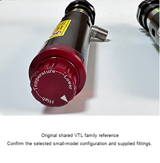
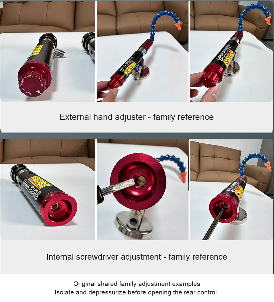
The normal version uses internal rear adjustment; X uses an external rear adjuster according to the supplied comparison table and small SKU captions. Shared family close-ups show the two control methods. Follow instructions for the actual supplied unit. Isolate and depressurize before removing a threaded plug or opening an internal adjuster.
The source describes aluminum-alloy, stainless-steel and plastic components without certifying the grade of each part. The magnetic base requires a suitable ferromagnetic mounting surface and a secure hold; not all metal surfaces can be used. The base-mounted valve regulates the supply. Confirm the hose/nozzle and inlet connection supplied with the chosen model.
Hose and Supply Scope
One selected small cooling-gun configuration is priced. Its source SKU photograph shows a base, valve and single segmented outlet hose. The common nozzle sheet identifies a single round nozzle as standard and single-flat, dual-flat and dual-round patterns as optional examples. Do not assume all pictured hoses or a dual-head bundle are included. Confirm any requested alternative before ordering. A compressor, air filter/regulator, machinery and workpieces are not specified as included.
Installation and First Use
- Confirm the selected model, adjustment style, supply pressure/flow and fitting details.
- Provide a suitable controlled, clean and dry compressed-air supply according to the unit instructions.
- Secure the base on a suitable surface and keep hot and cold outlet paths clear.
- Position the hose without interference with rotating tools, moving workpieces or guarding.
- Start under controlled conditions, measure the actual process result and adjust by the specified method.
- Isolate and depressurize before opening controls or changing fittings and hoses.
Selection Support
For a selection check, send the model, cooling task, inlet pressure and confirmed airflow units, mounting/space information and desired nozzle pattern to boltte@boltte.com.
Original Product, Drawing and Application Images
Clear original small-model photos, the numerical family table, vortex principle schematic, actual adjustment photographs and rear-valve section, base/valve close-ups, optional nozzle patterns and all supplied distinct application photographs appear below. Source geometry is retained.





Modelo / configuración / SKU
| Modelo / configuración | SKU |
|---|---|
| RTK-VTL04 - Internal adjustment | 5147338579764 |
| RTK-VTL04X - External adjustment | 5147338579757 |
| RTK-VTL08 - Internal adjustment | 5147338579752 |
| RTK-VTL08X - External adjustment | 5147338579758 |
| RTK-VTL10 - Internal adjustment | 5147338579751 |
| RTK-VTL10X - External adjustment | 5147338579759 |