


RTK-LAK Aluminum Compressed-Air Knives
An air knife delivers a narrow sheet of air along its outlet slot for surface blow-off, water removal, drying and localized cooling. The RTK-LAK family uses an aluminum-alloy body with threaded air connections and mounting features. An external compressed-air supply is required. Select the listed length/model, or confirm a custom specification before ordering.
Model, Length and Price Selection
| Model / selection | Source length / inch reference | Original USD | Sale USD |
|---|---|---|---|
| RTK-LAK30 | 30 mm / 1.181 in | 180 | 144.00 |
| RTK-LAK50 | 50 mm / 1.969 in | 280 | 224.00 |
| RTK-LAK80 | Confirm dimensions | 450 | 360.00 |
| RTK-LAK100 | 100 mm / 3.937 in | 520 | 416.00 |
| RTK-LAK150 | 150 mm / 5.906 in | 580 | 464.00 |
| RTK-LAK200 | 200 mm / 7.874 in | 620 | 496.00 |
| RTK-LAK250 | 250 mm / 9.843 in | 650 | 520.00 |
| RTK-LAK300 | 300 mm / 11.811 in | 680 | 544.00 |
| RTK-LAK350 | 350 mm / 13.780 in | 750 | 600.00 |
| RTK-LAK400 | 400 mm / 15.748 in | 780 | 624.00 |
| RTK-LAK450 | 450 mm / 17.717 in | 850 | 680.00 |
| RTK-LAK500 | 500 mm / 19.685 in | 900 | 720.00 |
| RTK-LAK550 | 550 mm / 21.654 in | 950 | 760.00 |
| RTK-LAK600 | 600 mm / 23.622 in | 980 | 784.00 |
| RTK-LAK650 | 650 mm / 25.591 in | 1050 | 840.00 |
| RTK-LAK700 | 700 mm / 27.559 in | 1100 | 880.00 |
| RTK-LAK750 | 750 mm / 29.528 in | 1260 | 1008.00 |
| RTK-LAK800 | 800 mm / 31.496 in | 1380 | 1104.00 |
| RTK-LAK850 | 850 mm / 33.465 in | 1460 | 1168.00 |
| RTK-LAK900 | 900 mm / 35.433 in | 1580 | 1264.00 |
| RTK-LAK950 | 950 mm / 37.402 in | 1670 | 1336.00 |
| Custom specification | Confirm dimensions | 1980 | 1584.00 |
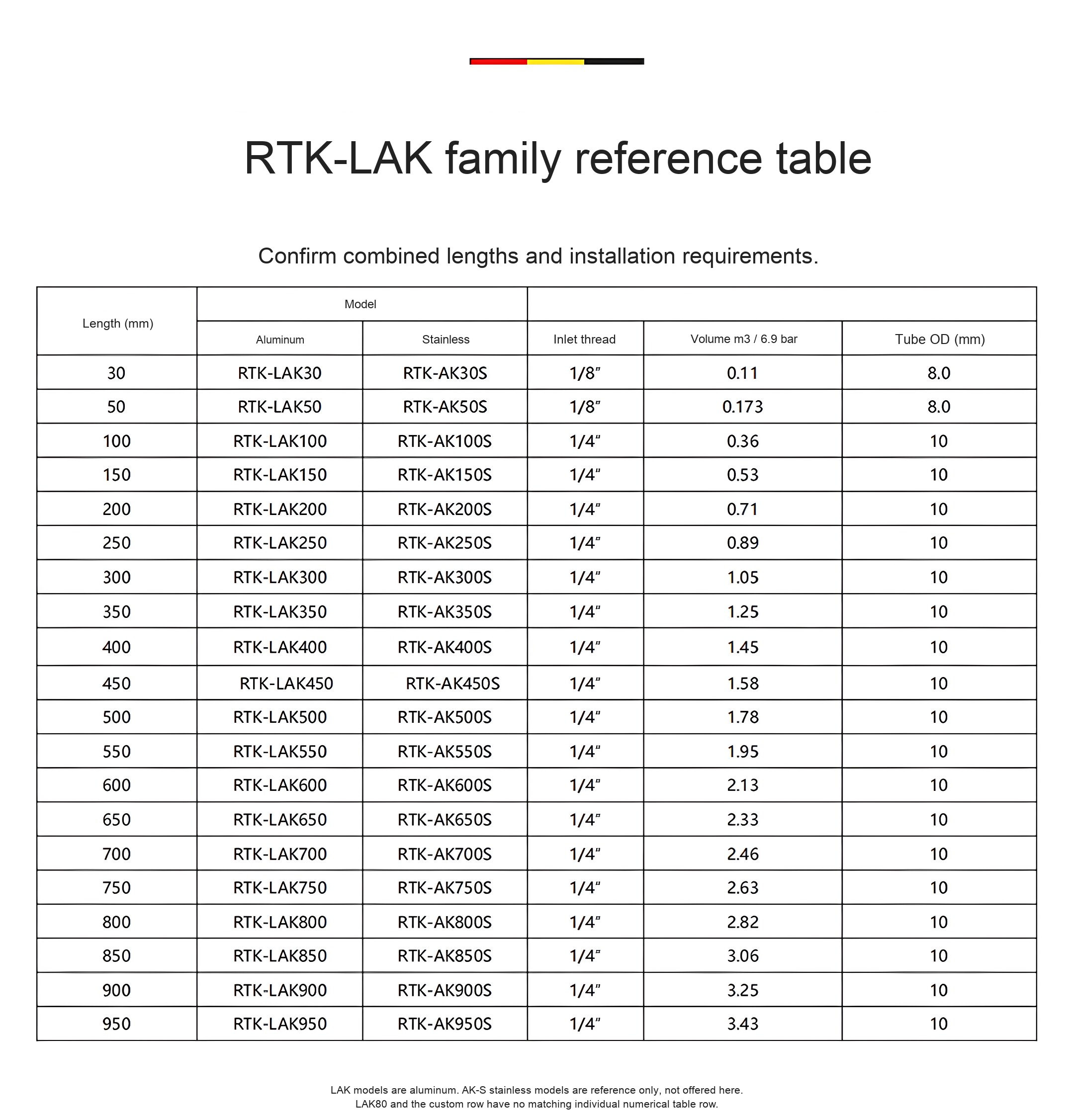
The supplier table explicitly matches the listed LAK model numbers to body length L in millimetres, except LAK80: that priced SKU has no matching separate table row. LAK80 dimensions, inlet and air-use data therefore need confirmation. The table is not a statement of overall length including fittings. Inches are calculated from 25.4 mm per inch.
The custom-specification option has a source-listed price but no finished dimensions or defined machining scope. Confirm an agreed drawing, slot gap, length, connection and supplied contents before ordering that option. No arbitrary custom size or lead time is promised. All selectable standard models here are the silver aluminum LAK family; the AK-S stainless references in the original table are not selectable on this page.
What the Air Knife Does
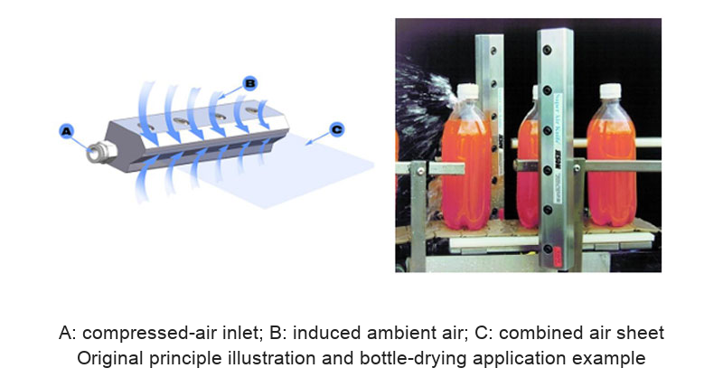
Compressed air enters the internal plenum and leaves through the narrow outlet slot. The emerging stream entrains surrounding air, producing a sheet directed along the working surface. Set the angle and distance to suit the item being processed. The original source illustration marks A as the compressed-air inlet, B as induced surrounding air and C as the combined discharge.
Applications and Setup Considerations
| Application | Purpose | What to confirm |
|---|---|---|
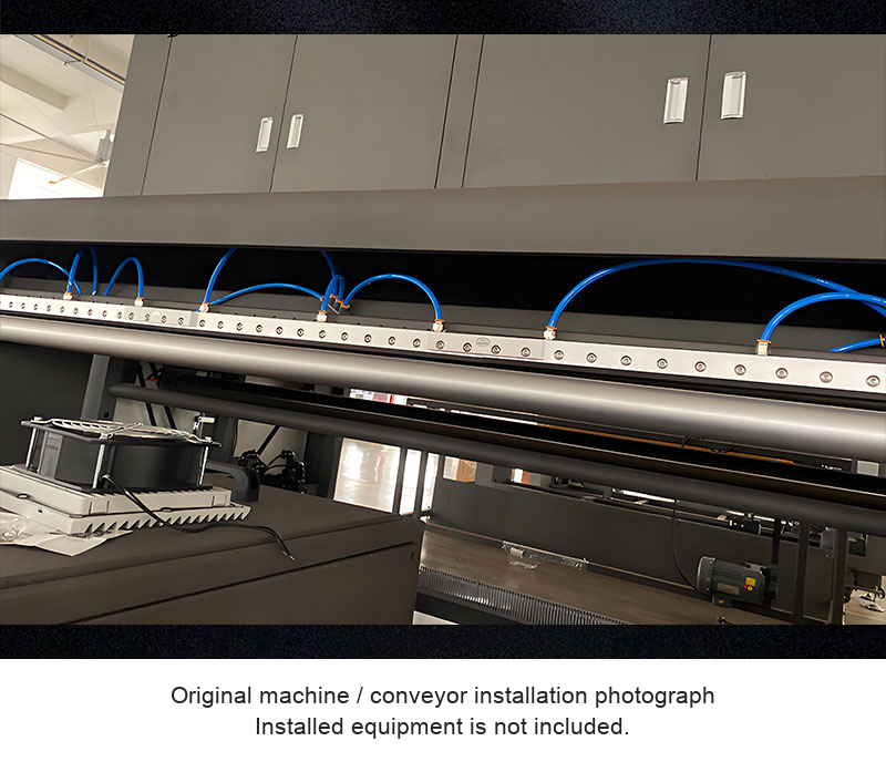
| Bottle / container drying | Blow residual surface water from containers moving past the knife. | Coverage, conveyor clearance, supply air quality and drainage. |
| Sheet / component blow-off | Remove loose dust or droplets where the process permits. | Surface compatibility, contamination control and debris containment. |
| Process drying / cooling | Direct an air sheet over a local working area. | Required process result, actual inlet pressure and delivered flow. |
| Longer working widths | The source describes arranging multiple knives to cover a longer width. | Mounting, alignment, gaps and supply distribution; a seamless result is not assumed. |
The source mentions static removal as a possible use, but it does not establish a built-in ionizer, electrical ionization system or verified static-decay performance. This page does not present the air knife as an ionizing static eliminator. Use an appropriate verified system where electrostatic control is required.
Source Air-Supply Reference
| Length L mm | Inlet size as printed | Volume entry m3 at 6.9 bar | Supply tube OD mm |
|---|---|---|---|
| 30 | 1/8 inch | 0.11 | 8.0 |
| 50 | 1/8 inch | 0.173 | 8.0 |
| 100 | 1/4 inch | 0.36 | 10 |
| 150 | 1/4 inch | 0.53 | 10 |
| 200 | 1/4 inch | 0.71 | 10 |
| 250 | 1/4 inch | 0.89 | 10 |
| 300 | 1/4 inch | 1.05 | 10 |
| 350 | 1/4 inch | 1.25 | 10 |
| 400 | 1/4 inch | 1.45 | 10 |
| 450 | 1/4 inch | 1.58 | 10 |
| 500 | 1/4 inch | 1.78 | 10 |
| 550 | 1/4 inch | 1.95 | 10 |
| 600 | 1/4 inch | 2.13 | 10 |
| 650 | 1/4 inch | 2.33 | 10 |
| 700 | 1/4 inch | 2.46 | 10 |
| 750 | 1/4 inch | 2.63 | 10 |
| 800 | 1/4 inch | 2.82 | 10 |
| 850 | 1/4 inch | 3.06 | 10 |
| 900 | 1/4 inch | 3.25 | 10 |
| 950 | 1/4 inch | 3.43 | 10 |
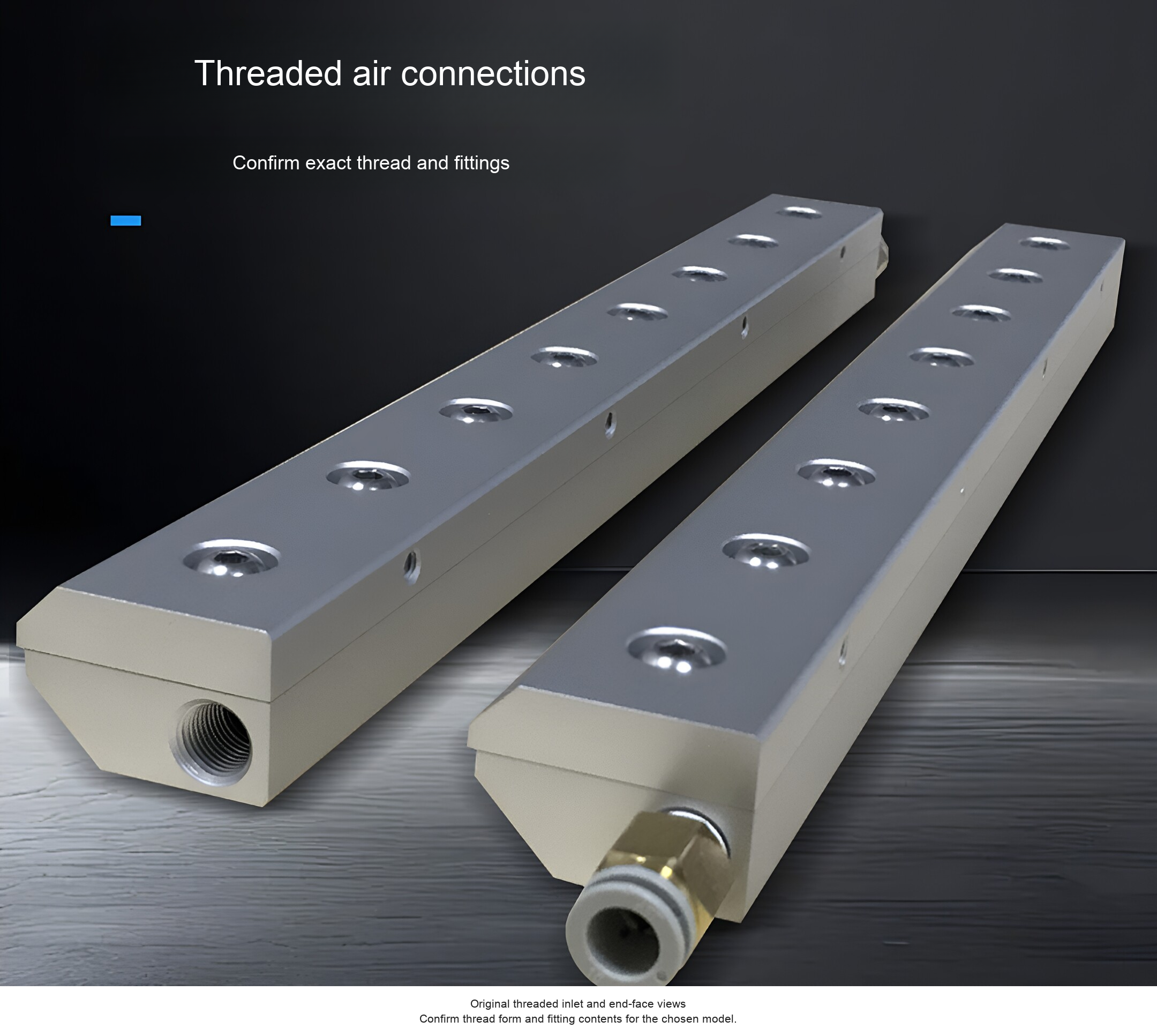
The source reference pressure is 6.9 bar (0.69 MPa, approximately 100 psi). The volume column is labelled m3 / 6.9 bar with no time basis. Values are kept as printed, without converting them into a confirmed flow rate or compressor requirement. Confirm actual consumption units and operating limits for the chosen length. The family drawing prints a PT1/4 connection with a 10 mm tube reference, while the 30/50 table rows show 1/8-inch connections and 8 mm tube OD. Confirm exact thread form, size and supplied fitting rather than assuming all models use one connection.
Mounting, Outlet Gap and Reference Drawing
The source attributes state M8 mounting threads and a standard outlet gap of 0.05 mm (approximately 0.00197 in). The product photo also describes custom gaps from 0.05 to 0.3 mm (approximately 0.00197 to 0.01181 in), subject to an agreed specification. Do not assume a different gap is included in a standard option.
The original family cross-section shows 44.50 mm (1.752 in), 37 mm (1.457 in), 32 mm (1.260 in), 13 mm (0.512 in) and 12 mm (0.472 in) spans. Another view marks 23 mm (0.906 in), 50 mm (1.969 in) and 25 mm (0.984 in) spans and M8 mounting threads. These are reference spans, not a universal hole schedule for every length. Obtain the selected model drawing before drilling the installation or ordering a custom version.
Installation and Operation
- Select the required effective coverage and confirm body length, end connections and mounting drawing.
- Provide suitable controlled compressed air and air treatment for the process and unit instructions. Confirm the allowed pressure and delivered flow.
- Mount securely with the intended fasteners, supporting the body without distorting the slot. Confirm torque and mounting details for the actual unit.
- Aim the outlet toward the working area with adequate clearance from machinery, products and guarding.
- Start with a controlled setting and measure the actual drying, blow-off or cooling result. Adjust angle, distance and supply as required.
- Isolate and depressurize before changing fittings or cleaning/opening the body. Avoid damaging the narrow outlet slot.
Included Items and Custom Requirements
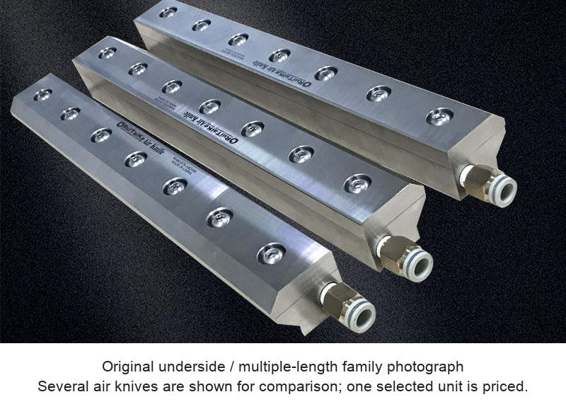
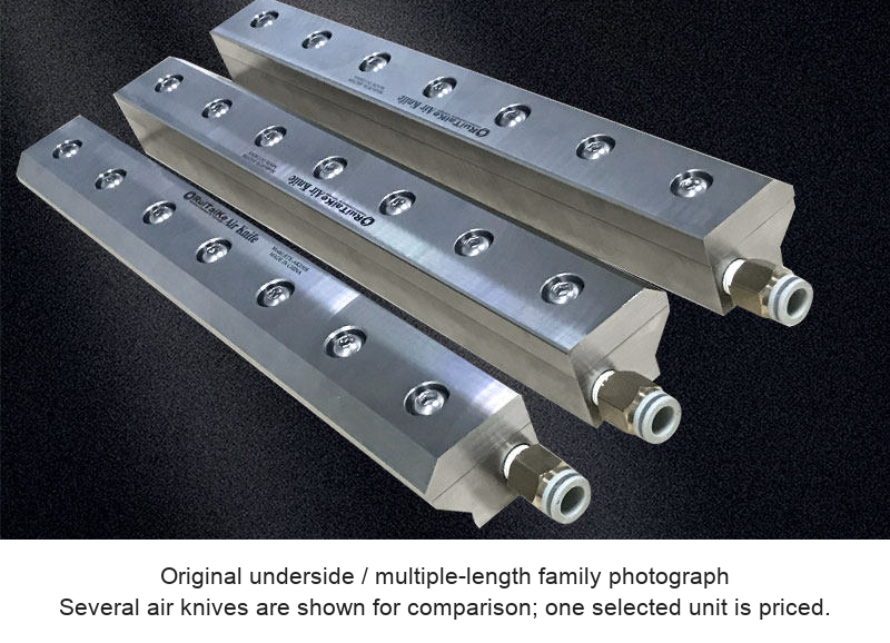
One selected aluminum air knife or one agreed custom specification is priced. Shared photographs show multiple lengths and sample fittings for comparison; they do not mean every pictured air knife is included in one order. Confirm end fittings and supplied mounting hardware. A compressor, regulator/filter, conveyor, bottles, machinery and workpieces are not specified as included.
For a selection check, send model or target coverage, application, available inlet pressure and confirmed airflow units, fitting/thread requirements, mounting space and any custom slot/drawing requirements to boltte@boltte.com.
Original Product, Drawing and Application Images
Original aluminum-body and threaded-port views, underside photos, M8/slot references, high-resolution numerical table, complete joined family drawing, working-principle illustration and actual bottle/conveyor applications are retained below. Product geometry and original dimension lines are preserved.