KC 45-Steel Roller-Chain Shaft Couplings
Fifty-six selectable configurations combine KC model size, custom bore range, black-oxide treatment and housing selection. Each option identifies whether a housing is included. The displayed bore range is machining scope, not a supplied fixed bore pair.
Custom Ordering
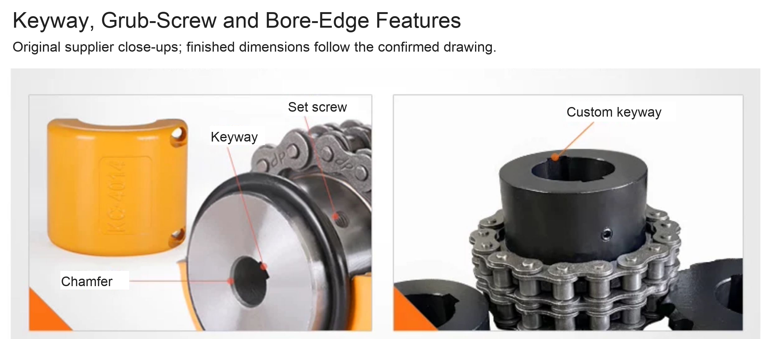
Provide both finished shaft bores, fits, keyways, hub engagement lengths and the drawing or sample requirements in Order requirements or contact BOLTTE. Confirm the manufacturing specification before production. Requirements outside the selected configuration need separate confirmation before ordering. Custom processing time is confirmed separately from shipping transit estimates.
Construction and Configuration
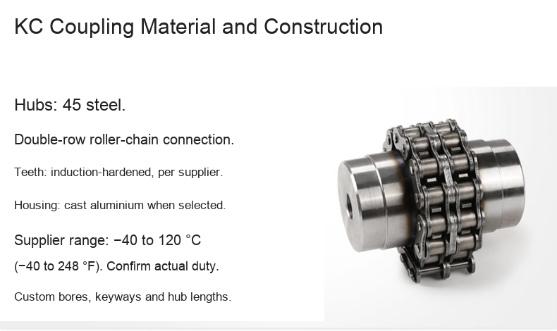
- 45-steel coupling hubs connected by a double-row roller chain, as identified by the supplier.
- Black-oxide-treated and non-black-oxide options retain their separate prices.
- Cast-aluminium housing only with options marked With Housing. It is not included with Without Housing configurations.
- Supplier-described high-frequency induction hardening. No independently verified hardness certificate is supplied.
- Supplier-listed temperature range −40 to 120 °C (−40 to 248 °F). Confirm suitability for the actual duty and supplied assembly.
Model and Bore Selection
Millimetres remain authoritative; inch equivalents are rounded to three decimals.
| Model | Custom bore range (mm / in) | D (mm / in) | Hub L (mm / in) |
|---|---|---|---|
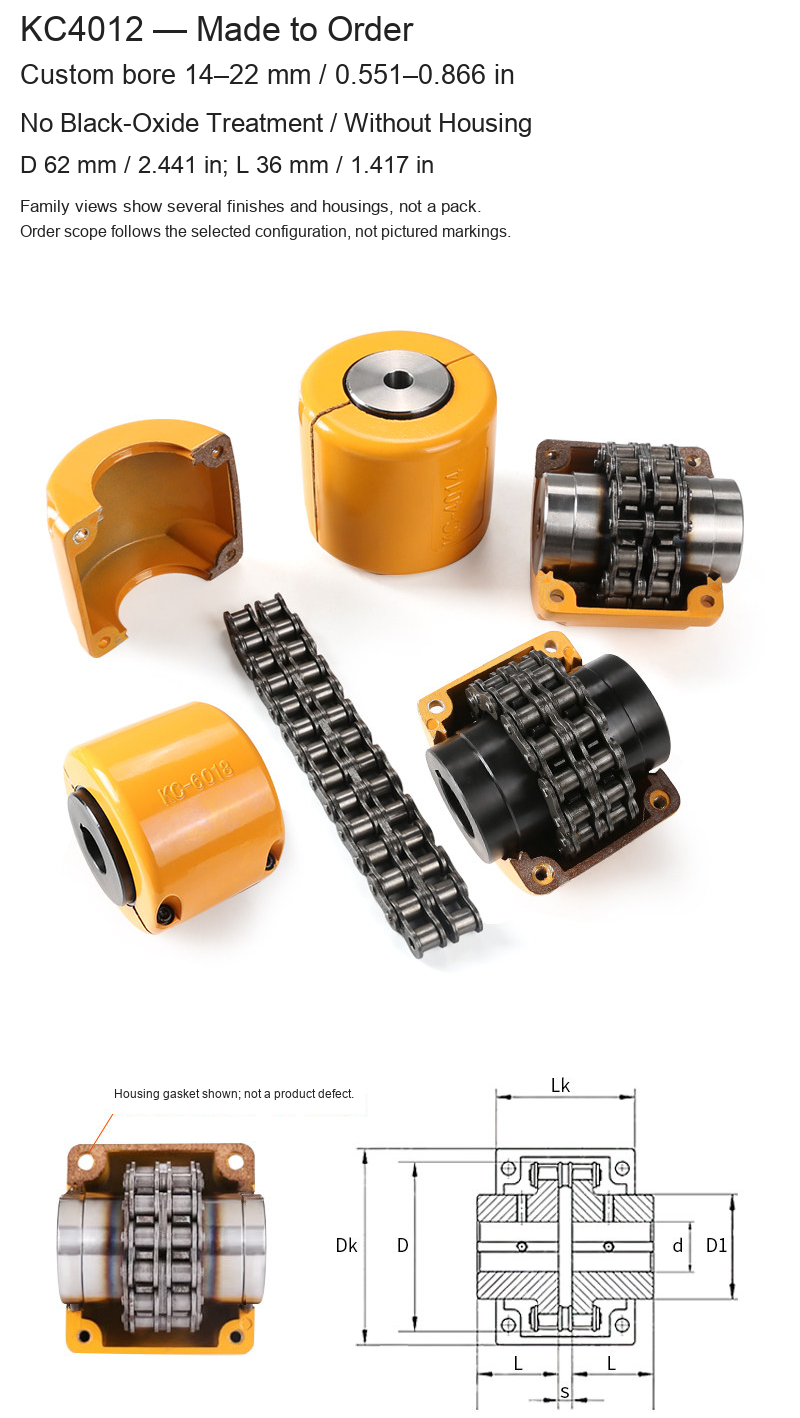
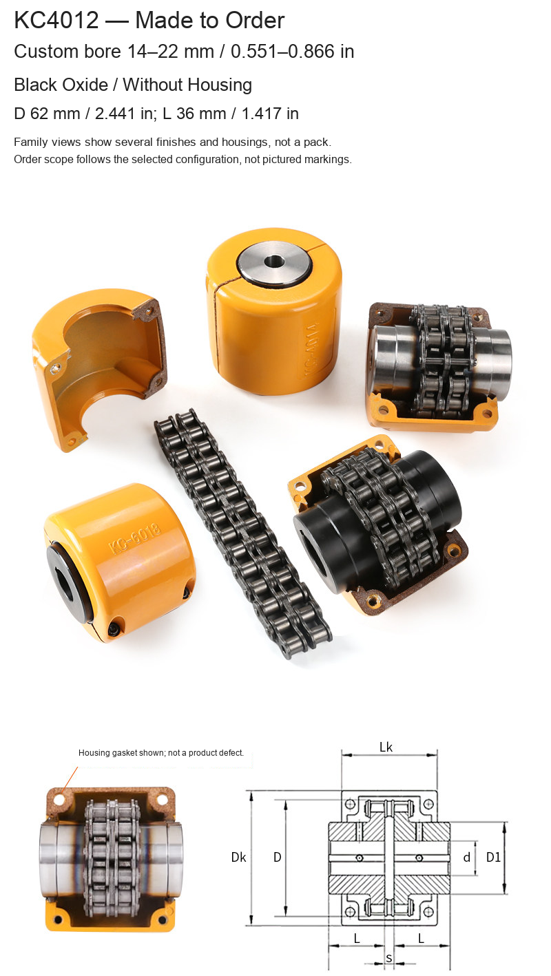
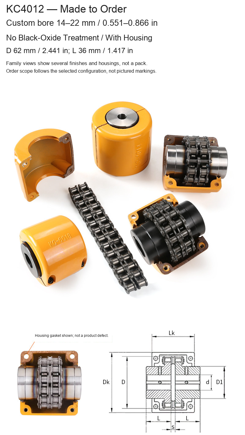
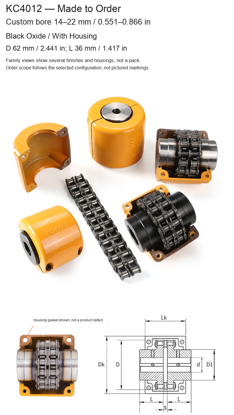
| KC4012 | 14–22 / 0.551–0.866 | 62 / 2.441 | 36 / 1.417 |
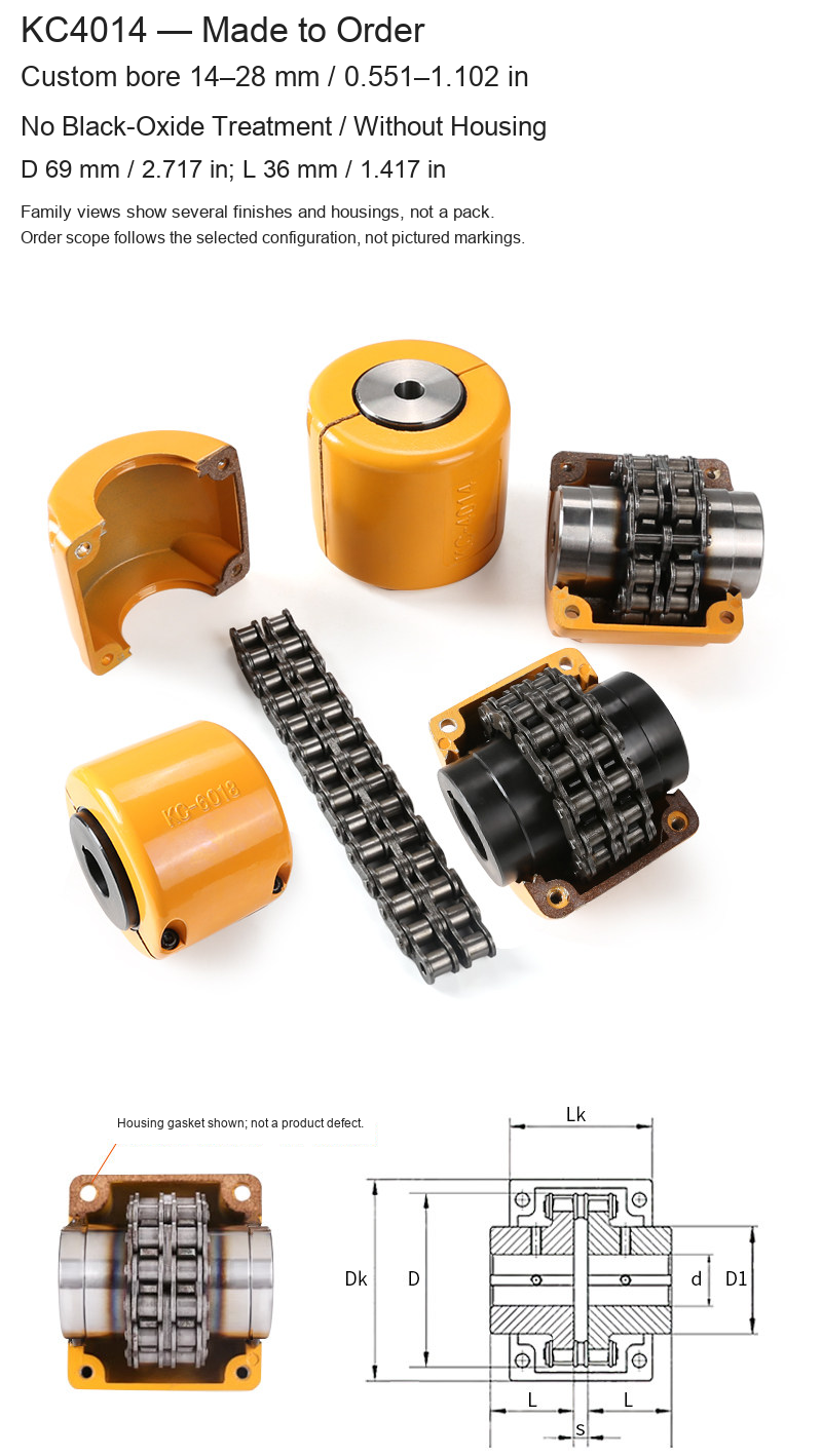
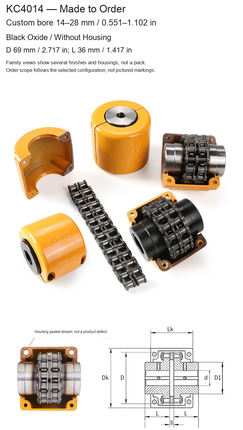
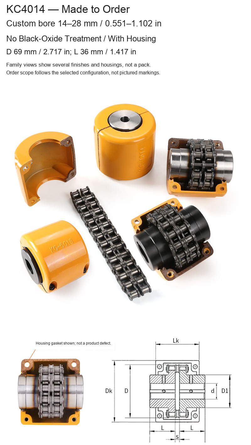
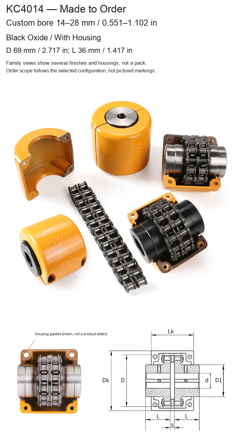
| KC4014 | 14–28 / 0.551–1.102 | 69 / 2.717 | 36 / 1.417 |
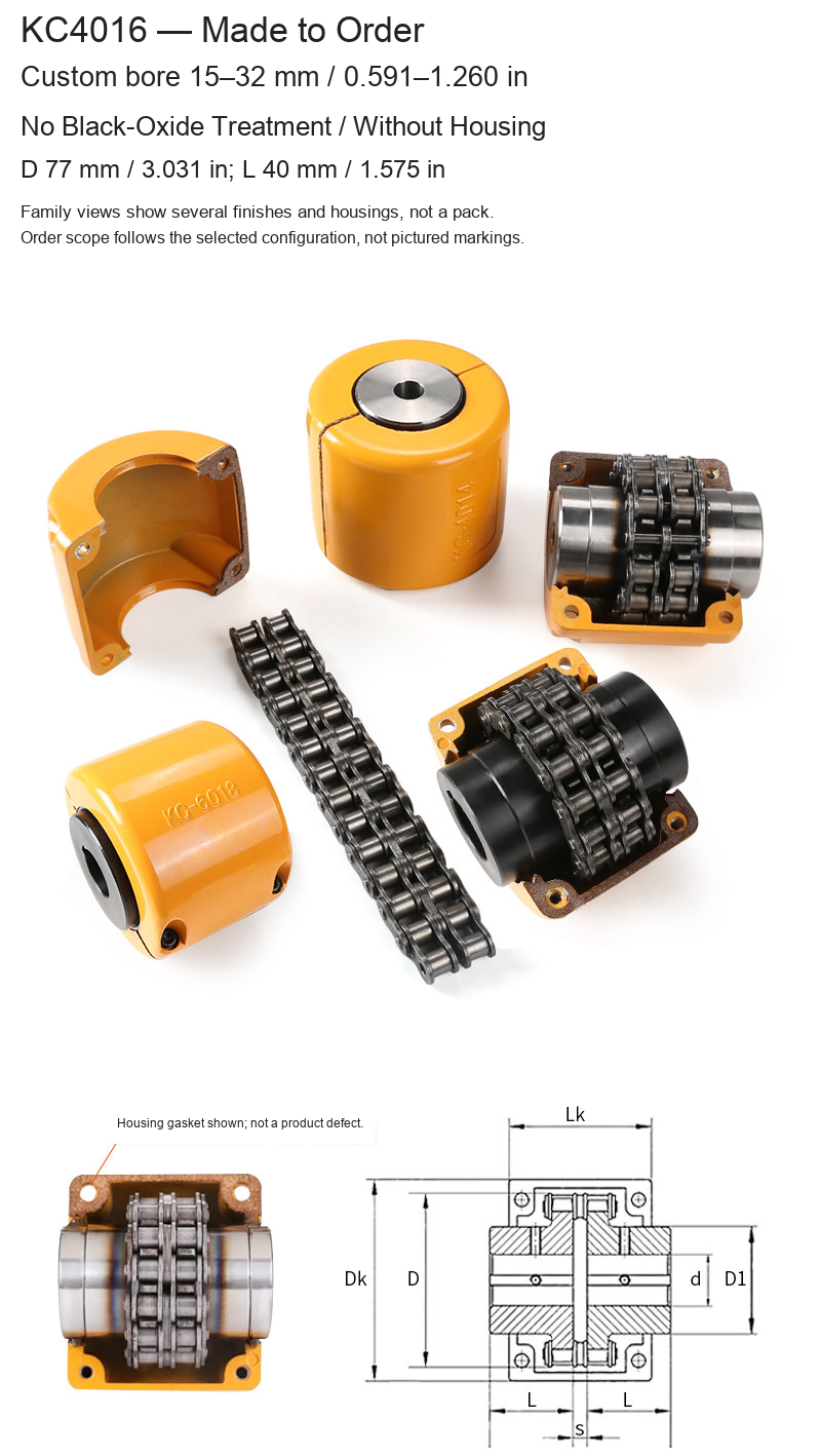
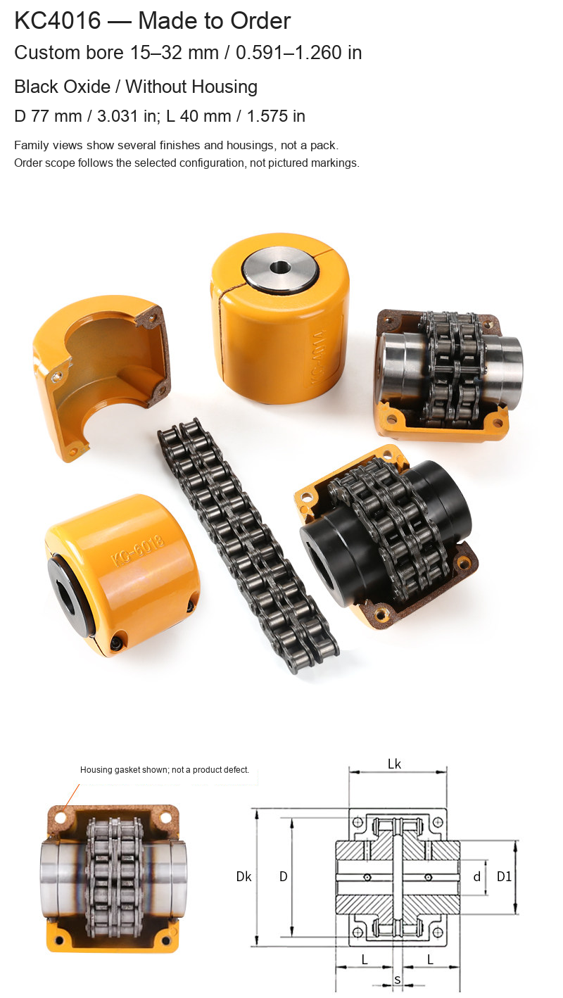
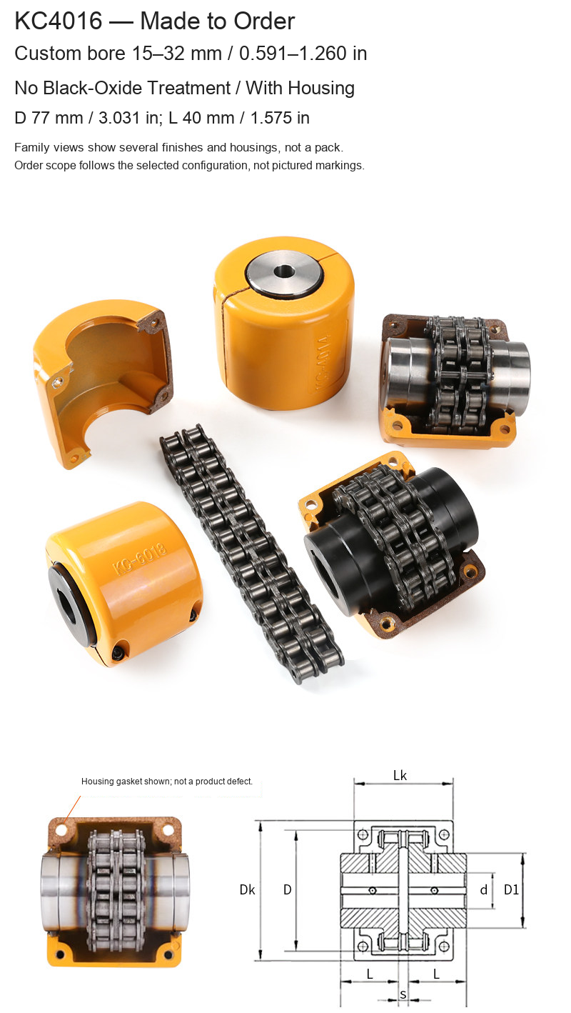
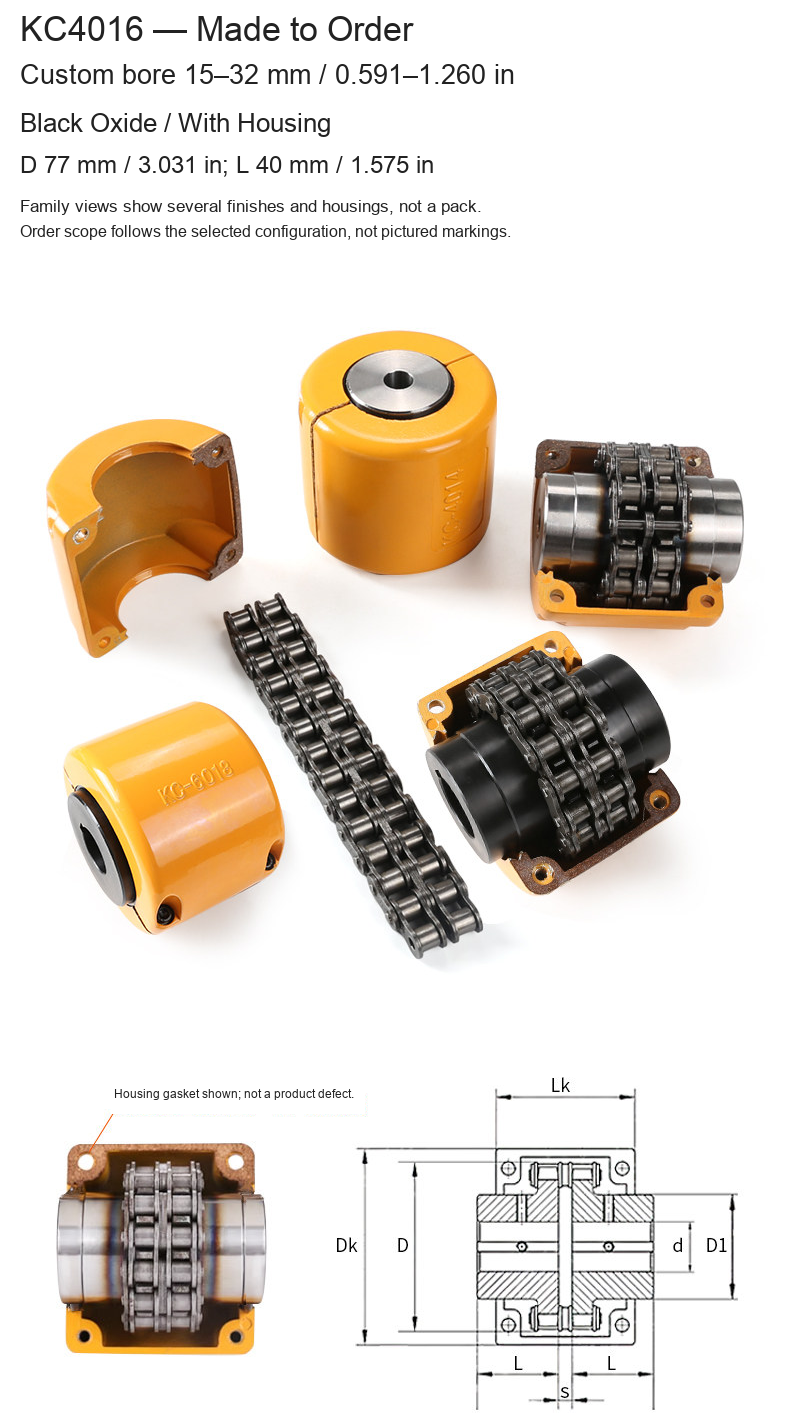
| KC4016 | 15–32 / 0.591–1.260 | 77 / 3.031 | 40 / 1.575 |
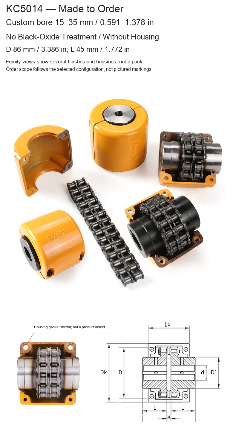
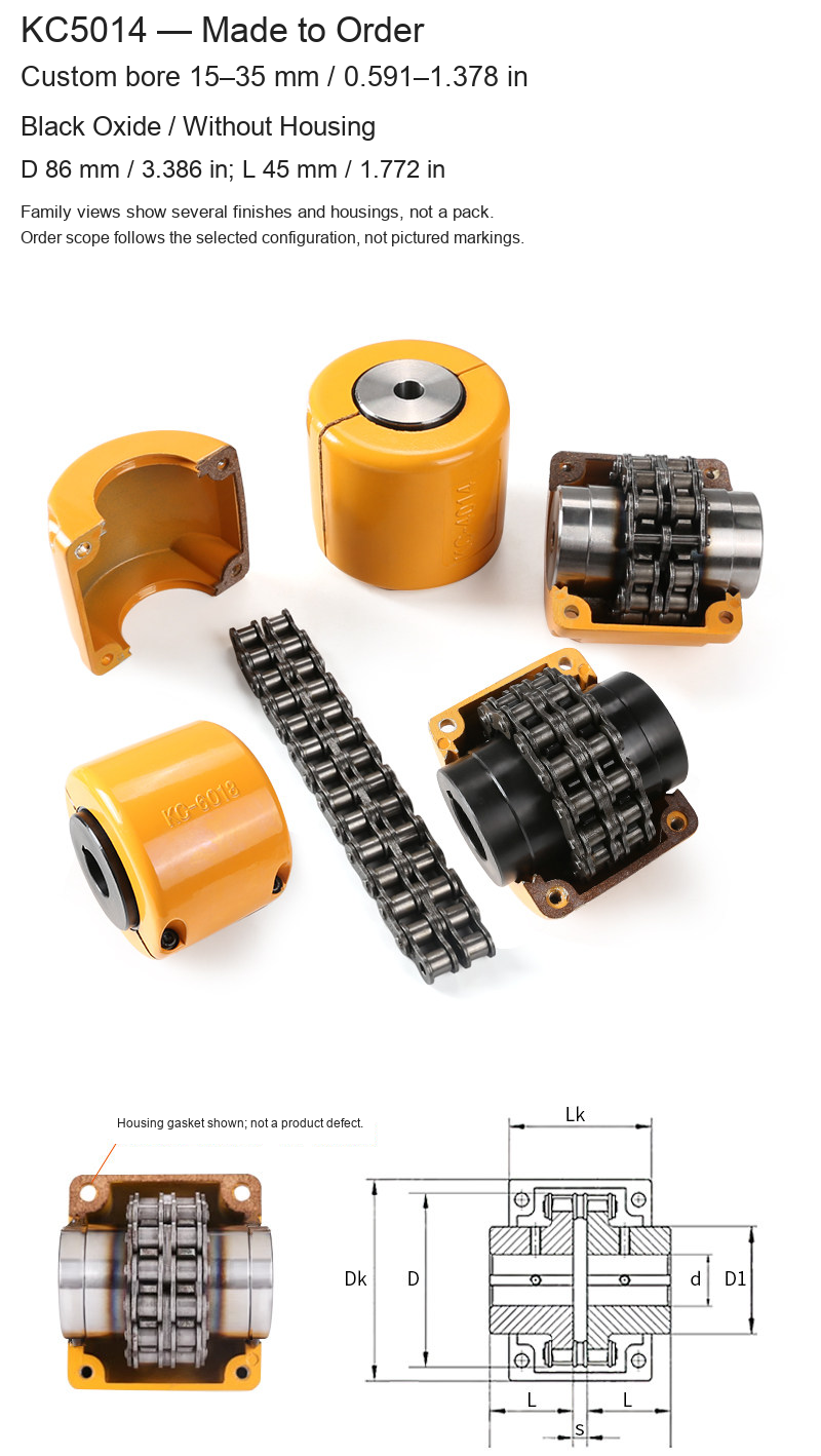
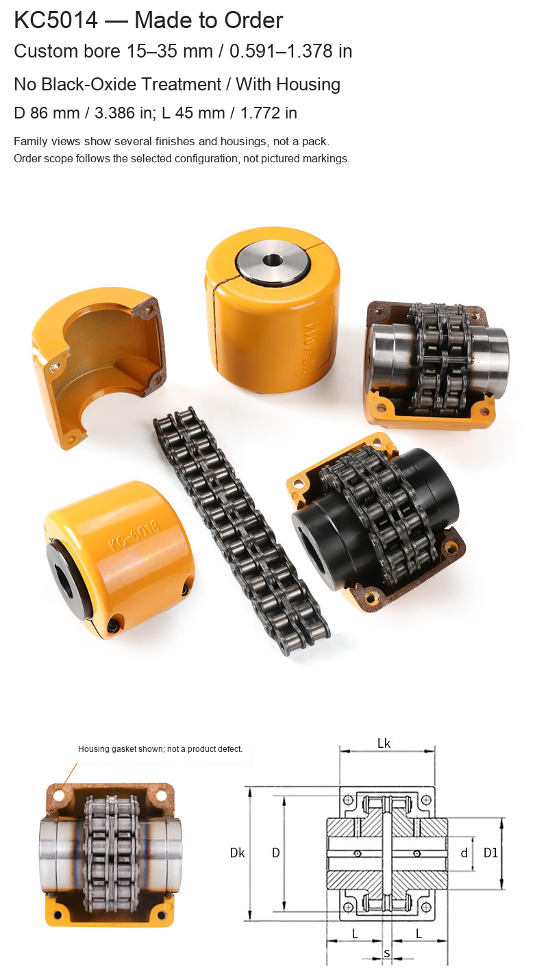
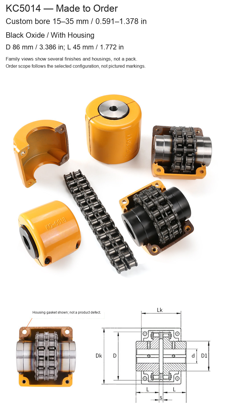
| KC5014 | 15–35 / 0.591–1.378 | 86 / 3.386 | 45 / 1.772 |
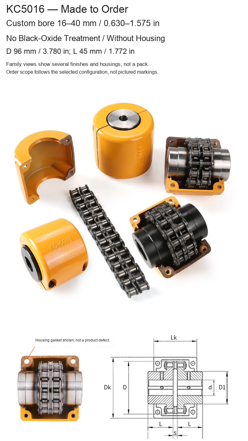
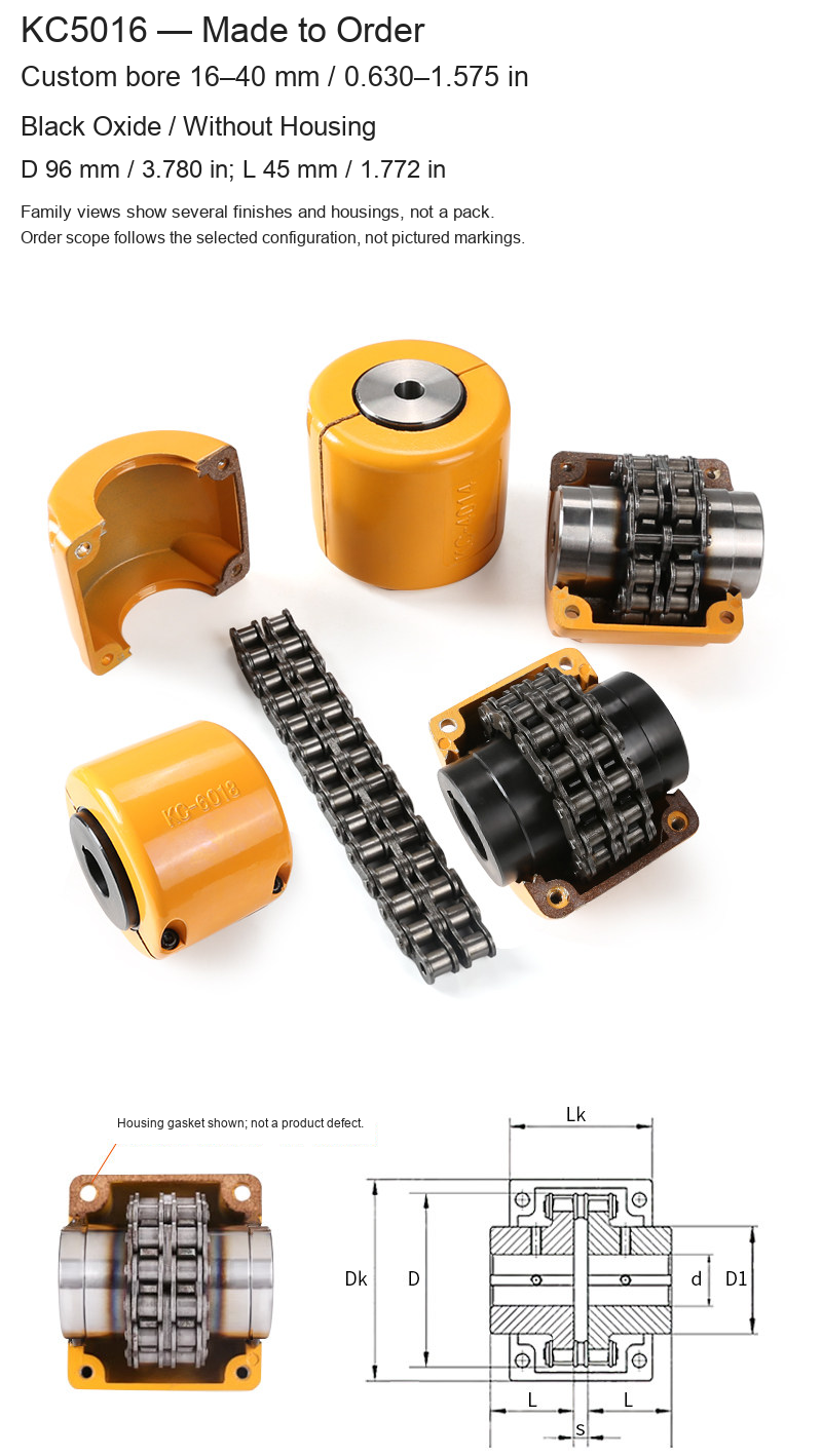
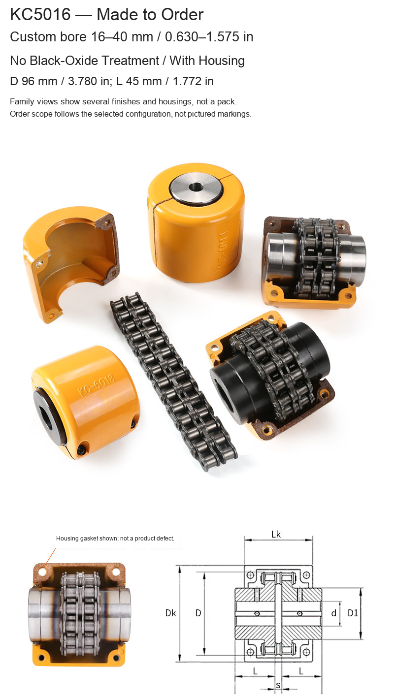
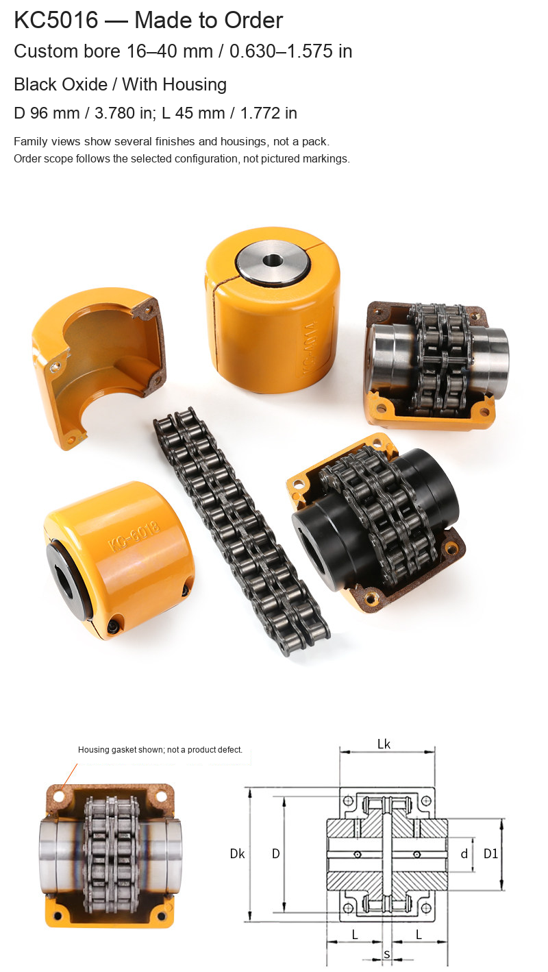
| KC5016 | 16–40 / 0.630–1.575 | 96 / 3.780 | 45 / 1.772 |
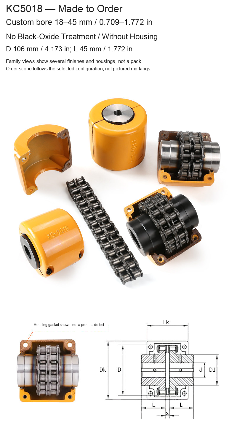
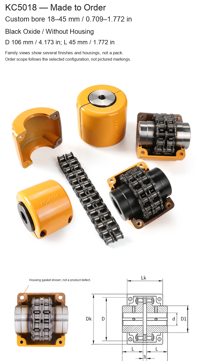
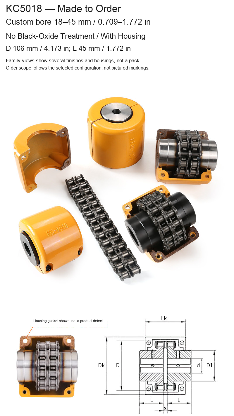
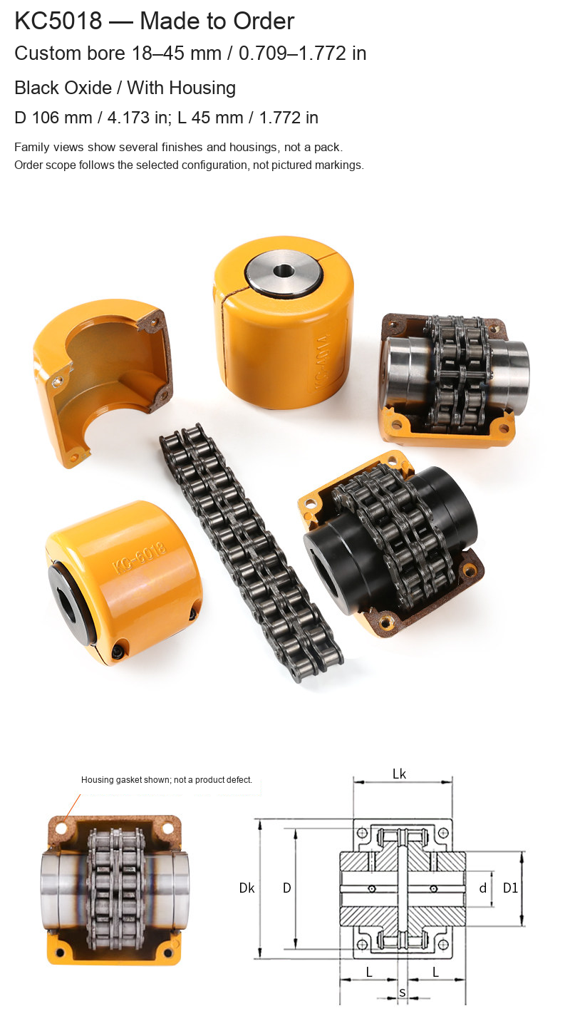
| KC5018 | 18–45 / 0.709–1.772 | 106 / 4.173 | 45 / 1.772 |
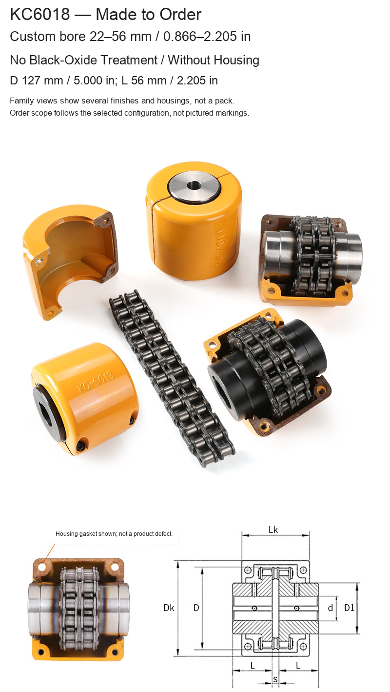
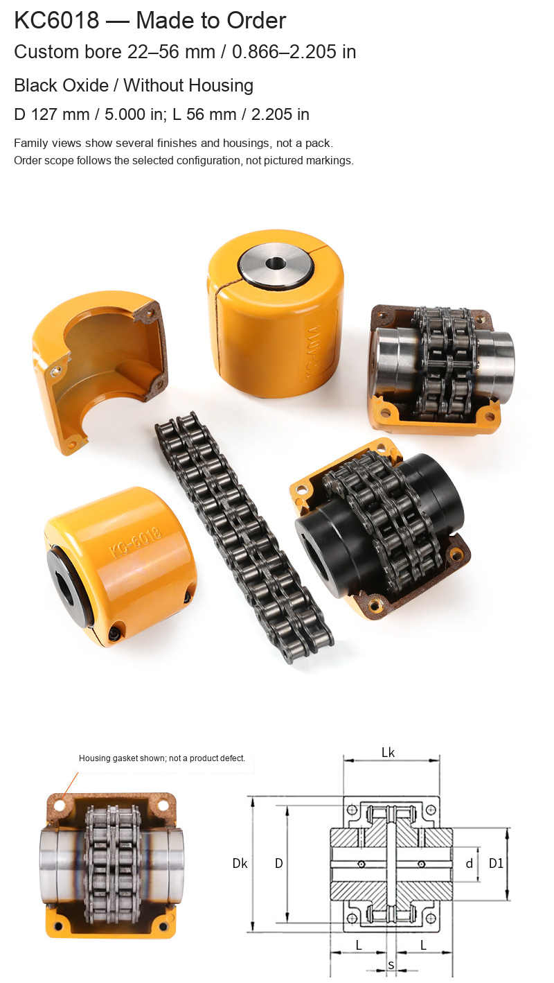
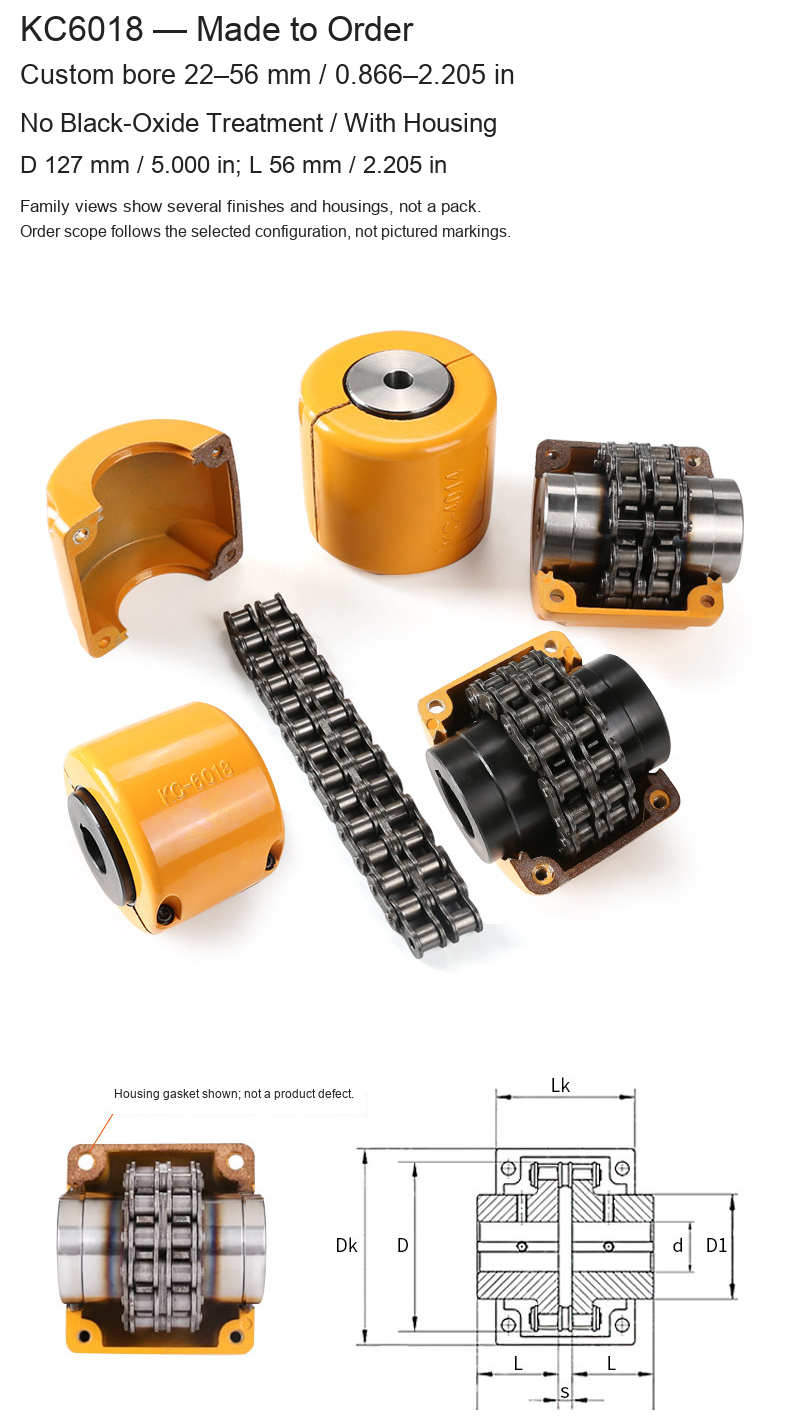
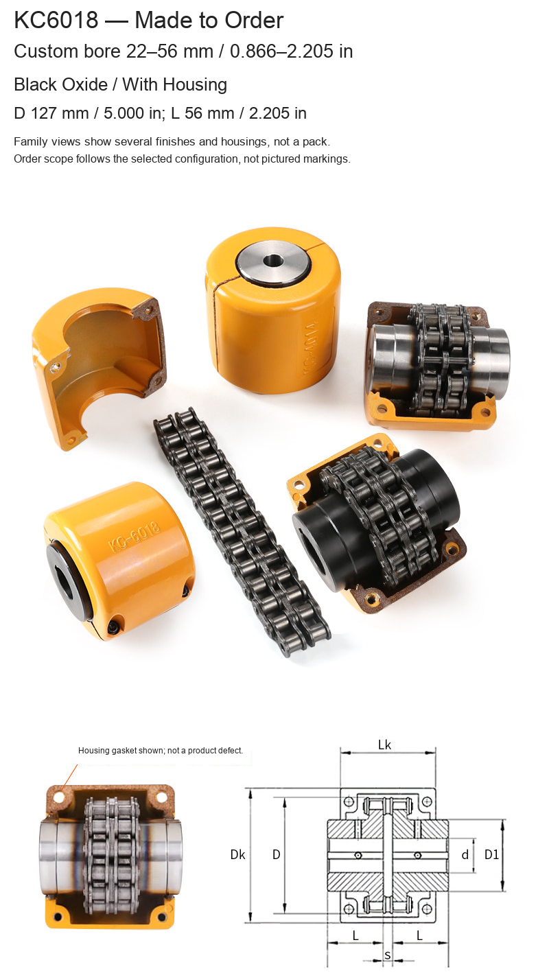
| KC6018 | 22–56 / 0.866–2.205 | 127 / 5.000 | 56 / 2.205 |
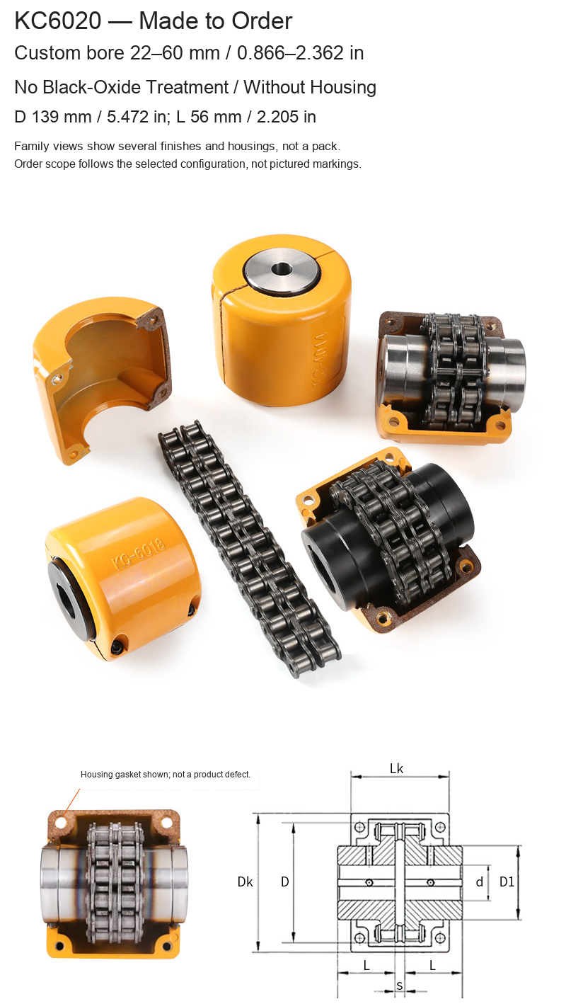
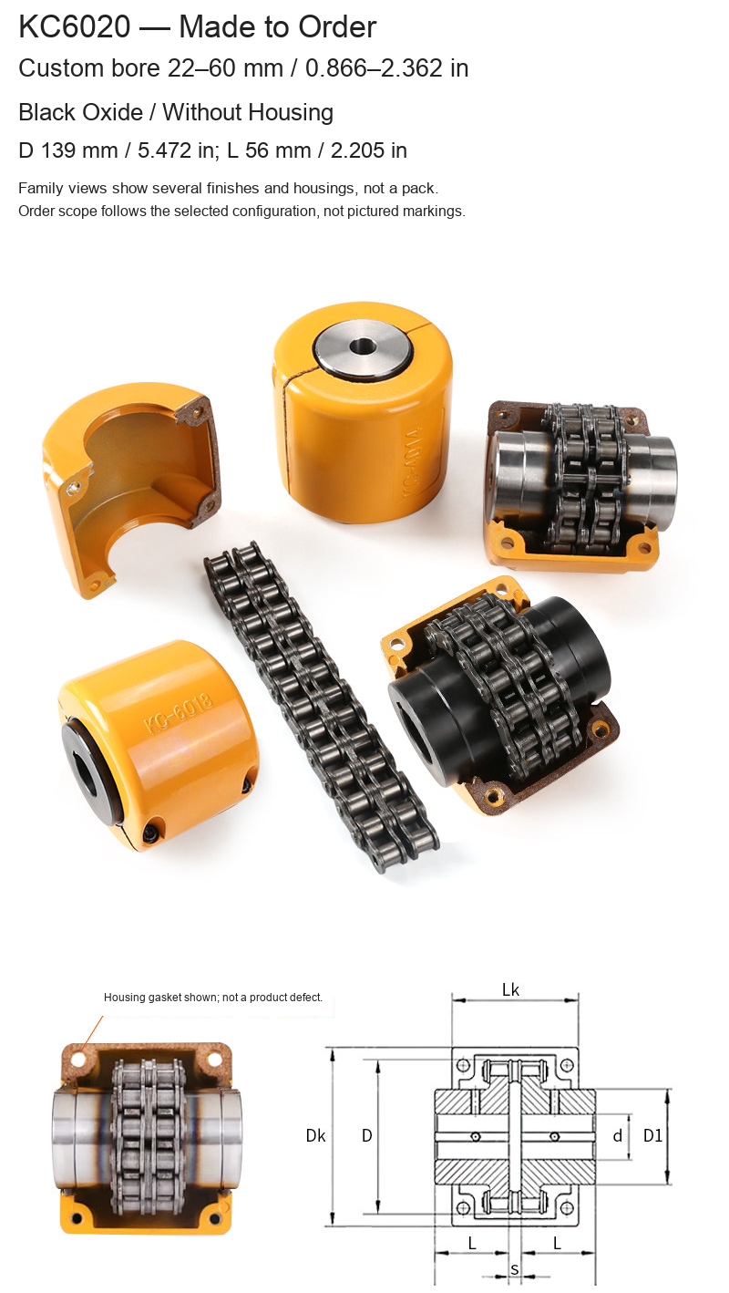
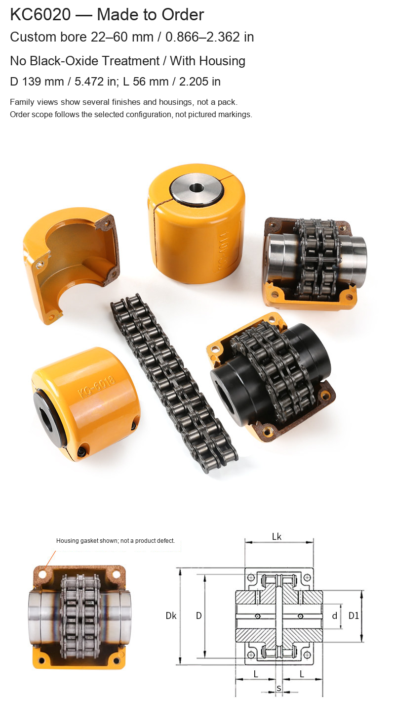
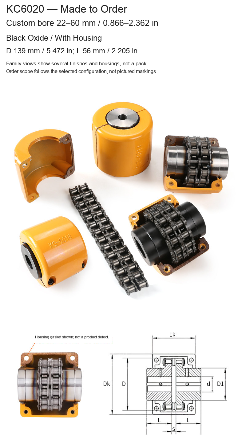
| KC6020 | 22–60 / 0.866–2.362 | 139 / 5.472 | 56 / 2.205 |
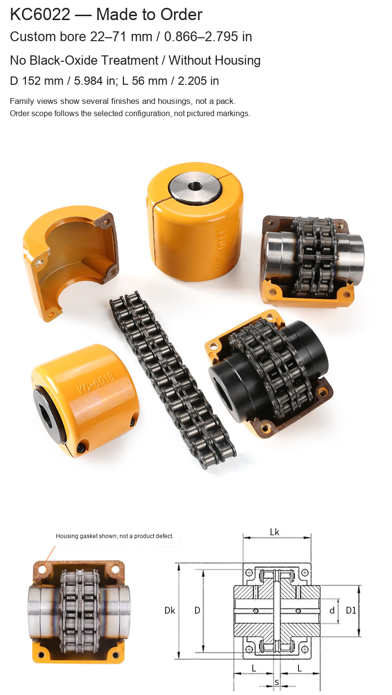
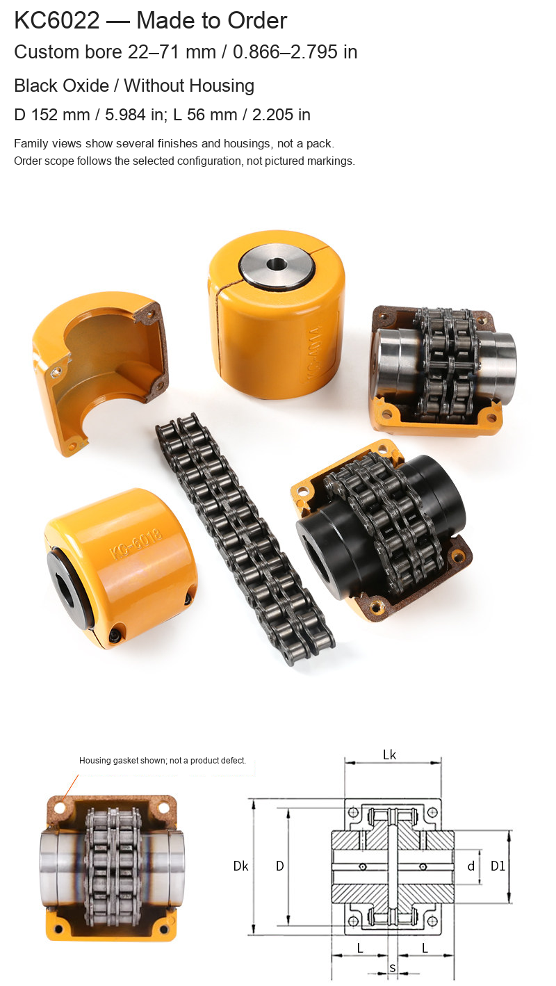
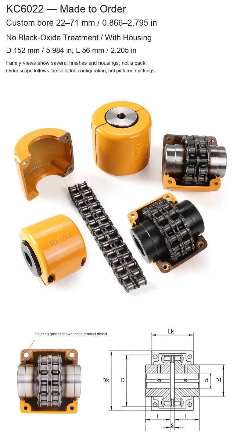
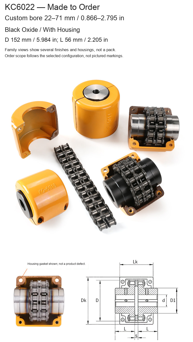
| KC6022 | 22–71 / 0.866–2.795 | 152 / 5.984 | 56 / 2.205 |
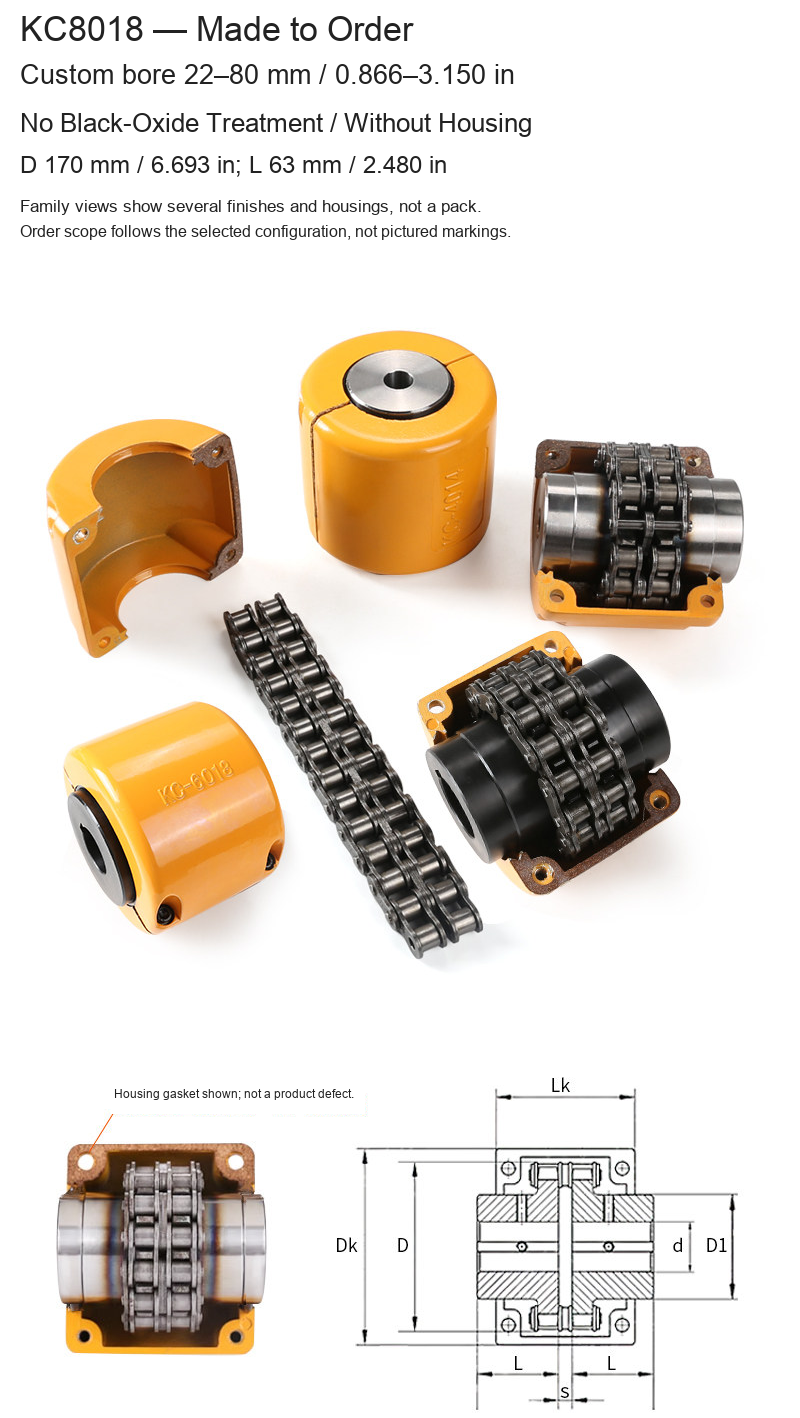
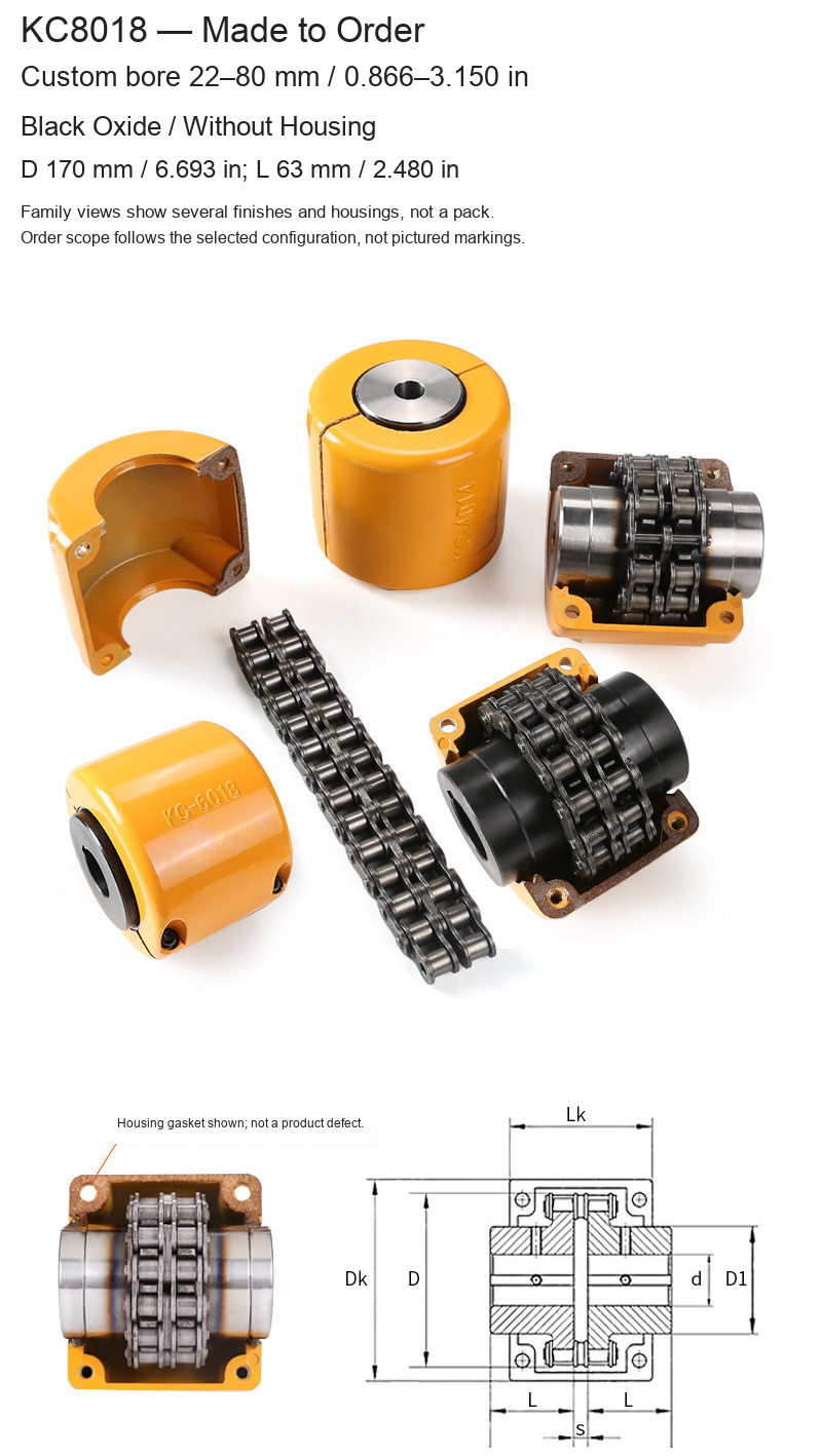
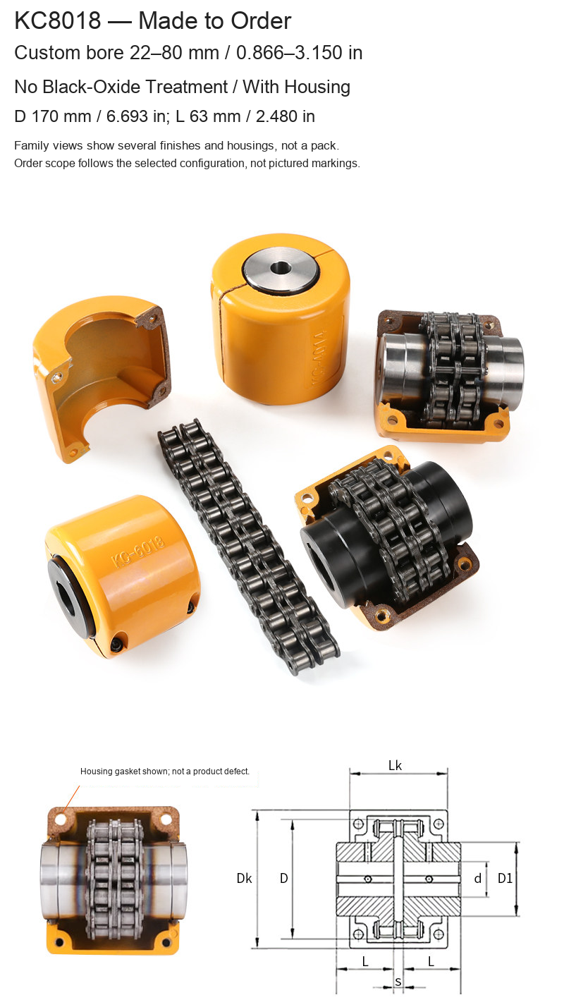
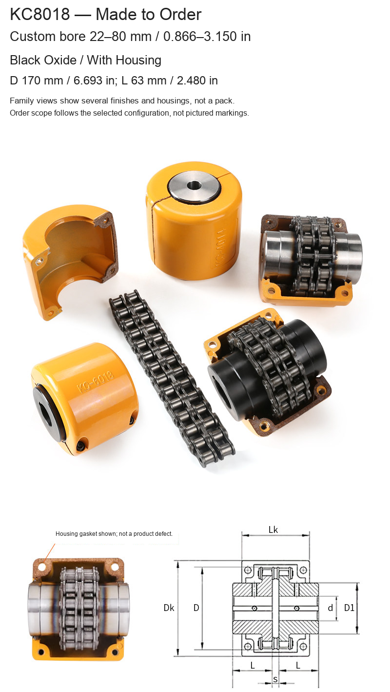
| KC8018 | 22–80 / 0.866–3.150 | 170 / 6.693 | 63 / 2.480 |
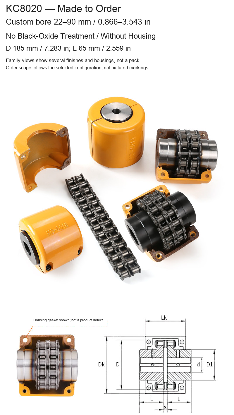
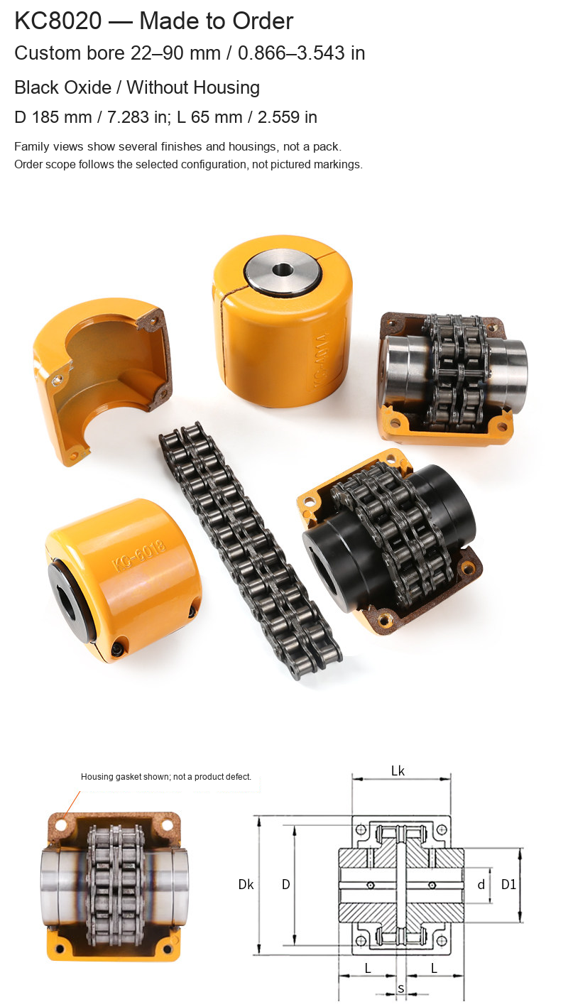
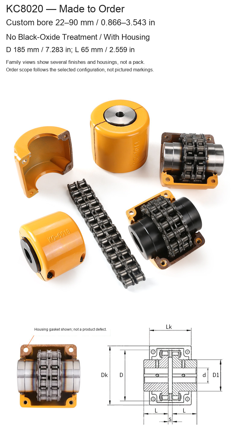
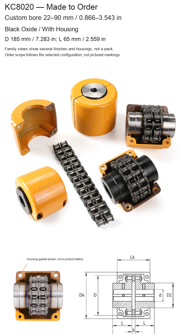
| KC8020 | 22–90 / 0.866–3.543 | 185 / 7.283 | 65 / 2.559 |
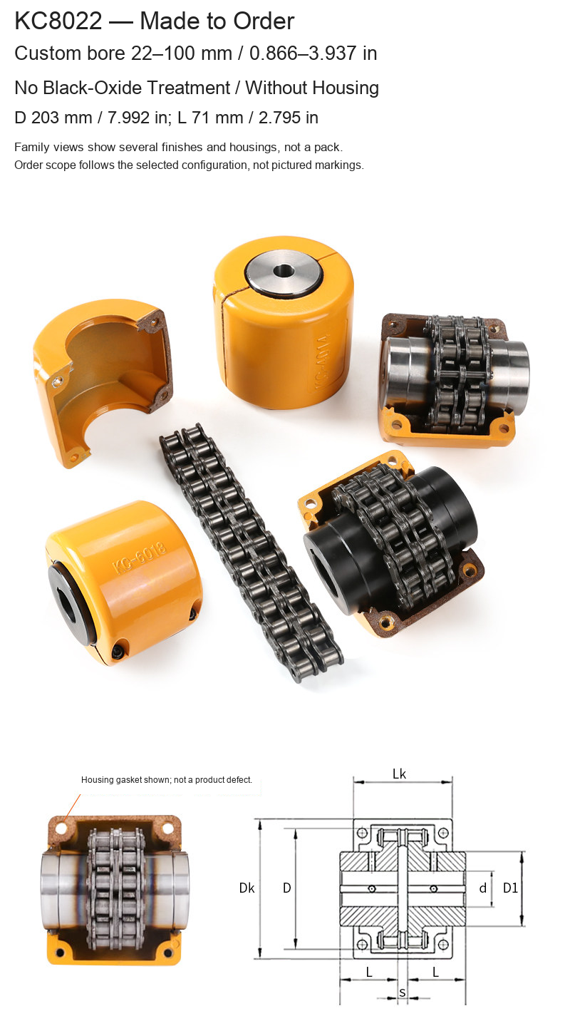
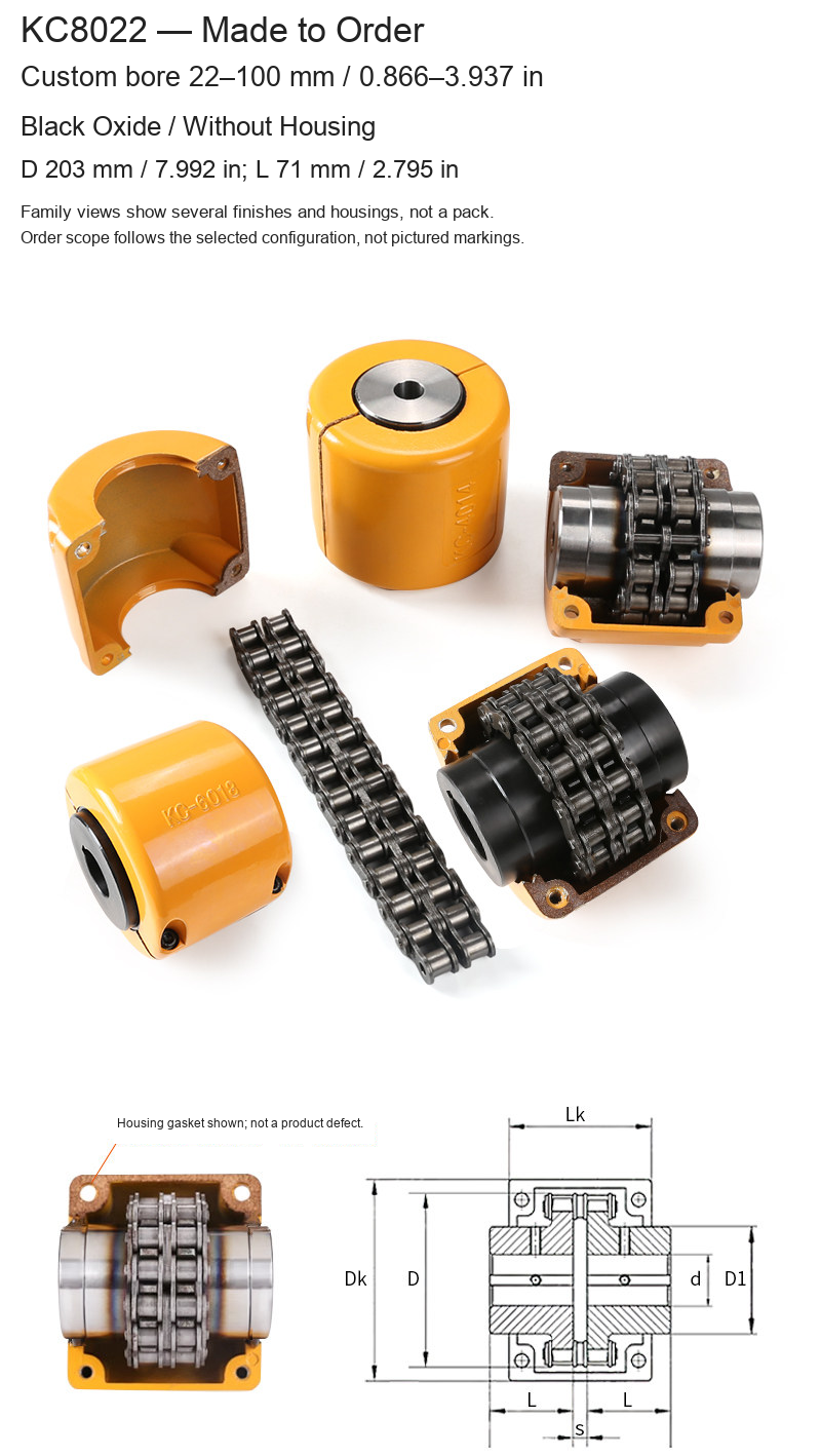
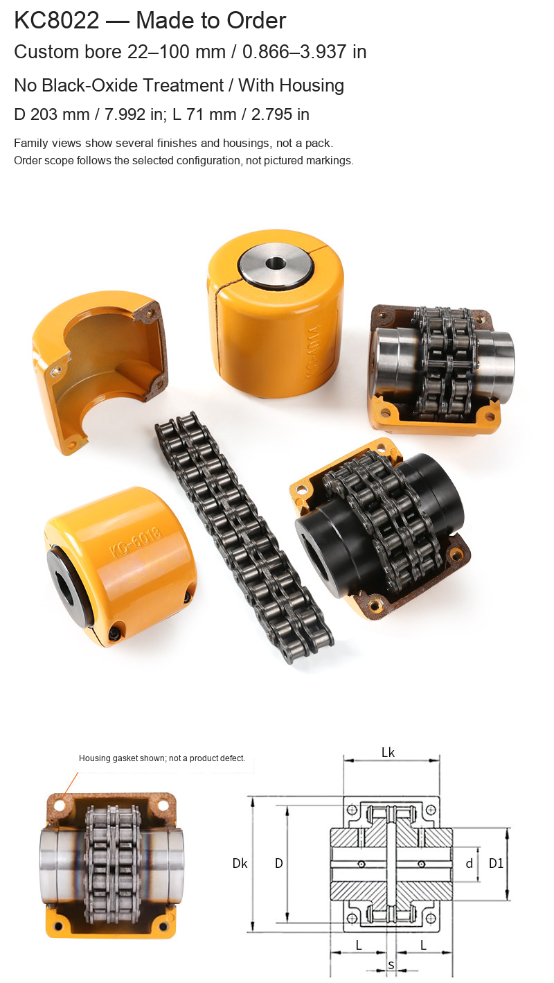
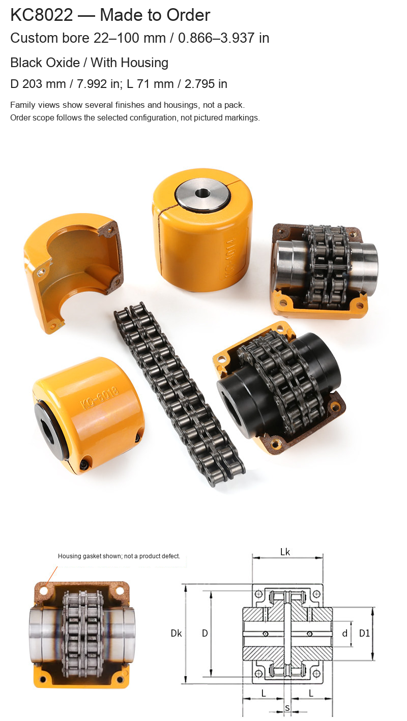
| KC8022 | 22–100 / 0.866–3.937 | 203 / 7.992 | 71 / 2.795 |
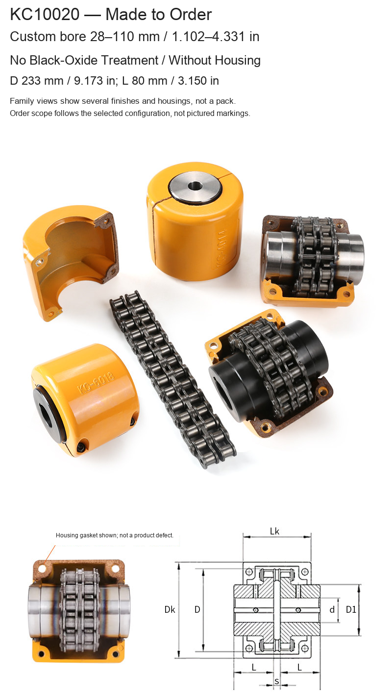
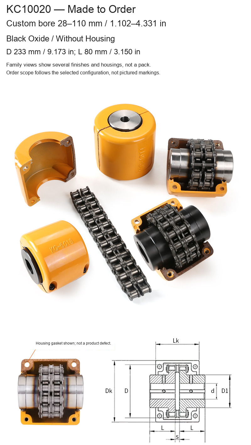
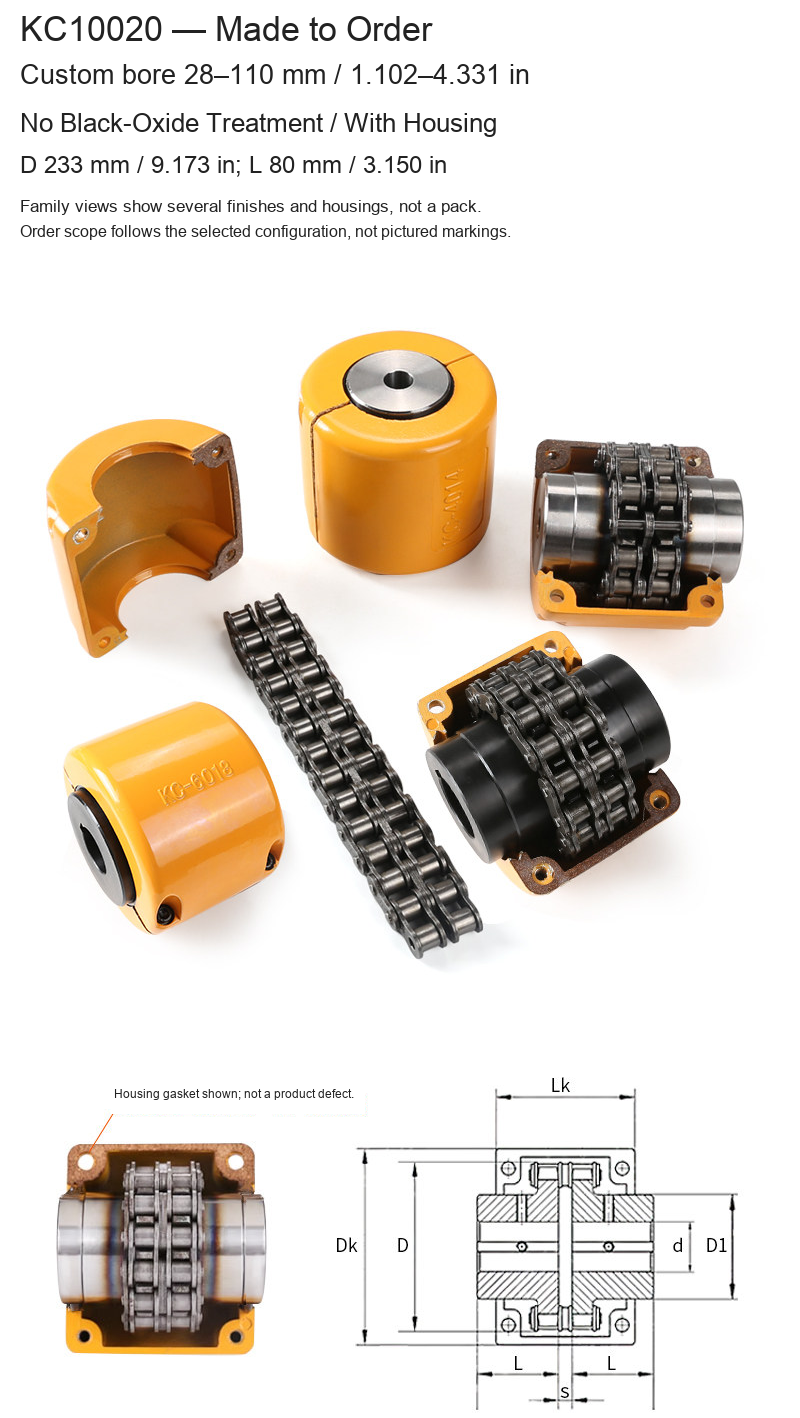
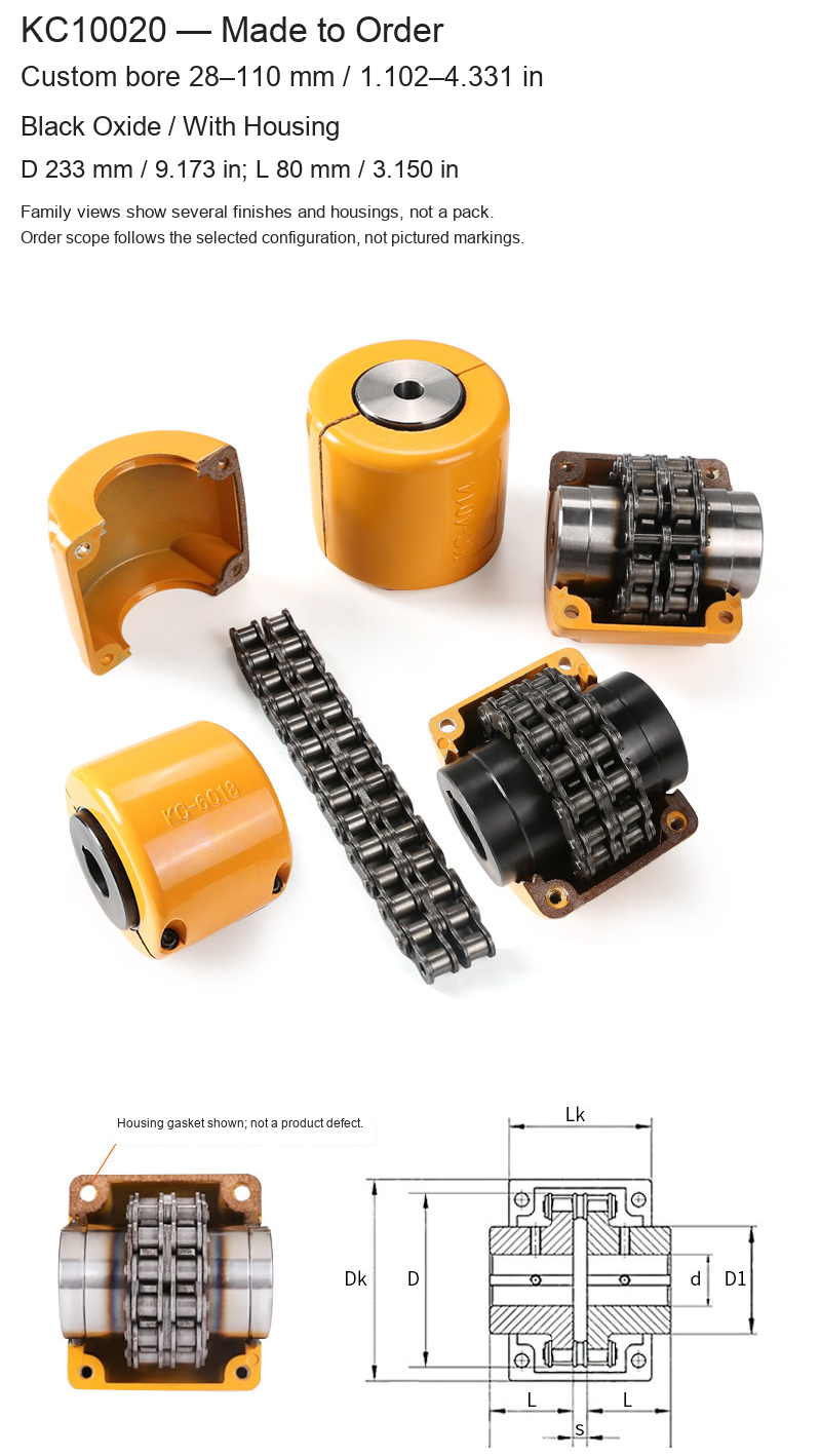
| KC10020 | 28–110 / 1.102–4.331 | 233 / 9.173 | 80 / 3.150 |
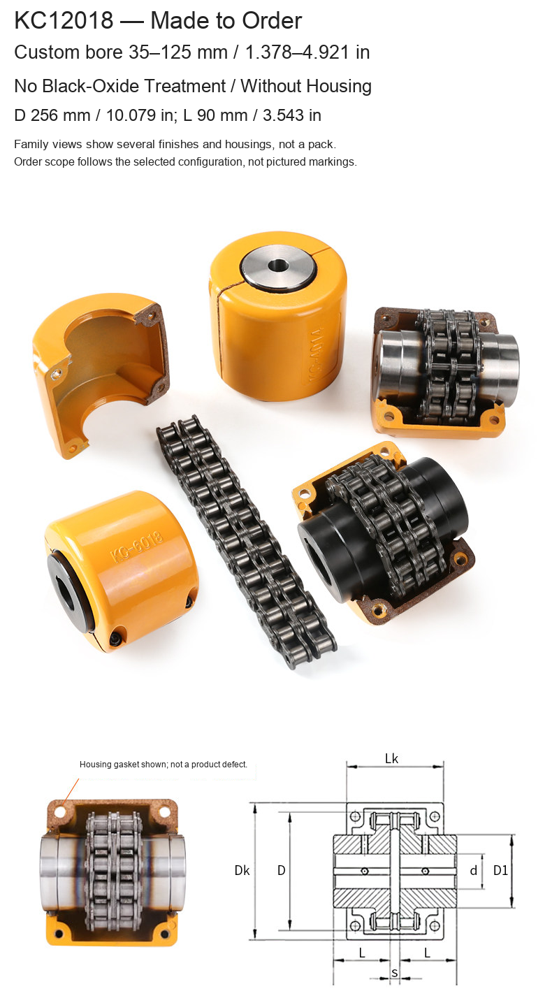
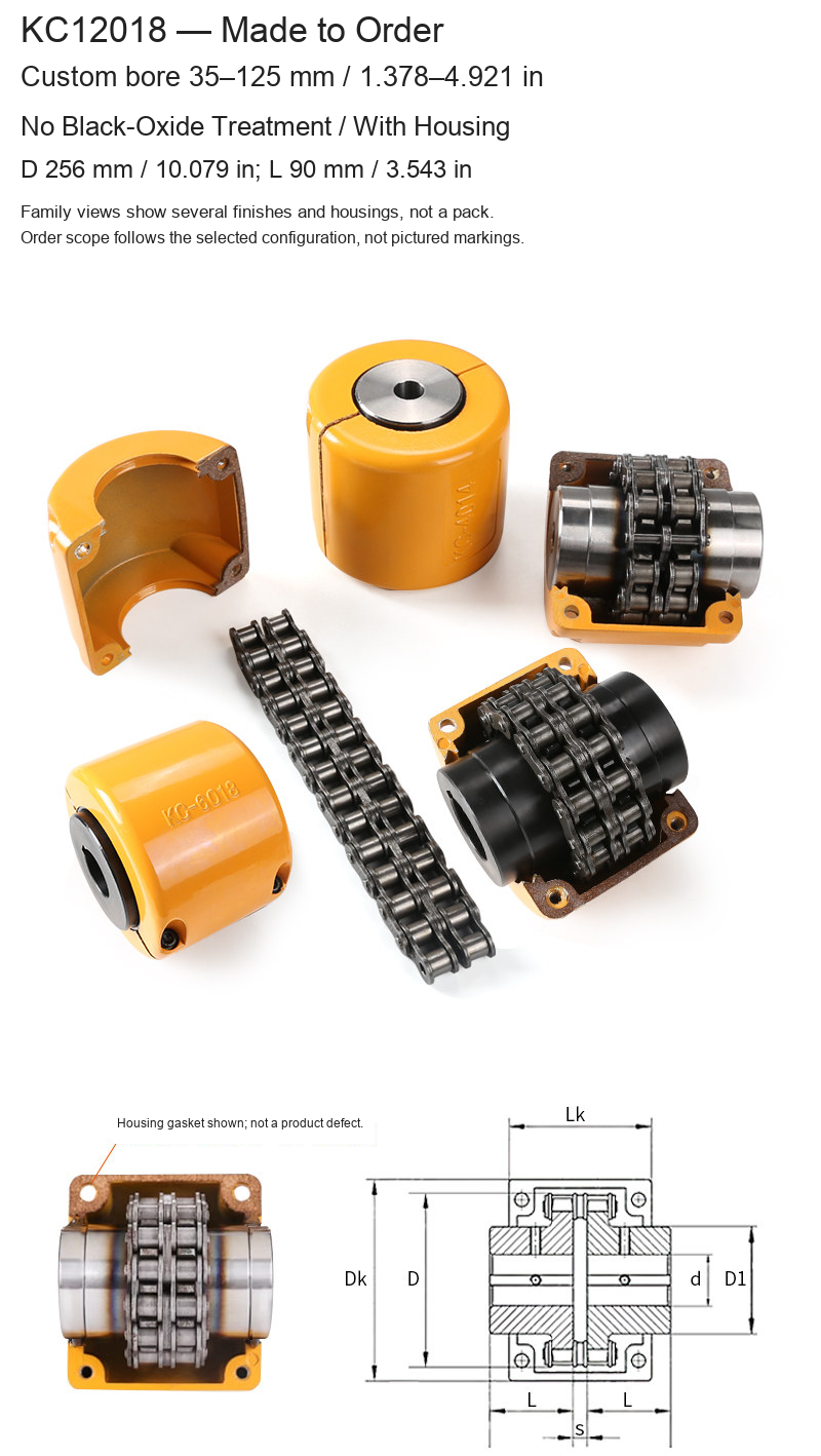
| KC12018 | 35–125 / 1.378–4.921 | 256 / 10.079 | 90 / 3.543 |
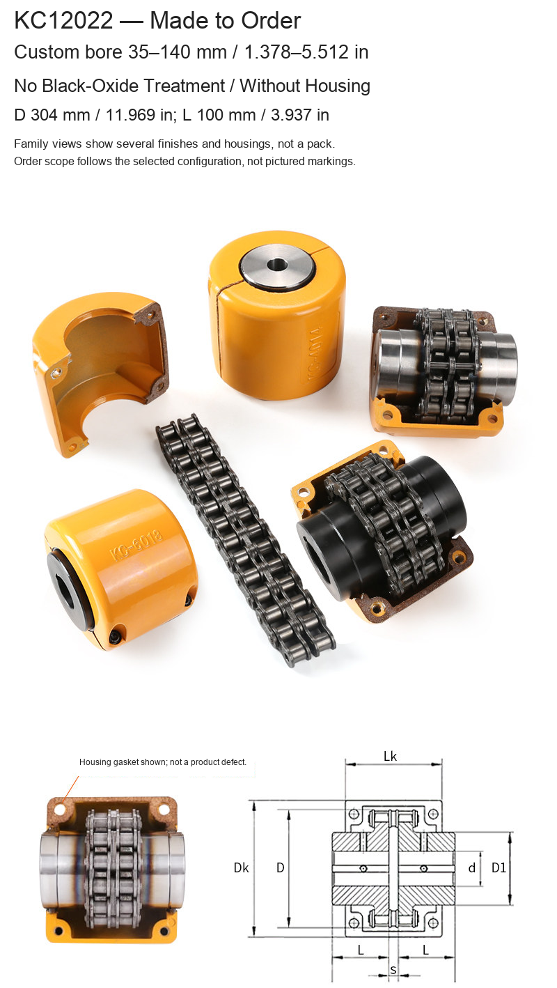
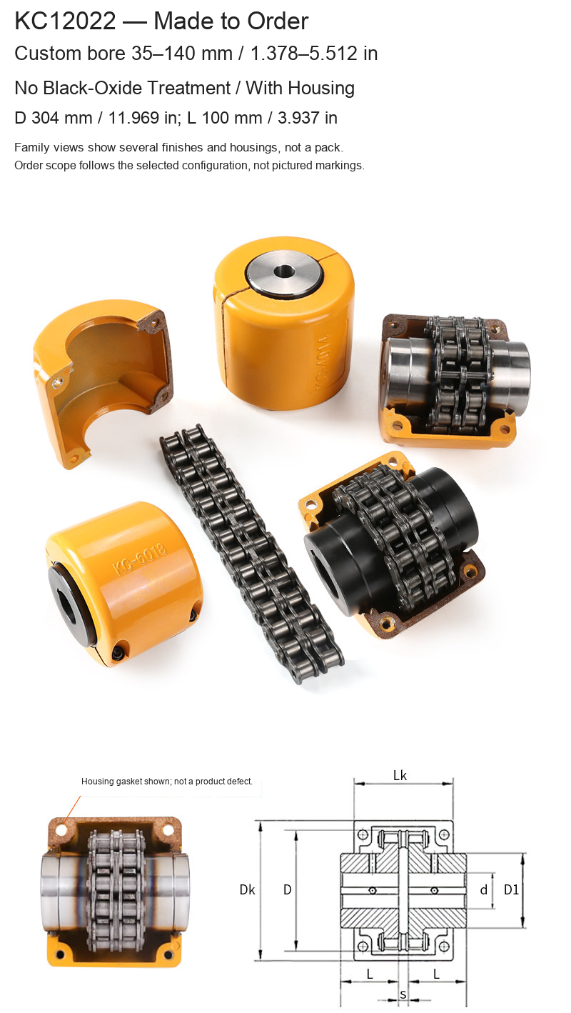
| KC12022 | 35–140 / 1.378–5.512 | 304 / 11.969 | 100 / 3.937 |
Original Dimension and Chain Tables
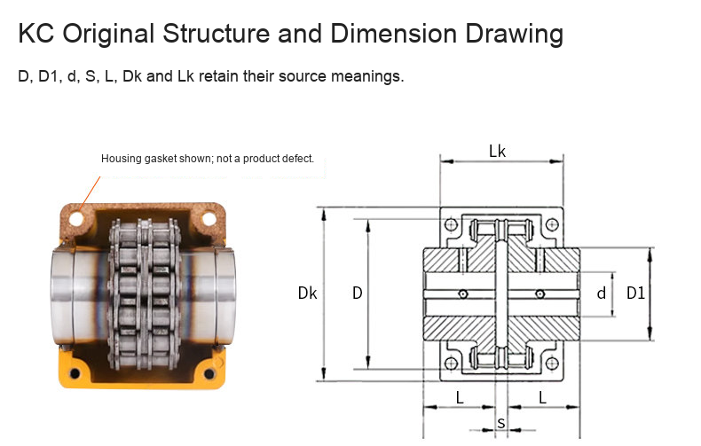
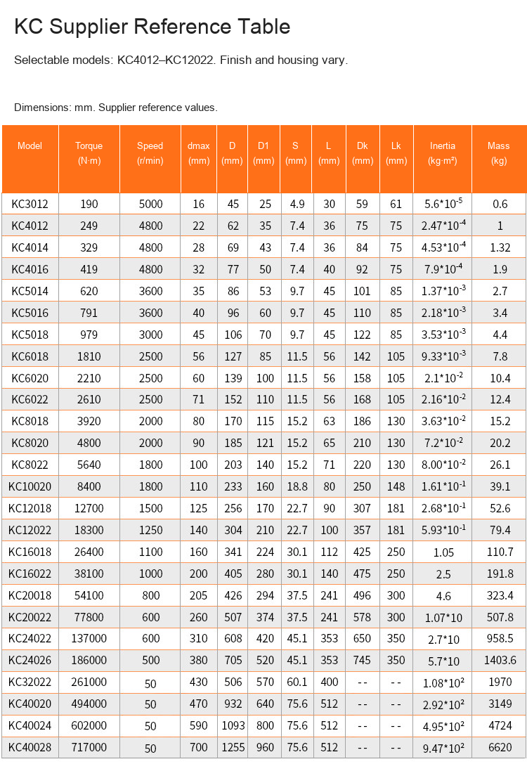
The original KC drawing and numeric table rows are retained. D/D1, shaft bore d, axial gap S, hub length L and housing dimensions Dk/Lk keep their original drawing meanings. dmax is the supplier's maximum bore reference; confirm the required finished interfaces. Supplier nominal torque, speed, inertia and mass are reference figures, not an independent test certificate or a verified rating for every custom configuration.
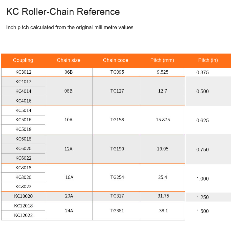
The KC table includes other unpriced sizes for reference; only the fifty-six selectable configurations are offered here. The chain table retains its original millimetre pitches, chain sizes and chain codes. Inch pitches are calculated as millimetres divided by 25.4, including 31.75 mm = 1.250 in.
Photographs and Supply Scope
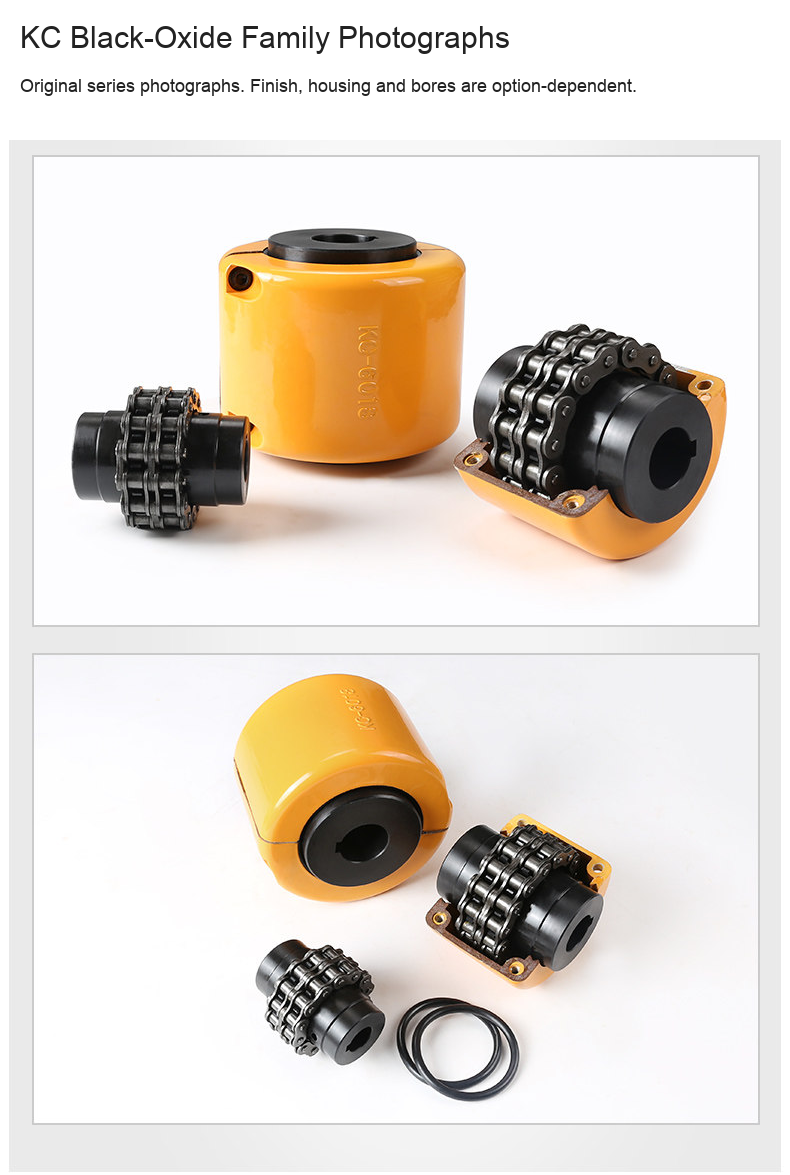
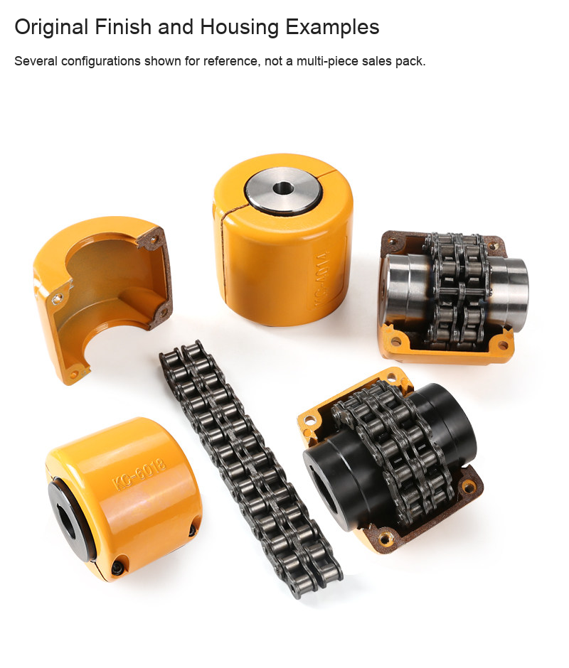
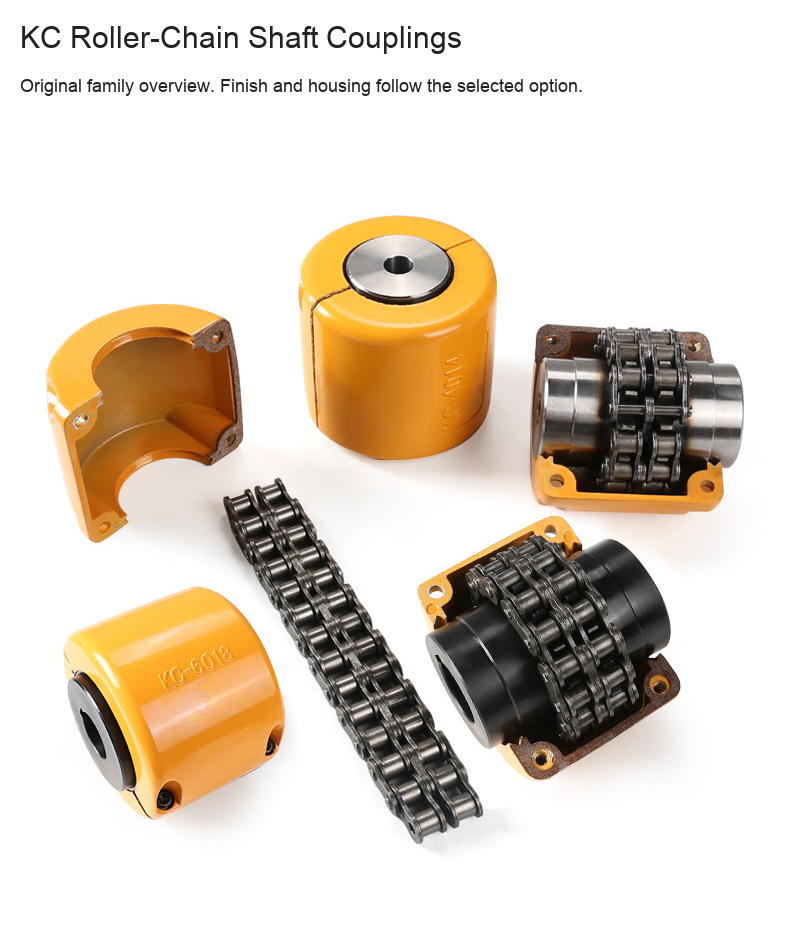
Original family photographs show different finishes, open/closed housing examples and components. Pictured engravings and multiple assemblies are representative source views, not the selected model marking or a multi-piece pack. Finished bores, finish and included housing follow the selected option and confirmed drawing. Standard component layout does not establish a specific pin, gasket or chain-spare quantity. Shafts and motors are not included.
Selection, Installation and Maintenance
Confirm torque, speed, shaft interfaces, alignment, working space and guarding against the supplied drawing. Isolate equipment before assembly, verify the shaft fits/keyways and fastening, and confirm chain and lubrication requirements for the actual application. No quantified misalignment allowance, universal interchangeability, service-life or maintenance-free rating is asserted.