JH, JHC and JHCS Aluminum Oldham Couplings
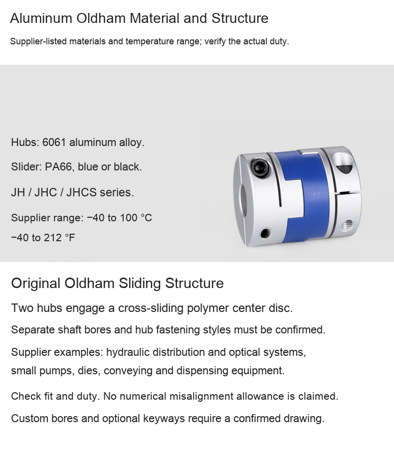
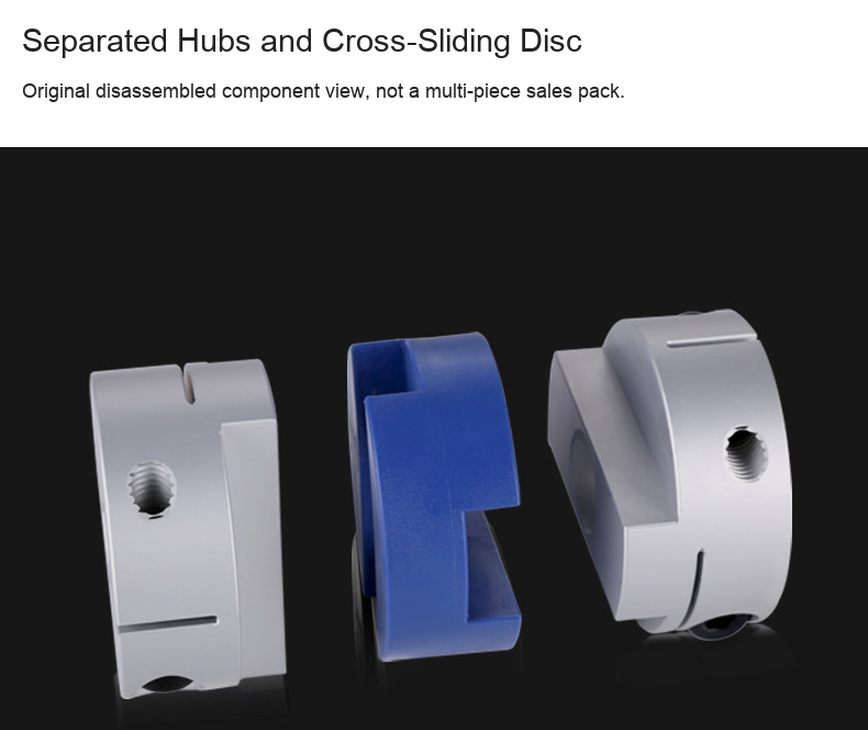
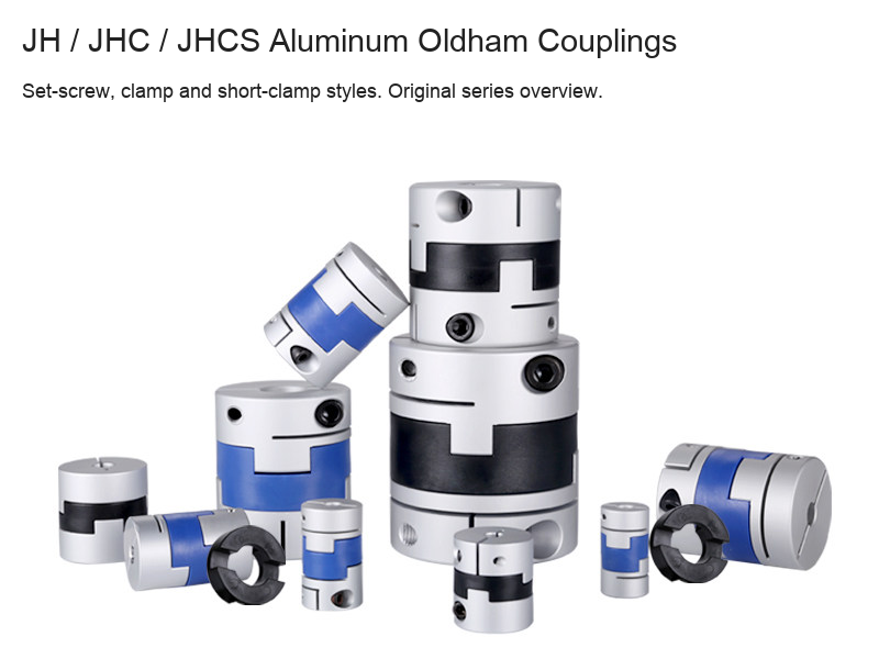
Three-piece Oldham-style shaft couplings with 6061 aluminum-alloy hubs and a PA66 cross-sliding center disc. Choose the fastening style, outside diameter, overall length and slider color, then confirm both finished bore dimensions. Listed bore ranges describe machining scope, not a supplied fixed bore pair.
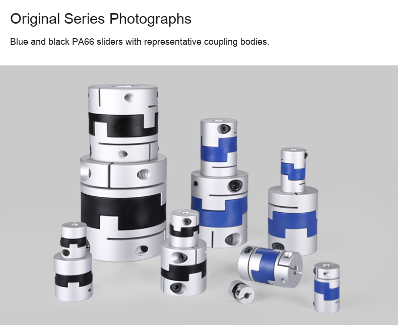
Hub Styles and Slider Colors
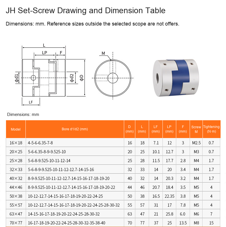
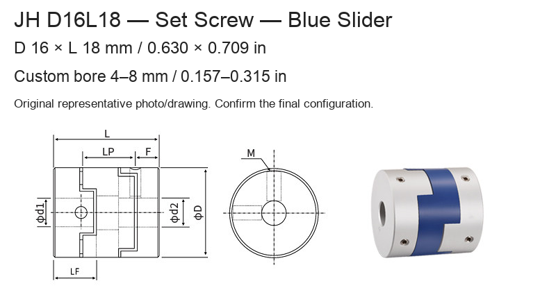
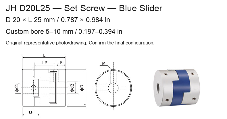
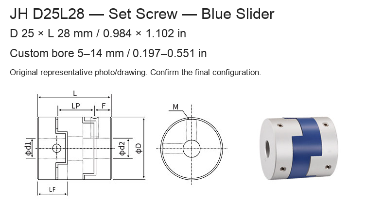
- JH: radial set-screw hub.
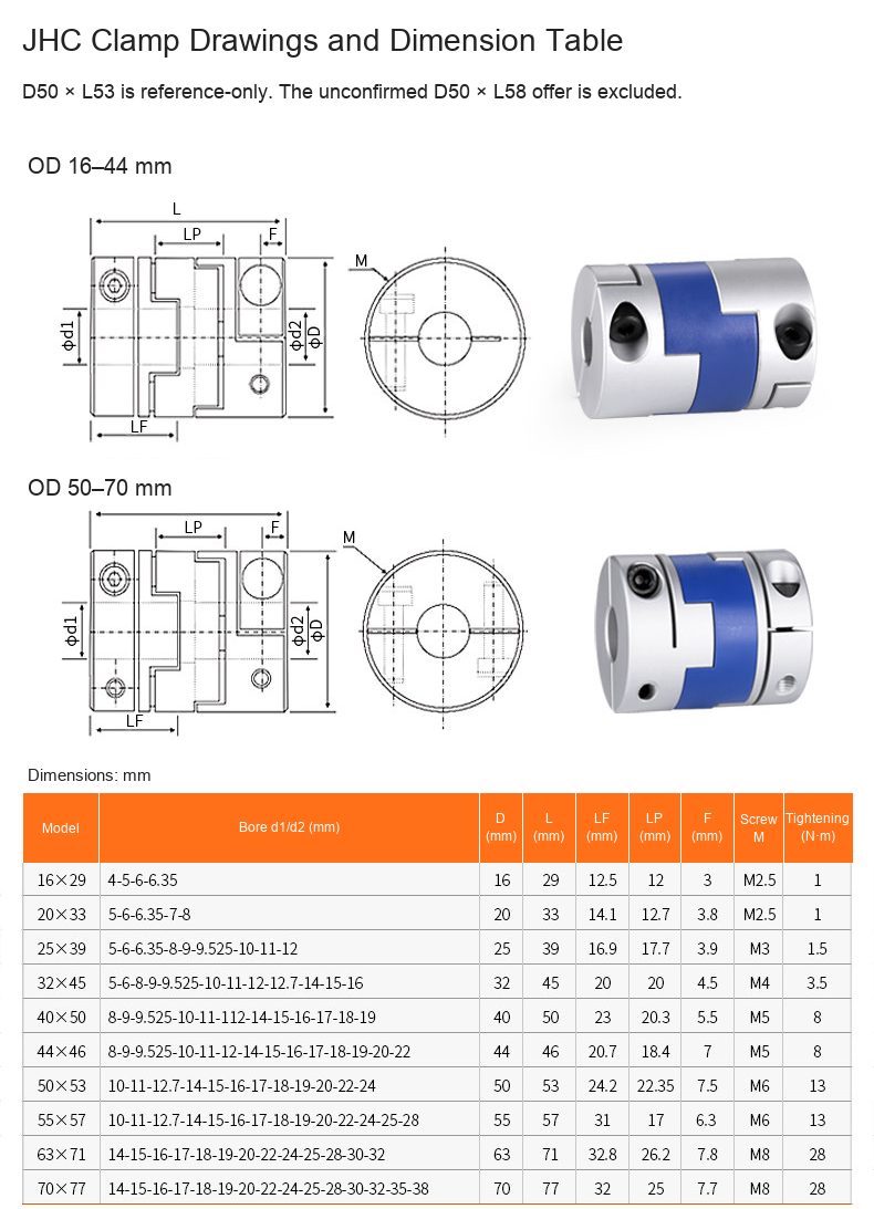
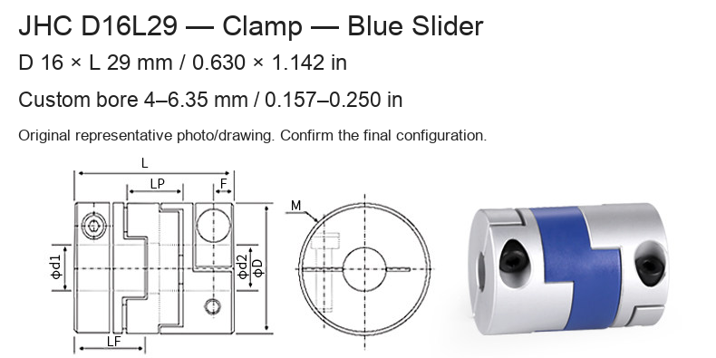
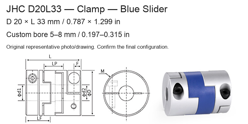
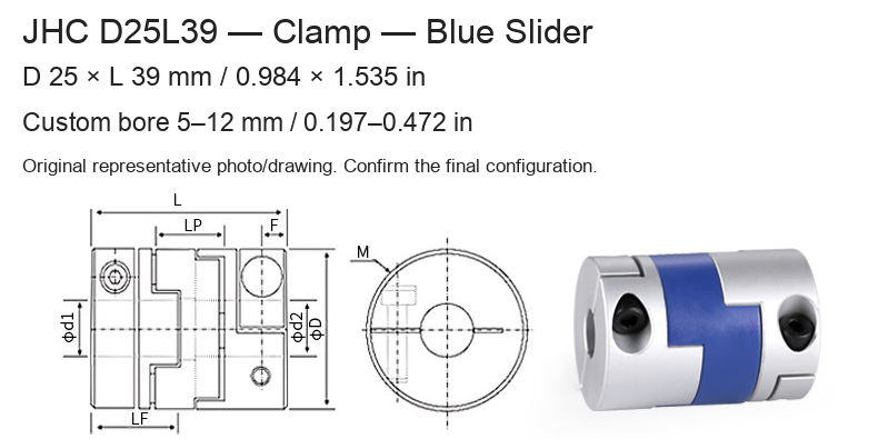
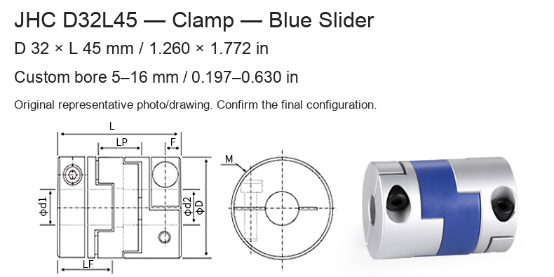
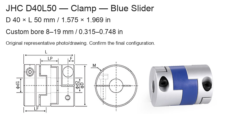
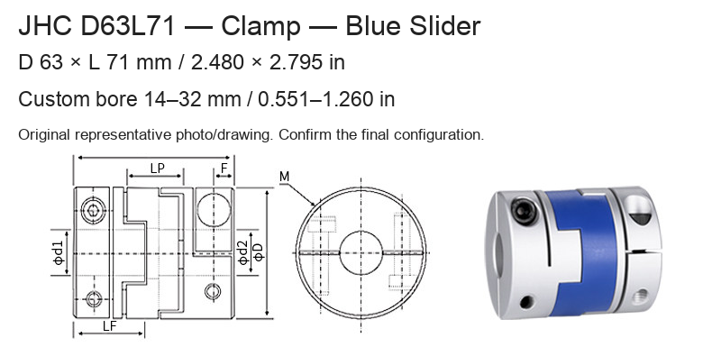
- JHC: clamp hub. The original drawings show different fastener arrangements for smaller and larger outside diameters.
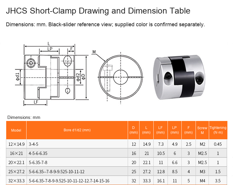
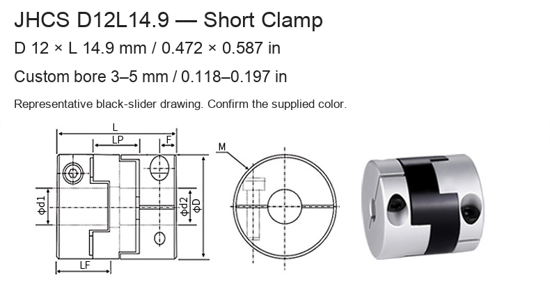
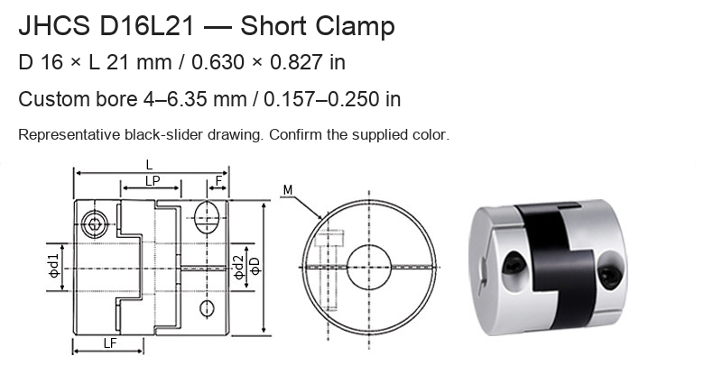
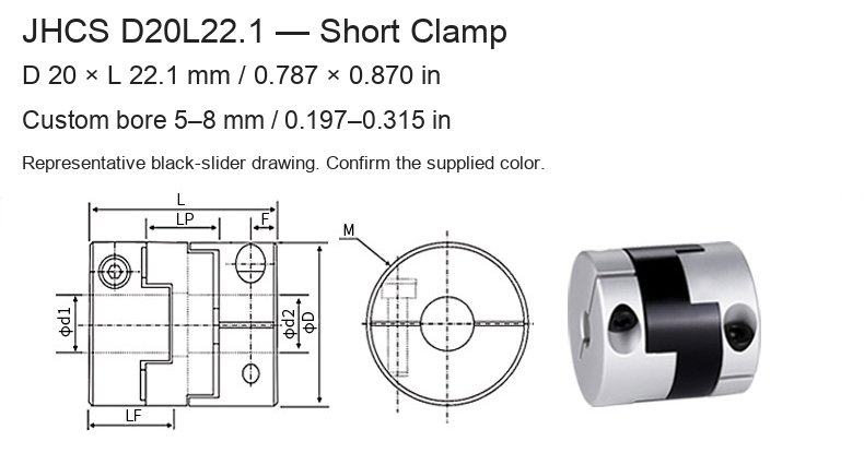
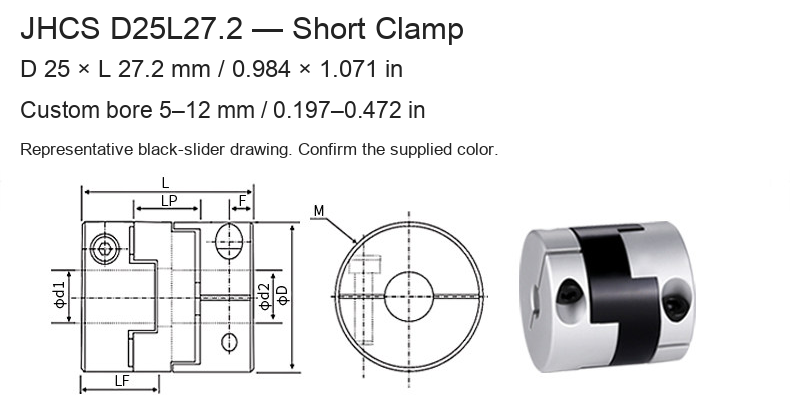
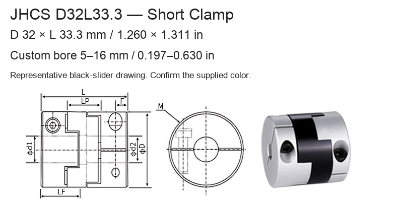
- JHCS: short-body clamp hub with a black slider in the supplied series drawing.
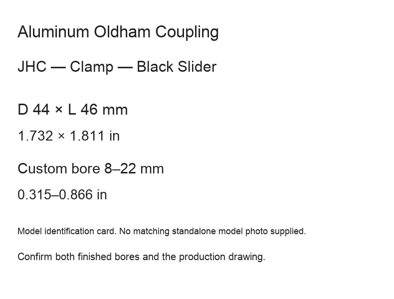
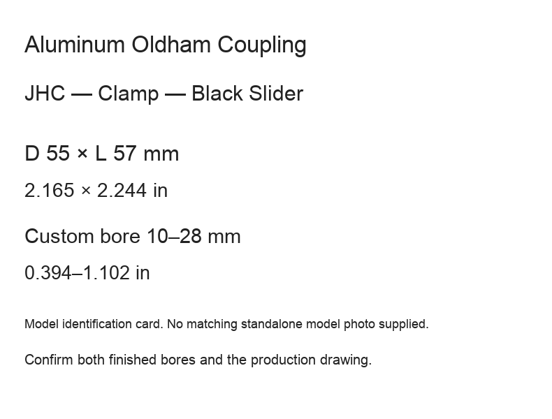
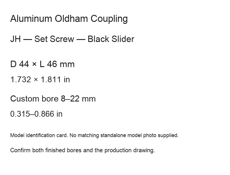
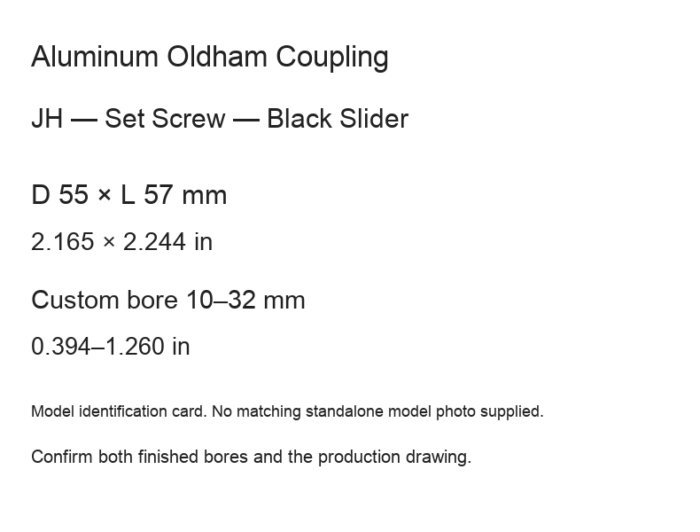
- Blue and explicitly marked black slider offers are identified separately. The four black D44/D55 normal-body offers use model identification cards because matching standalone model photographs were not supplied.
The short-clamp SKU labels do not fix the slider color. The original drawing shows a black example; confirm the actual supplied color with the order rather than inferring it from the reference view.
Custom Ordering
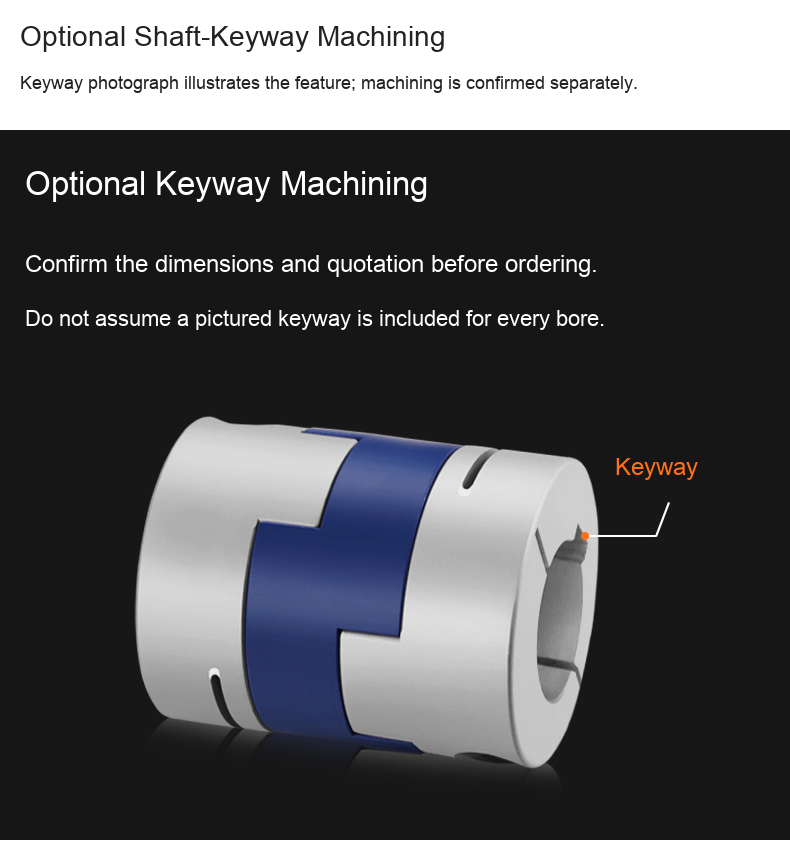
Provide d1/d2, bore tolerances, shaft engagement and any requested keyway dimensions in Order requirements or contact BOLTTE. Confirm the machining drawing before production. Keyways require separate specification and quotation; the pictured example does not establish inclusion for every bore. Custom processing time is confirmed separately from shipping transit estimates.
Material and Operating Scope
The supplier specifies 6061 aluminum-alloy hubs, PA66 sliders in blue or black, and a temperature range −40 to 100 °C (−40 to 212 °F). Examples of use listed in the supplied material include hydraulic distribution and optical systems, small pumps, dies, conveying and dispensing equipment. Check the actual load, environment and shaft fit for the confirmed assembly. No certification, imported-material guarantee or universal machine fit is asserted.
Available Dimensions
Millimetres are authoritative; inch equivalents are rounded to three decimals.
| Series / style / slider | D × L (mm / in) | Custom bore range (mm / in) |
|---|---|---|
| JHC Clamp, Blue | 16 × 29 / 0.630 × 1.142 | 4–6.35 / 0.157–0.250 |
| JHC Clamp, Blue | 20 × 33 / 0.787 × 1.299 | 5–8 / 0.197–0.315 |
| JHC Clamp, Blue | 25 × 39 / 0.984 × 1.535 | 5–12 / 0.197–0.472 |
| JHC Clamp, Blue | 32 × 45 / 1.260 × 1.772 | 5–16 / 0.197–0.630 |
| JHC Clamp, Blue | 40 × 50 / 1.575 × 1.969 | 8–19 / 0.315–0.748 |
| JHC Clamp, Blue | 63 × 71 / 2.480 × 2.795 | 14–32 / 0.551–1.260 |
| JHC Clamp, Black | 44 × 46 / 1.732 × 1.811 | 8–22 / 0.315–0.866 |
| JHC Clamp, Black | 55 × 57 / 2.165 × 2.244 | 10–28 / 0.394–1.102 |
| JH Set Screw, Blue | 16 × 18 / 0.630 × 0.709 | 4–8 / 0.157–0.315 |
| JH Set Screw, Blue | 20 × 25 / 0.787 × 0.984 | 5–10 / 0.197–0.394 |
| JH Set Screw, Blue | 25 × 28 / 0.984 × 1.102 | 5–14 / 0.197–0.551 |
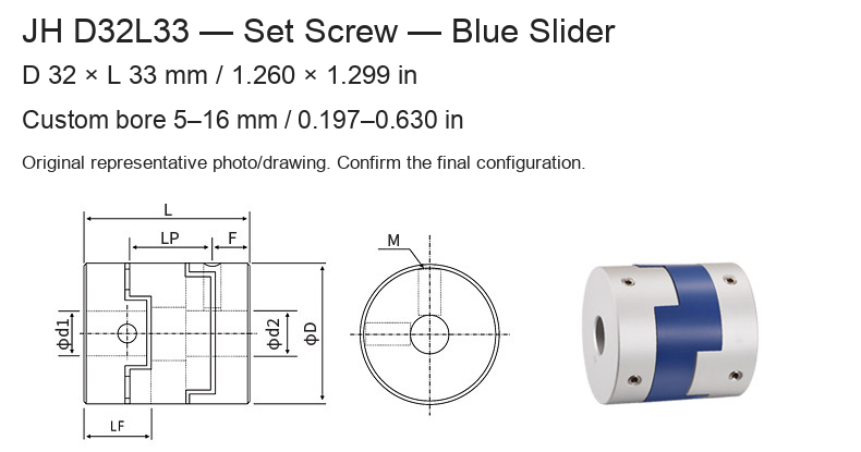
| JH Set Screw, Blue | 32 × 33 / 1.260 × 1.299 | 5–16 / 0.197–0.630 |
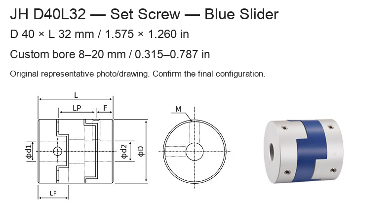
| JH Set Screw, Blue | 40 × 32 / 1.575 × 1.260 | 8–20 / 0.315–0.787 |
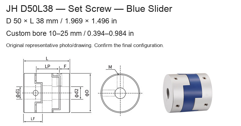
| JH Set Screw, Blue | 50 × 38 / 1.969 × 1.496 | 10–25 / 0.394–0.984 |
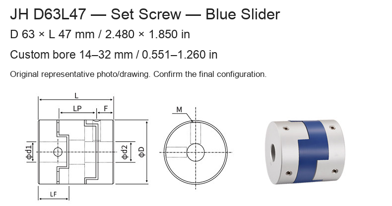
| JH Set Screw, Blue | 63 × 47 / 2.480 × 1.850 | 14–32 / 0.551–1.260 |
| JH Set Screw, Black | 44 × 46 / 1.732 × 1.811 | 8–22 / 0.315–0.866 |
| JH Set Screw, Black | 55 × 57 / 2.165 × 2.244 | 10–32 / 0.394–1.260 |
| JHCS Short Clamp, Confirm with order | 12 × 14.9 / 0.472 × 0.587 | 3–5 / 0.118–0.197 |
| JHCS Short Clamp, Confirm with order | 16 × 21 / 0.630 × 0.827 | 4–6.35 / 0.157–0.250 |
| JHCS Short Clamp, Confirm with order | 20 × 22.1 / 0.787 × 0.870 | 5–8 / 0.197–0.315 |
| JHCS Short Clamp, Confirm with order | 25 × 27.2 / 0.984 × 1.071 | 5–12 / 0.197–0.472 |
| JHCS Short Clamp, Confirm with order | 32 × 33.3 / 1.260 × 1.311 | 5–16 / 0.197–0.630 |
Original Drawings and Reference Data
The original drawings retain D, L, LF, LP, F, bore d1/d2 and fastener M notation. Dimension and tightening-torque reference numbers are retained without redrawing the products. Reference rows outside the selectable offers are not additional sale configurations. The JHC D50 × L53 table row is reference-only; an unconfirmed D50 × L58 source offer is not listed.
Tightening-torque figures in the dimension tables are supplier references, not transmitted-torque capacity ratings. No numerical angular, radial or axial misalignment allowance, torque-capacity rating or rotational-speed rating is claimed for these offers. Confirm the applicable limits and assembly requirements before ordering.
Installation and Inspection
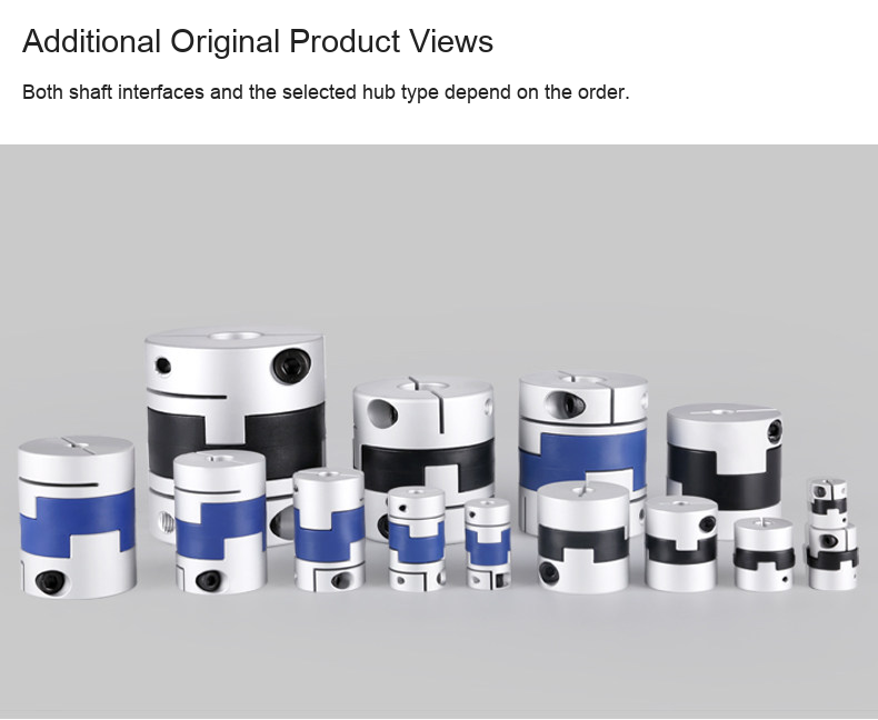
Check shaft fit, alignment, fastening access and installation space against the confirmed drawing. Isolate equipment before fitting or servicing. Follow the supplied fastener and slider inspection/replacement requirements. Original photographs show representative hub types and colors; they do not establish exact custom bores or a multi-piece sales pack. Shafts and motors are not included.