


GICG Stainless Steel Parallel-Slot Clamp Couplings
GICG couplings have a one-piece stainless steel body with parallel machined slots and split-clamp shaft retention. Select the body diameter and length, then specify the finished bores d1 and d2 for the two shafts. A bore range describes configurable options, not a self-adjusting hole.
Models and Dimensions
Nominal metric dimensions are primary. Inch equivalents are approximate, rounded to three decimal places. Metric clamp-screw threads are not converted to imperial threads.
| Model and offered bore range | Outside diameter | Length | Clamp screw | Source tightening torque (N m) |
|---|---|---|---|---|
| GICG-40x56 / Bore 10-20 mm | 40 mm / 1.575 in | 56 mm / 2.205 in | M5 | 8 |
| GICG-16x18 / Bore 3-6.35 mm | 16 mm / 0.630 in | 18 mm / 0.709 in | M2.5 | 1 |
| GICG-16x23 / Bore 3-6.35 mm | 16 mm / 0.630 in | 23 mm / 0.906 in | M2.5 | 1 |
| GICG-20x20 / Bore 4-10 mm | 20 mm / 0.787 in | 20 mm / 0.787 in | M3 | 1.5 |
| GICG-20x26 / Bore 4-10 mm | 20 mm / 0.787 in | 26 mm / 1.024 in | M3 | 1.5 |
| GICG-25x25 / Bore 5-12 mm | 25 mm / 0.984 in | 25 mm / 0.984 in | M3 | 1.5 |
| GICG-25x31 / Bore 5-12 mm | 25 mm / 0.984 in | 31 mm / 1.220 in | M3 | 1.5 |
| GICG-32x32 / Bore 8-16 mm | 32 mm / 1.260 in | 32 mm / 1.260 in | M4 | 3.5 |
| GICG-32x41 / Bore 8-16 mm | 32 mm / 1.260 in | 41 mm / 1.614 in | M4 | 3.5 |
Construction
The original photograph shows the one-piece slotted body, shaft-clamp splits and screw access. The source engineering image and product-detail panel identify stainless steel. An exact stainless grade, hardness, certified origin and corrosion rating are not established. This is not an aluminum helical coupling, a separate spring-steel coupling, a bellows coupling or a polymer-insert coupling.
Configurable Shaft Bores
Specify both finished bores and the required shaft fit before ordering. The supplier lists H7 as a bore-tolerance reference; confirm the actual machining and inspection requirements for your shafts. One selected option is one coupling, not a pair or a separately priced machining service. For 40x56 the offered range remains 10-20 mm even though the general catalogue includes 8 mm. Not every intermediate diameter is necessarily stocked. Keyways and special bores require a confirmed drawing and are not automatically included.
Catalogue Technical Reference
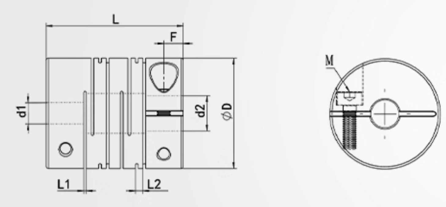
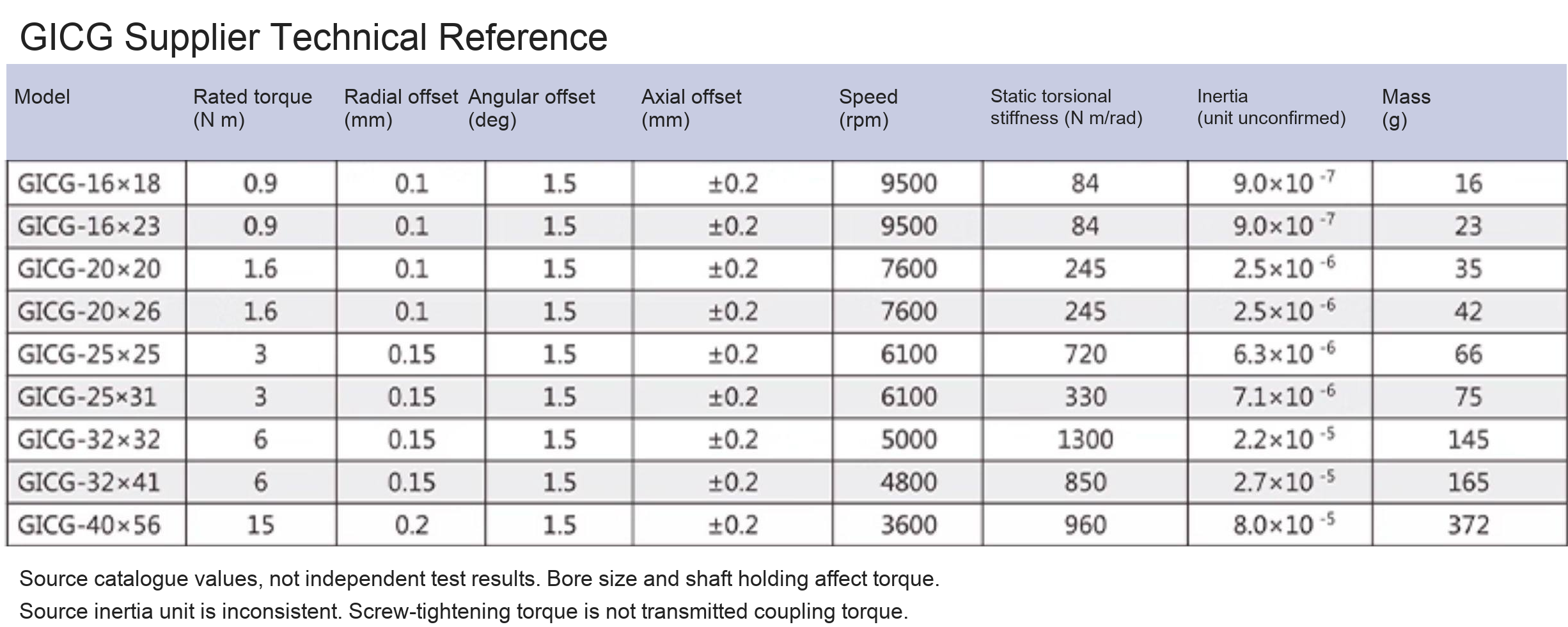
The original dimension and technical table cells below retain the source numbers and model codes. Catalogue data include nominal torque, permissible radial/angular/axial offset, speed, static torsional stiffness and mass. Confirm their applicability to the finished bores and duty before selection. Shaft holding and bore configuration can limit transmitted torque. Screw-tightening torque is not the coupling torque rating. The source inertia unit is inconsistent and is marked unconfirmed; do not treat these values as verified inertia specifications. L1 and L2 labels are retained as source drawing references, not inferred shaft-insertion depths.
Original Photographs and Drawings
The source photograph is engraved GICG-40X56 and is used only for that model. The other selectable models use the original GICG engineering drawing with their own nominal dimensions. These are catalogue illustrations, not individual finished-bore photographs or scale drawings. The slot close-up is taken from the original 40x56 photograph without redrawing the product. Supplier branding and unsupported certification or promotional claims are omitted.
Installation and Application
The source identifies encoder and compact drive connections. Check both shafts, available body clearance, alignment, clamp access, torque and speed for the actual equipment. Keep shaft insertion clear of the flexible section and follow the confirmed fastening procedure. Isolate power before installation or maintenance, secure the drive and provide suitable guarding. No fixed lead time, lifetime guarantee, zero-backlash test or independent certification is represented.



Modelo / configuración / SKU
| Modelo / configuración | SKU |
|---|---|
| GICG-40x56 / Bore 10-20 mm | 4613959520738 |
| GICG-16x18 / Bore 3-6.35 mm | 4613959520730 |
| GICG-16x23 / Bore 3-6.35 mm | 4613959520731 |
| GICG-20x20 / Bore 4-10 mm | 4613959520732 |
| GICG-20x26 / Bore 4-10 mm | 4613959520733 |
| GICG-25x25 / Bore 5-12 mm | 4613959520734 |
| GICG-25x31 / Bore 5-12 mm | 4613959520735 |
| GICG-32x32 / Bore 8-16 mm | 4613959520736 |
| GICG-32x41 / Bore 8-16 mm | 4613959520737 |