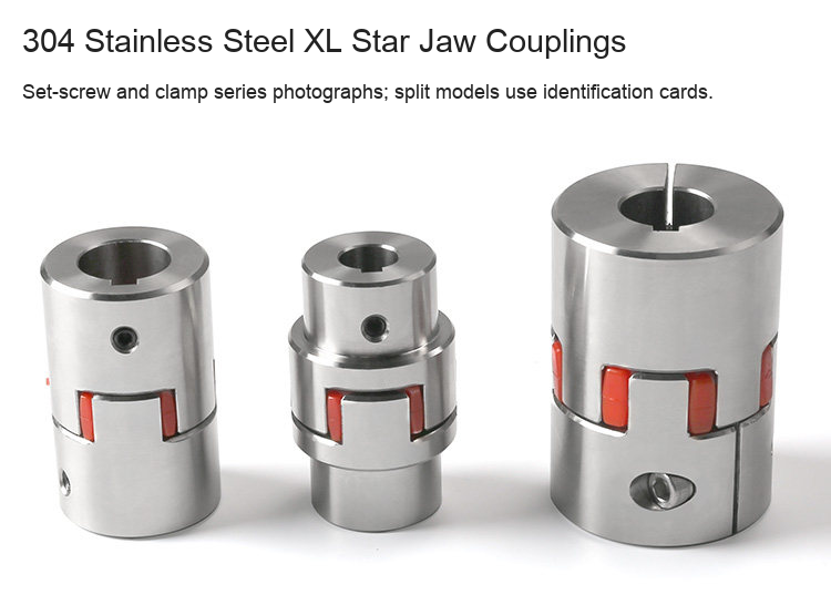
304 Stainless Steel XL Star Jaw Couplings
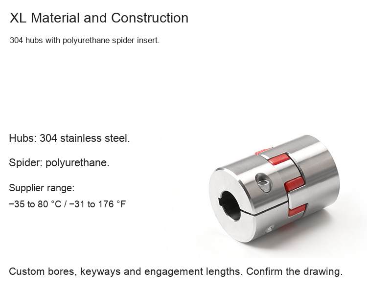
Elastic jaw couplings with 304 stainless-steel hubs and a polyurethane spider insert. Select the exact hub fastening type and body size, then confirm both finished shaft interfaces before production. Listed bore ranges describe custom machining scope, not a supplied fixed bore pair.
Ordering and Hub Types
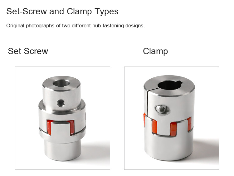
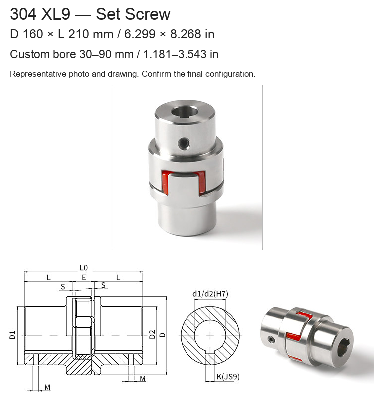
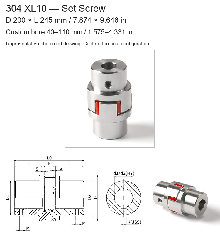
- Set Screw: regular hub form with a radial set screw.
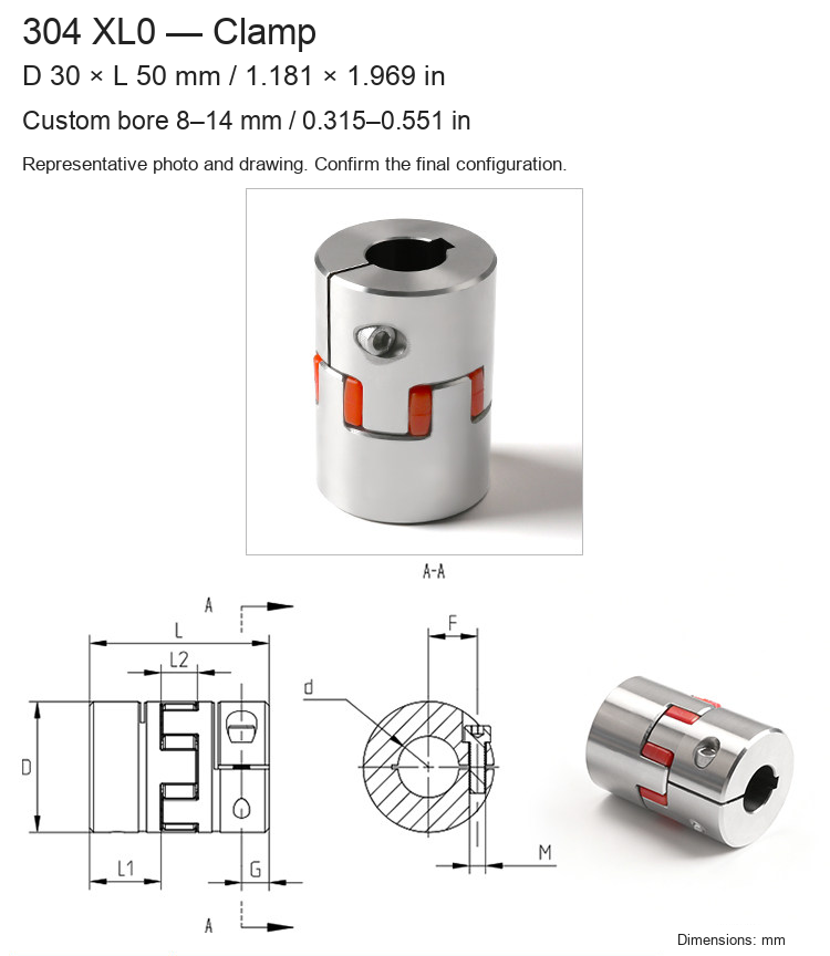
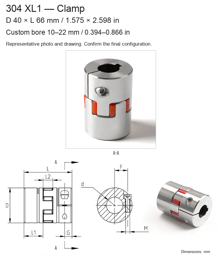
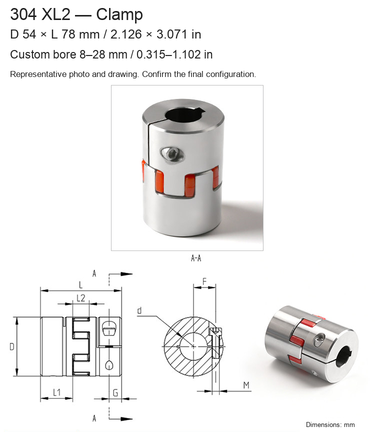
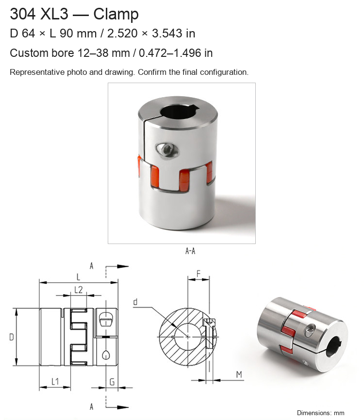
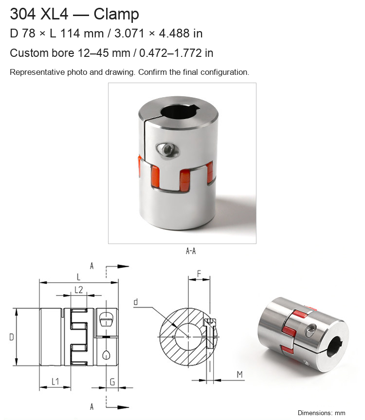
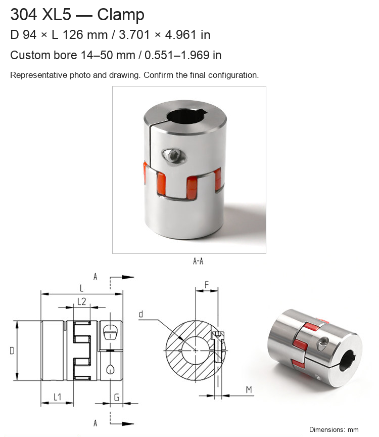
- Clamp: slotted hub clamped by a socket-head fastener.
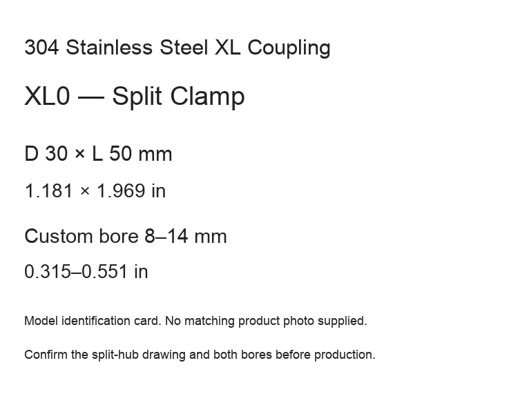
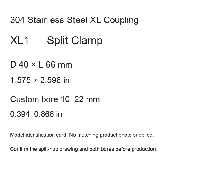
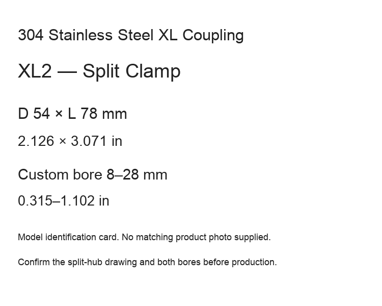
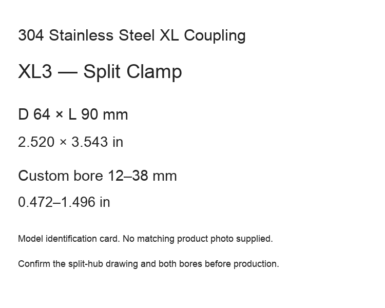
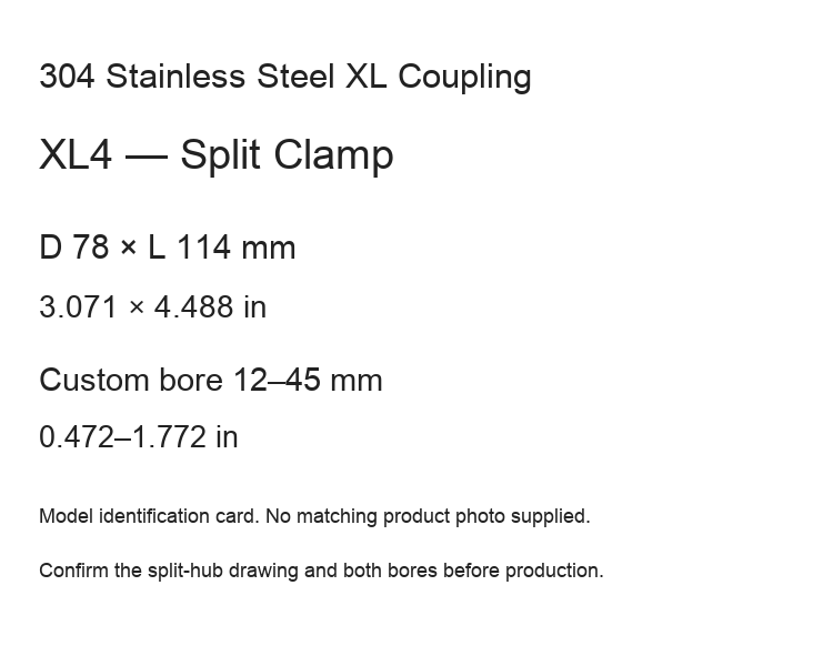
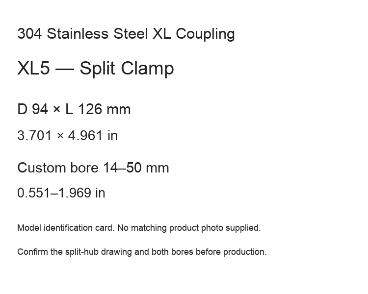
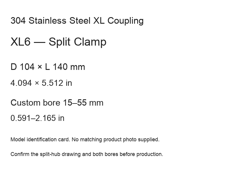
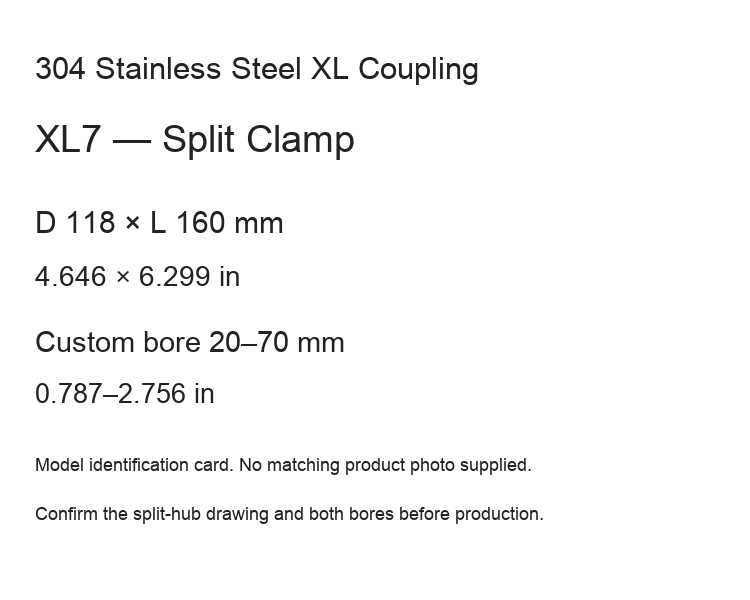
- Split Clamp: the source identifies a separable clamp version. Matching product photographs were not supplied; its variant image is a model identification card. Confirm the split-hub construction drawing before production.
Provide d1/d2, tolerances, keyway dimensions, engagement lengths and the complete drawing in Order requirements or contact BOLTTE. Any requirement outside the selected machining range needs separate confirmation. Custom processing time is confirmed separately from shipping transit estimates.
Material and Assembly
The product specification identifies 304 stainless-steel hubs, a polyurethane elastic insert and a supplier-listed temperature range −35 to 80 °C (−31 to 176 °F). Reference figures must be checked for the actual bore, hub construction, insert and operating duty. No universal interchangeability or maintenance-free rating is specified.
Available Configurations
Millimetres are authoritative; inch equivalents are rounded to three decimals. Set-screw XL4 is not offered pending bore-range confirmation.
| Model / type | D × L (mm / in) | Custom bore range (mm / in) |
|---|---|---|
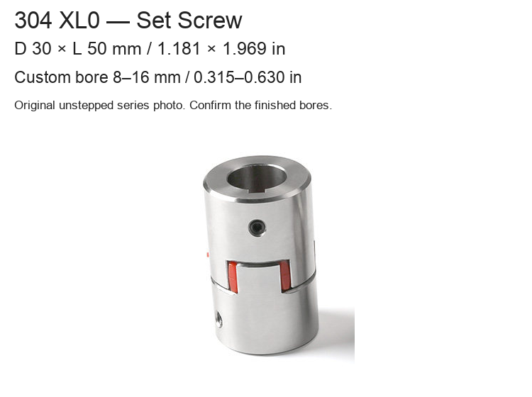
| XL0 Set Screw | 30 × 50 / 1.181 × 1.969 | 8–16 / 0.315–0.630 |
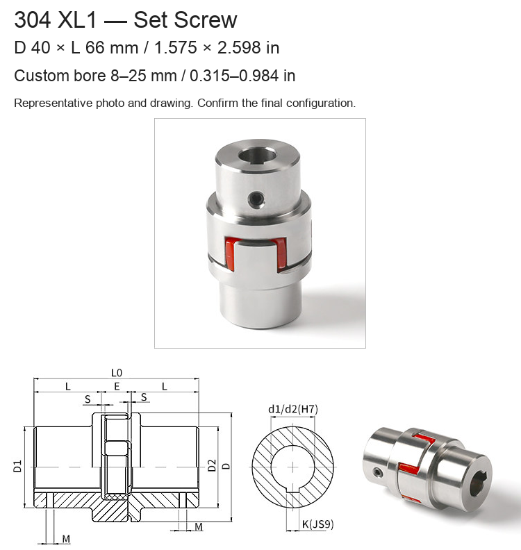
| XL1 Set Screw | 40 × 66 / 1.575 × 2.598 | 8–25 / 0.315–0.984 |
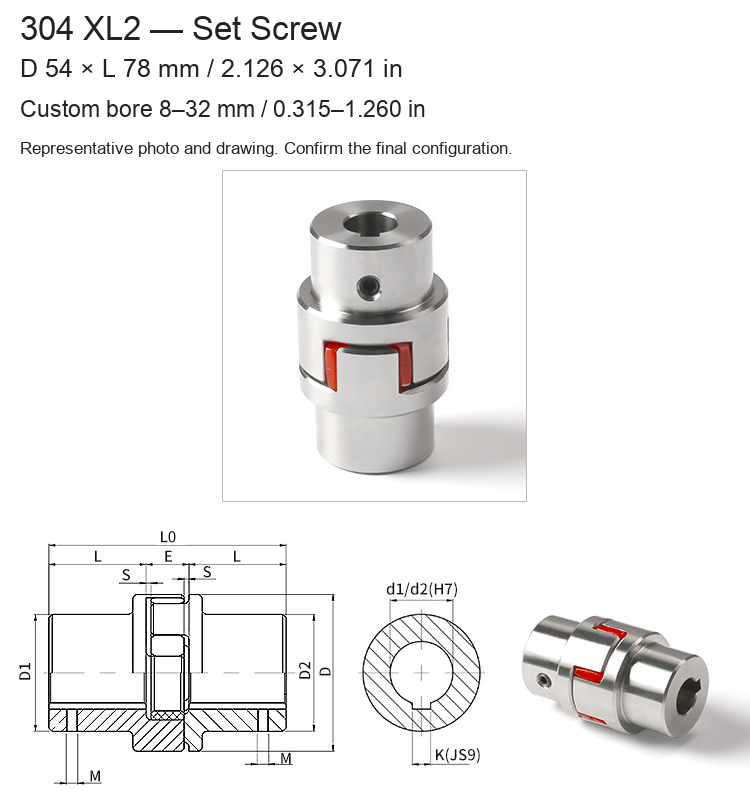
| XL2 Set Screw | 54 × 78 / 2.126 × 3.071 | 8–32 / 0.315–1.260 |
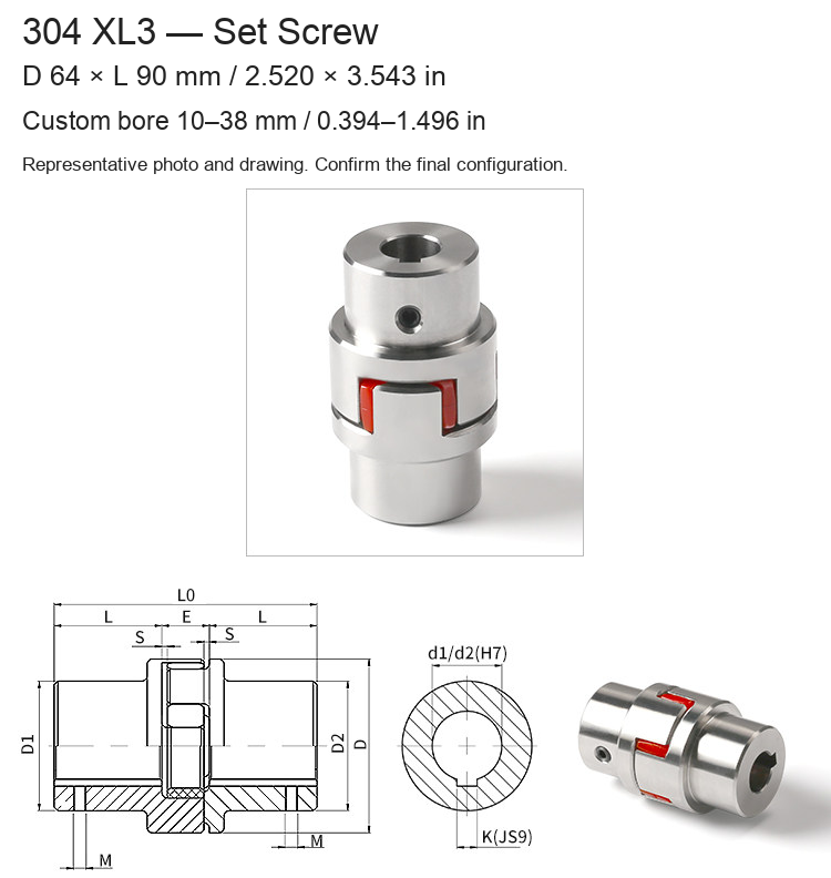
| XL3 Set Screw | 64 × 90 / 2.520 × 3.543 | 10–38 / 0.394–1.496 |
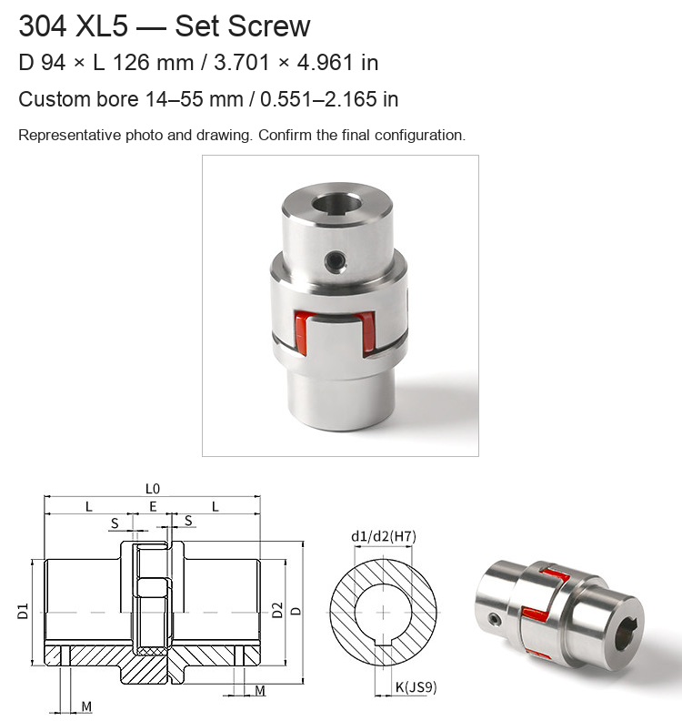
| XL5 Set Screw | 94 × 126 / 3.701 × 4.961 | 14–55 / 0.551–2.165 |
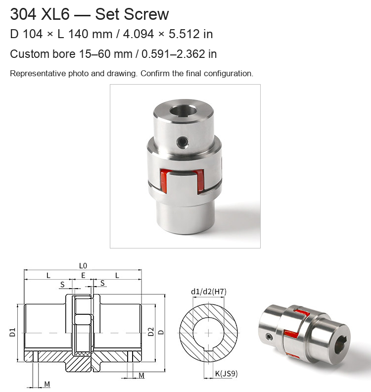
| XL6 Set Screw | 104 × 140 / 4.094 × 5.512 | 15–60 / 0.591–2.362 |
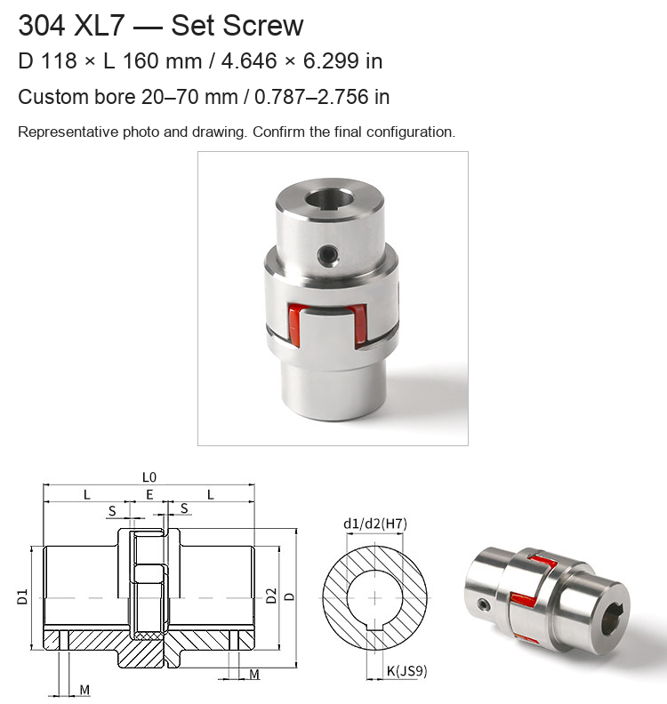
| XL7 Set Screw | 118 × 160 / 4.646 × 6.299 | 20–70 / 0.787–2.756 |
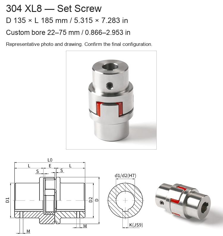
| XL8 Set Screw | 135 × 185 / 5.315 × 7.283 | 22–75 / 0.866–2.953 |
| XL9 Set Screw | 160 × 210 / 6.299 × 8.268 | 30–90 / 1.181–3.543 |
| XL10 Set Screw | 200 × 245 / 7.874 × 9.646 | 40–110 / 1.575–4.331 |
| XL0 Clamp | 30 × 50 / 1.181 × 1.969 | 8–14 / 0.315–0.551 |
| XL1 Clamp | 40 × 66 / 1.575 × 2.598 | 10–22 / 0.394–0.866 |
| XL2 Clamp | 54 × 78 / 2.126 × 3.071 | 8–28 / 0.315–1.102 |
| XL3 Clamp | 64 × 90 / 2.520 × 3.543 | 12–38 / 0.472–1.496 |
| XL4 Clamp | 78 × 114 / 3.071 × 4.488 | 12–45 / 0.472–1.772 |
| XL5 Clamp | 94 × 126 / 3.701 × 4.961 | 14–50 / 0.551–1.969 |
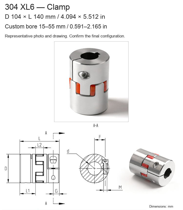
| XL6 Clamp | 104 × 140 / 4.094 × 5.512 | 15–55 / 0.591–2.165 |
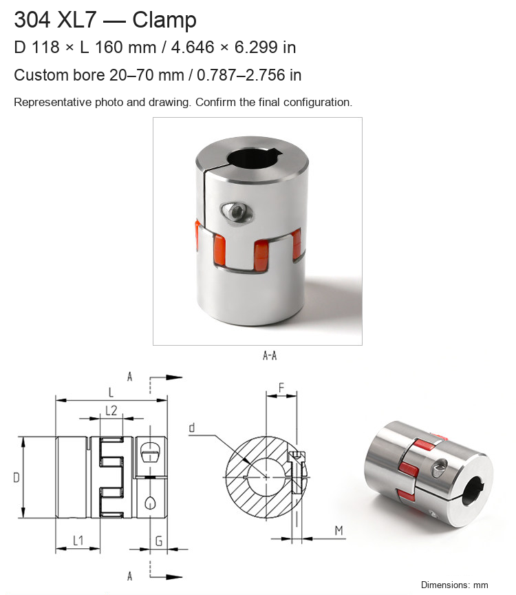
| XL7 Clamp | 118 × 160 / 4.646 × 6.299 | 20–70 / 0.787–2.756 |
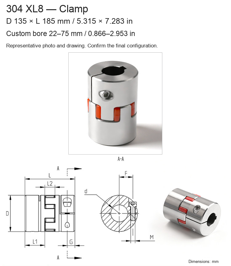
| XL8 Clamp | 135 × 185 / 5.315 × 7.283 | 22–75 / 0.866–2.953 |
| XL0 Split Clamp | 30 × 50 / 1.181 × 1.969 | 8–14 / 0.315–0.551 |
| XL1 Split Clamp | 40 × 66 / 1.575 × 2.598 | 10–22 / 0.394–0.866 |
| XL2 Split Clamp | 54 × 78 / 2.126 × 3.071 | 8–28 / 0.315–1.102 |
| XL3 Split Clamp | 64 × 90 / 2.520 × 3.543 | 12–38 / 0.472–1.496 |
| XL4 Split Clamp | 78 × 114 / 3.071 × 4.488 | 12–45 / 0.472–1.772 |
| XL5 Split Clamp | 94 × 126 / 3.701 × 4.961 | 14–50 / 0.551–1.969 |
| XL6 Split Clamp | 104 × 140 / 4.094 × 5.512 | 15–55 / 0.591–2.165 |
| XL7 Split Clamp | 118 × 160 / 4.646 × 6.299 | 20–70 / 0.787–2.756 |
Original Drawing and Reference Tables
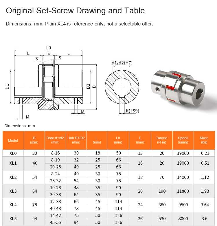
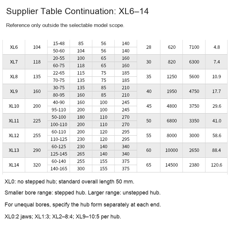
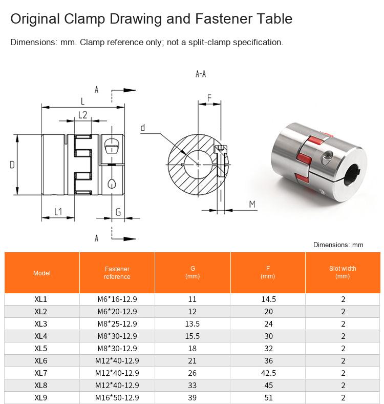
The set-screw drawing retains D, D1/D2, L/L0, gap E, set-screw M and the original bore/keyway notation. The clamp drawing retains G, F, L/L1/L2 and slot/fastener features. Original table numbers are retained as supplier references, including regular-hub nominal torque in N·m and speed in r/min. Regular/clamp figures are not a completed split-clamp drawing or an independent test certificate. Nonselectable rows are reference-only.
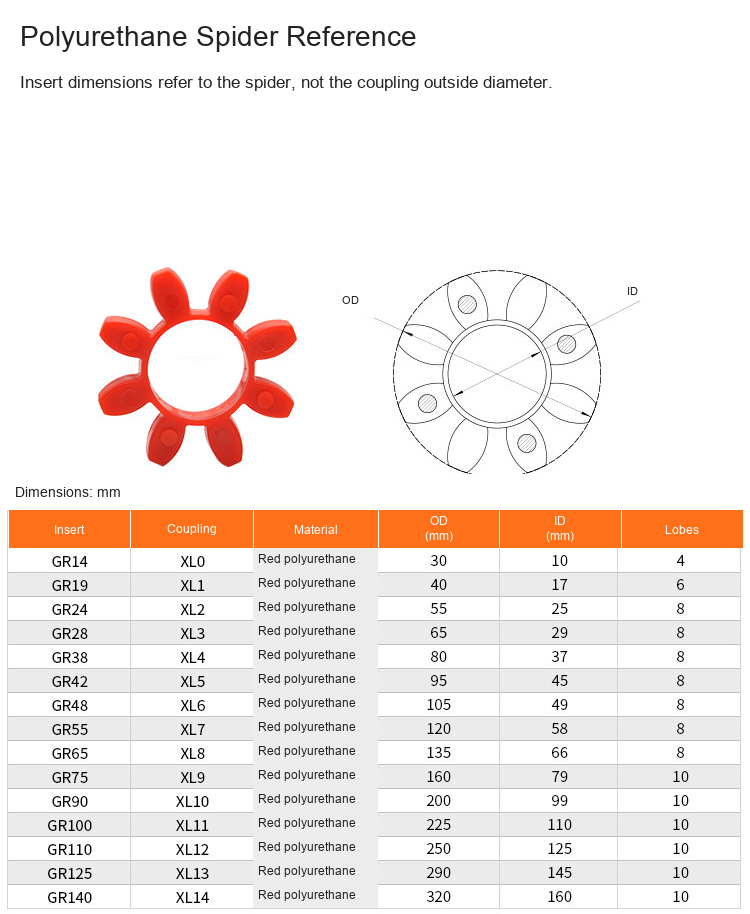
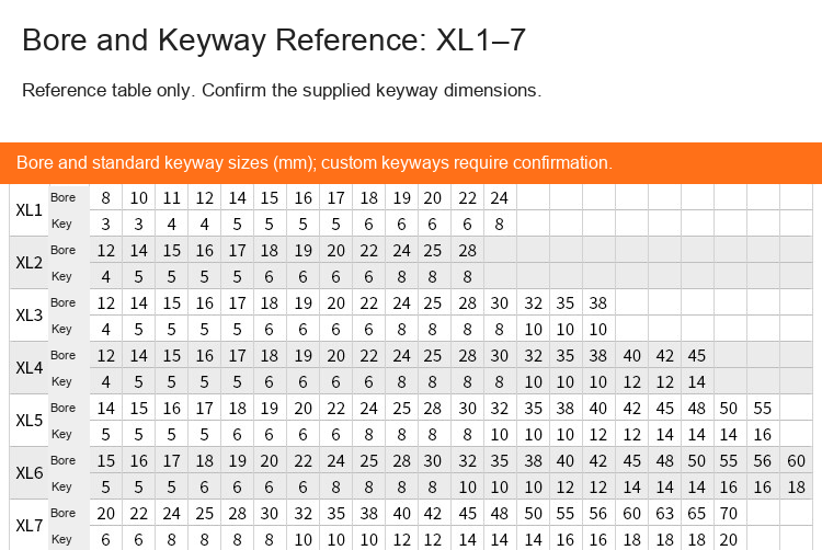
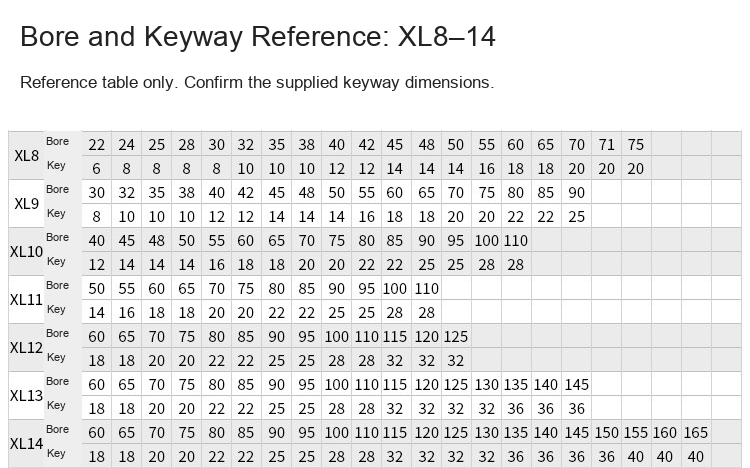
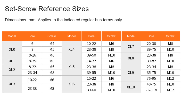
The source table indicates that the hub step depends on the bore. XL0 has no step and a standard overall length50 mm. The insert table gives spider OD/ID and lobe count, which are distinct from hub jaw count and coupling OD. Bore/keyway and set-screw tables apply only to their indicated reference configurations; confirm every selected shaft interface rather than assuming a pictured keyway is included or identical for every bore.
Installation and Inspection
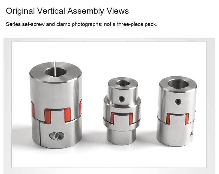
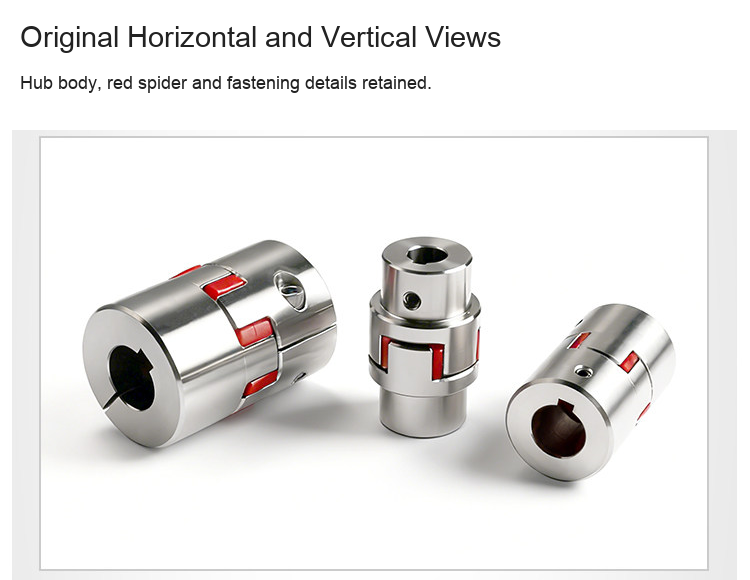
Check torque, speed, fits, alignment, installation space and the confirmed manufacturing drawing. Isolate equipment before fitting or servicing. Follow the assembly fastening and spider inspection/replacement instructions for the supplied coupling. Photos show original representative set-screw/clamp views, not exact custom bores or a multi-piece sales pack. No split-clamp photograph has been synthesized. Shafts and motors are not included.