28, 35 and 42 Series Hollow-Shaft Stepper Motors
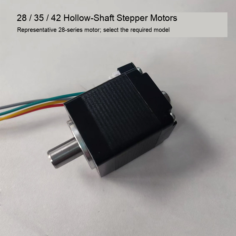
Standalone two-phase hollow-shaft stepper motors for vacuum pickup head and automation integration. Select the required motor series. Each option supplies one motor, not a complete placement head, vacuum nozzle, driver or vacuum-generator kit. Multiple orientations in a photograph do not establish a two-motor pack.
Source Specifications
| Series | Body length | Phase voltage | Phase current | Holding torque | Phase resistance | Inductance | Weight |
|---|---|---|---|---|---|---|---|
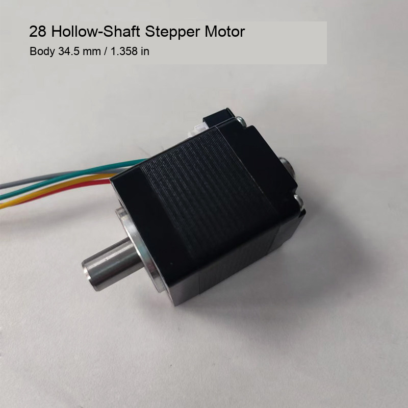
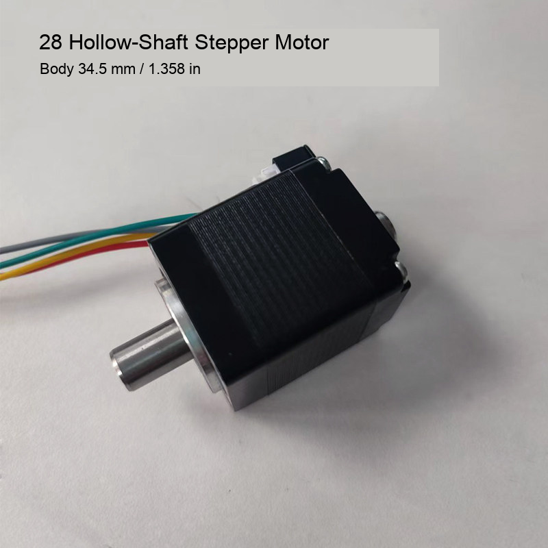
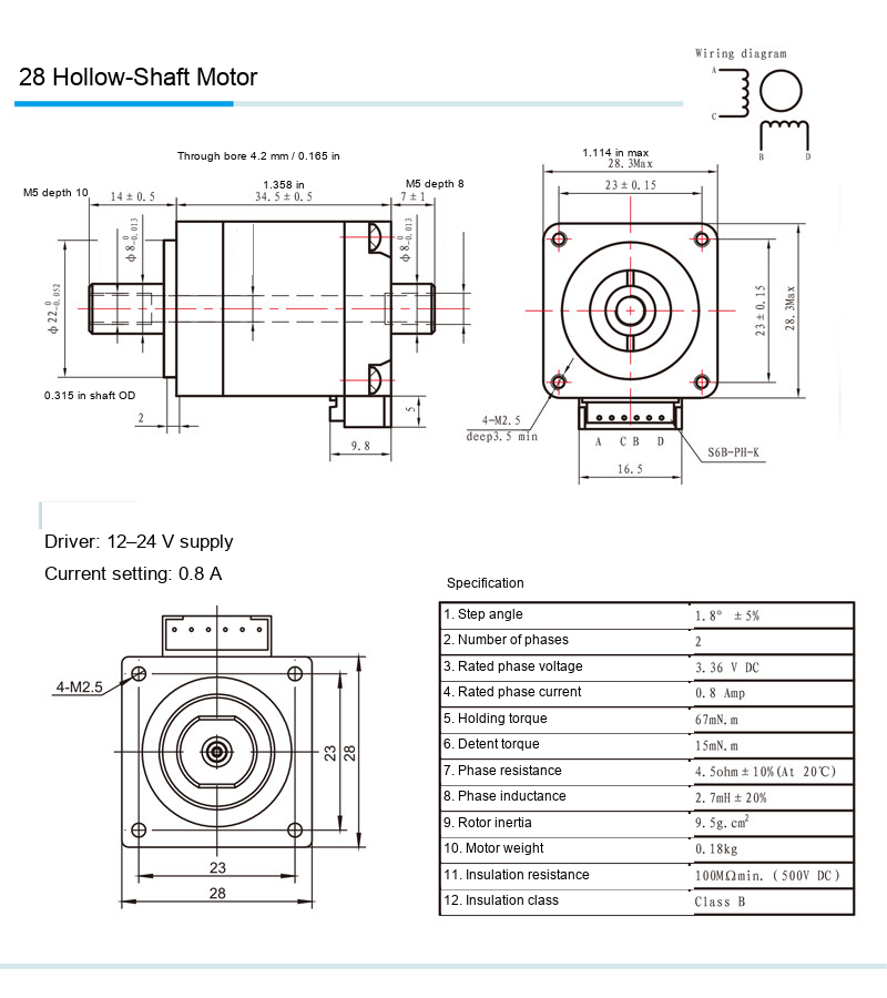
| 28 | 34.5 mm / 1.358 in | 3.36 V DC | 0.8 A | 0.067 N m | 4.5 ohm | 2.7 mH | 0.18 kg |
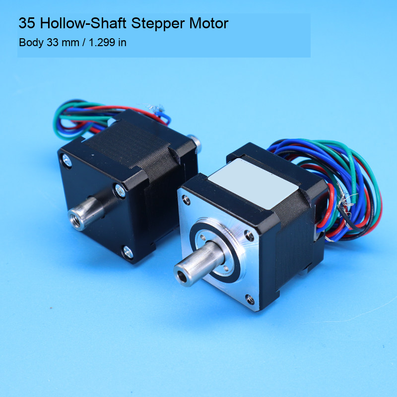
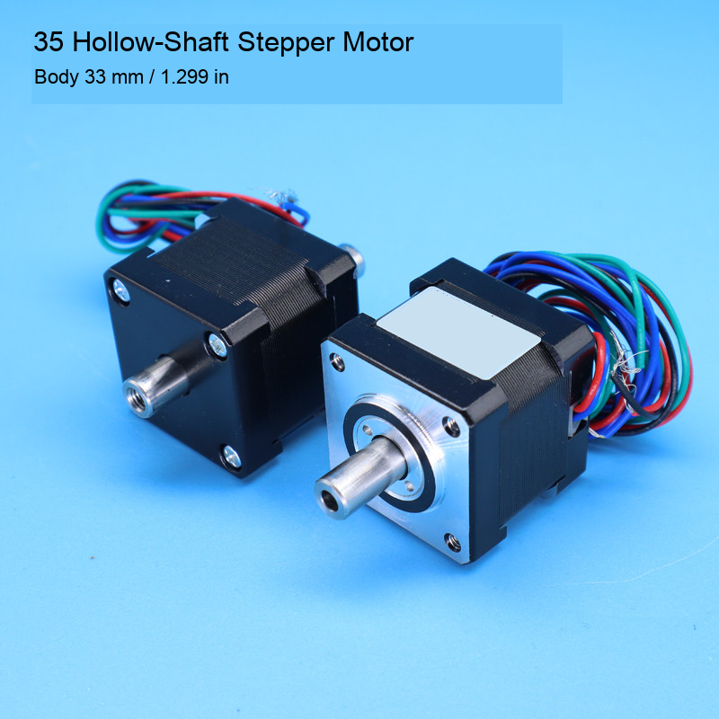
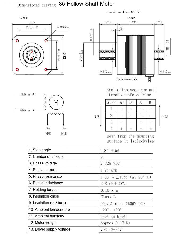
| 35 | 33 mm / 1.299 in | 2.325 V DC | 1.25 A | 0.16 N m | 1.86 ohm | 2.8 mH | 0.17 kg |
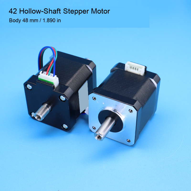
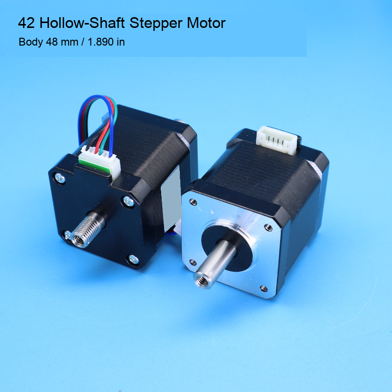
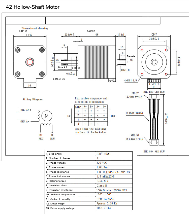
| 42 | 48 mm / 1.890 in | 3 V DC | 1.68 A | 0.55 N m | 1.8 ohm | 4.5 mH | 0.38 kg |
All three source sheets specify two phases, 1.8 degree step angle with ±5% tolerance, Class B insulation and minimum 100 megohm insulation resistance at 500 V DC. The supplier sheets are reproduced below. These are source specifications, not independent performance test results.
Mechanical Interfaces
The 28-series drawing gives a maximum 28.3 mm (1.114 in) frame, 34.5 ±0.5 mm (1.358 in nominal) body, 8 mm (0.315 in) shaft diameter and 4.2 mm (0.165 in) through bore. The 35-series drawing shows a 35 mm (1.378 in) frame, 33 ±1 mm (1.299 in nominal) body, 8 mm (0.315 in) shaft diameter and 4 mm (0.157 in) through bore. The 42-series drawing shows a 42 mm (1.654 in) frame, 48 mm (1.890 in) body, 8 mm (0.315 in) shaft diameter and 4.2 mm (0.165 in) through bore. Thread forms, end projections, mounting patterns and tolerances differ by model. Use the full original millimetre drawing to verify fit. Do not substitute a similar frame-size motor solely on its series number.
Driver and Wiring
Use a matched current-limited two-phase stepper driver. Rated phase voltage is not the driver supply voltage and does not mean that the motor should be connected directly to a power supply. The 28 and 35 source sheets list 12–24 V driver supply, and the 42 sheet lists 12–36 V. Source phase current is 0.8 A, 1.25 A and 1.68 A respectively. Confirm the driver current convention and wiring with the equipment specification. Follow the selected motor wiring diagram and verify phase pairing rather than assuming wire colors or connectors are universal.
Additional Source Data
The 28-series sheet lists 15 mN m detent torque, 4.5 ohm phase resistance ±10% at 20 degrees C, 2.7 mH inductance ±20% and 9.5 g cm squared rotor inertia. The 35-series sheet lists 1.86 ohm phase resistance ±10% at 20 degrees C and 2.8 mH inductance ±20%. The 42 sheet lists 1.8 ohm phase resistance ±10% at 20 degrees C and 4.5 mH inductance ±20%. The 35 and 42 sheets give an ambient range of -20 to +50 degrees C and 15% to 95% humidity. This humidity statement does not establish an ingress-protection rating or suitability for wet operation.
Installation and Scope
Disconnect power before wiring or changing the assembly. Confirm shaft clearance, mounting screws, end interfaces and the hollow vacuum passage. Check that the coupling does not impose excessive radial or axial load. Integrate the appropriate vacuum seals and fittings separately. Test direction, home position, movement and pickup on the actual equipment before production. No universal machine compatibility, rated speed, vacuum sealing performance or complete control system is supplied.
Original Motor Photos and Drawings
Product photographs and original dimension leaders are retained. Chinese labels are translated, supplier names are removed, and key dimension equivalents in inches are rounded to three decimal places. Series numbers identify the model family; use the exact drawing dimensions rather than treating the series number as an exact maximum frame measurement.
Modelo / configuración / SKU
| Modelo / configuración | SKU |
|---|---|
| 28 Series — Body 34.5 mm / 1.358 in | 4828107849590 |
| 35 Series — Body 33 mm / 1.299 in | 4828107849592 |
| 42 Series — Body 48 mm / 1.890 in | 4828107849591 |