


17-Series Automatic DC Bilge Pumps
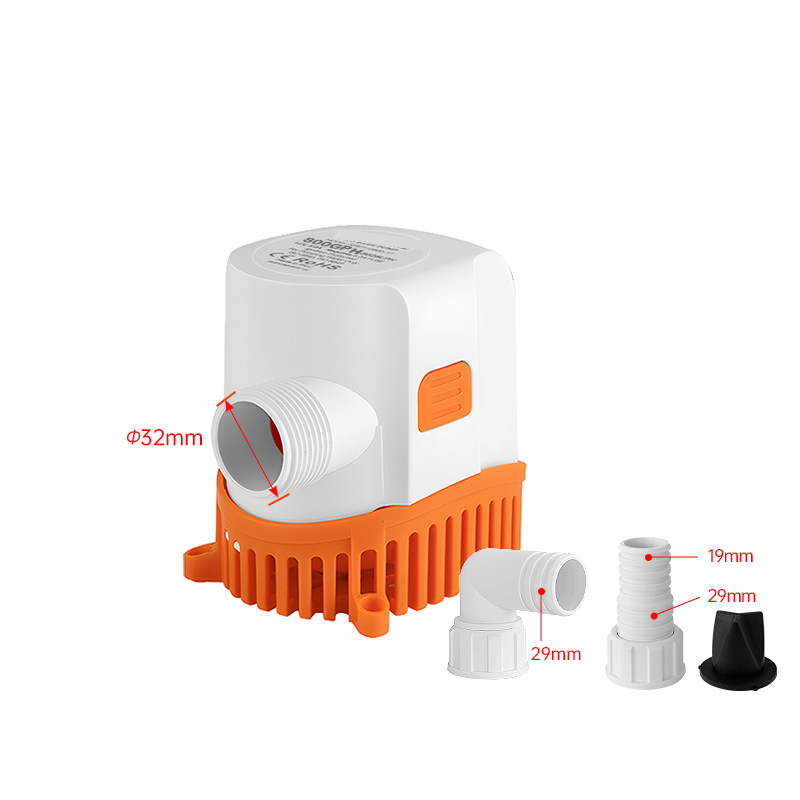
Submersible drainage pumps with an electronic water-level sensor, removable intake strainer and threaded outlet with the pictured hose adapters. Select the exact supply voltage and flow model. One selected pump and its pictured outlet accessories are supplied; the cover is an 800 GPH reference view, while each model button selects its own original photograph.
Available Models and Source References
| Selected model | Voltage | Nominal flow | Table current reference | Head reference |
|---|---|---|---|---|
| SFBP1-G800-17 | 12V DC | 800 GPH | 3.0 A | 2.5 m |
| SFBP1-G1200-17 | 12V DC | 1200 GPH | 4.0 A | 3.0 m |
| SFBP1-G2000-17 | 12V DC | 2000 GPH | 9.0 A | 4.0 m |
| SFBP2-G800-17 | 24V DC | 800 GPH | 1.5 A | 2.5 m |
| SFBP2-G1200-17 | 24V DC | 1200 GPH | 2.0 A | 3.0 m |
Flow, current and head above are source-table references, not a measured curve at every installation condition. The supplied material does not establish the test voltage, hose length or test method. Do not interpret maximum flow and head as simultaneous operating values, or the listed current as a fuse specification. Actual delivery changes with lift, hose diameter, length, bends and supply voltage. Confirm wiring and protection from the actual pump label and instructions.
Connections and Original Dimensions
| Model group | Housing reference | Pictured hose-barb references |
|---|---|---|
| 800 /1200 GPH | 128 x106 mm /5.039 x4.173 in | 800:19 /29 mm;1200:25 /29 mm |
| 2000 GPH | 148 x132 mm /5.827 x5.197 in | 29 mm /1.142 in |
The source photographs mark a 32 mm /1.260 in opening at the threaded outlet; this is not a hose-size or thread-standard guarantee. The 800 GPH accessory photo marks 19/29 mm barbs, the 1200 GPH photo marks 25/29 mm, and the 2000 GPH photo marks 29 mm. One source overview table instead prints 19 mm for the 12V 1200 model; this listing follows the model photograph and the dedicated adapter drawing, and makes that difference explicit. Confirm actual hose fit before ordering. The original nominal-inch markings and engineering lines remain visible. Added inch conversions use 25.4 mm per inch; the original metric references govern.
Automatic Operation and Maintenance
The source shows electronic sensing at the pump base: rising water starts the pump and falling water stops it. It also shows a Pump Check / Touch Here test label; keep that technical marking visible and use the test function according to the pump instructions. No separate external float switch is pictured for these options. The five-blade impeller and removable strainer are shown in the original internal views below. The one-way valve insert is intended to reduce reverse flow; it is not an independently verified anti-siphon device.
- Confirm voltage, model, hose routing and available mounting space. These DC models are voltage-specific; do not connect a 12V pump to a 24V supply.
- Secure the intake base on a suitable low, supported surface where water can reach the sensor and the intake remains clear. Check screw positions against the original drawing and the actual part.
- Fit the correct outlet adapter, seal and hose without stressing the housing. Support the hose, use compatible clamps and inspect the discharge route for kinks or restrictions.
- Connect according to the actual model wiring instructions, with suitable electrical protection and protected connections. The three-wire photograph illustrates available wiring arrangements; wire colours alone are not a complete wiring diagram.
- Test automatic start/stop and discharge under supervision. Isolate electrical power before removing the strainer, inspecting the impeller or cleaning debris.
Scope and Ordering Notes
These are bilge-drainage pumps, not documented drinking-water supply pumps or fuel-transfer pumps. No certification, ignition-protection rating, seawater service life or dry-running duration is promised from the supplied material. Maintain the vessel's required drainage arrangements and follow its installation and operating instructions. The 1500 GPH variants and 24V 2000 GPH variant are excluded pending resolution of conflicting source head/current tables. A different model must not be substituted merely because its housing looks similar.
Product photographs, sensor operation, discharge, internal impeller, valve, cleaning and original mounting/adapter drawings are retained below. Contact boltte@boltte.com for model-specific wiring or performance confirmation before purchase.


Modelo / configuración / SKU
| Modelo / configuración | SKU |
|---|---|
| 12V DC / SFBP1-G800-17 / 800 GPH | 5770867853485 |
| 12V DC / SFBP1-G1200-17 / 1200 GPH | 5938347667128 |
| 12V DC / SFBP1-G2000-17 / 2000 GPH | 5938347667124 |
| 24V DC / SFBP2-G800-17 / 800 GPH | 5938347667127 |
| 24V DC / SFBP2-G1200-17 / 1200 GPH | 5938347667129 |