Cylinder speed depends on controlled airflow and load behavior, not merely the regulator setting. Meter-in and meter-out flow controllers act in different directions. Identify the selected valve's circuit symbol before changing an existing machine or buying a visually similar replacement.
1. Identify the controlled direction
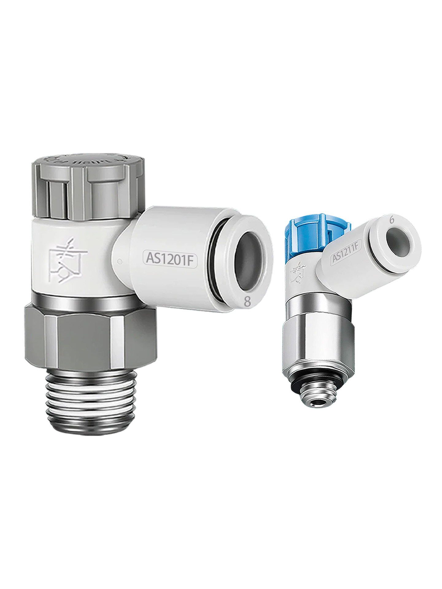
Meter-in controls air entering the actuator; meter-out controls exhaust leaving it. A flow-control assembly may include a reverse-flow path, so the arrow and pneumatic symbol matter more than the knob's appearance.
SMC cylinder instructions describe meter-out for many double-acting cylinder applications. That general principle is not permission to redesign every circuit, especially one with gravity-driven or overrunning loads.
2. Describe the actuator and load
Record cylinder type, stroke, mounting orientation, moving mass and the required travel time in both directions. Note whether gravity or another mechanism assists one direction. Pneumatic compressibility and changing load can make a setup behave differently near the ends of travel.
Keep cushioning and end-stop adjustment separate from mid-stroke speed control. A slower command does not establish that impact energy is within the machine's limits.
3. Read the complete AS selection
The linked AS range includes elbow, inline and selected specialty configurations. Match tube outside diameter, port thread, controlled direction and locking arrangement. Some selector images contain only a model label; request missing dimensional or functional information before purchase.
Do not combine a drawing from one AS code with another code's thread size. Confirm installation space and access to the adjustment after the valve is mounted.
4. Check installation before adjustment
Trace the ports using the approved circuit drawing and confirm the intended flow path. Inspect tubes for damage and verify that fittings are fully installed according to their instructions. Isolate pressure before replacing or reversing a valve.
A flow controller is not a load-holding device. Support the mechanism and retain the machine's approved safeguards throughout commissioning and maintenance.
5. Adjust and measure systematically
Follow the equipment procedure for the initial setting and permitted adjustment range. Change one direction at a time, measure travel time and observe smoothness under the real load. Do not open a restriction abruptly while personnel are near the mechanism.
Check both loaded and unloaded cycles where the machine procedure requires them. Record the accepted setting and use the specified lock feature rather than assuming the knob cannot drift.
6. Troubleshoot without confusing pressure and flow
If motion remains inconsistent, inspect supply stability, cylinder condition, exhaust restrictions and mechanical binding. Increasing pressure or changing to a larger valve may conceal the cause rather than solve it.
Send the circuit symbol, cylinder data and travel-time measurements with a replacement inquiry. Specify meter-in or meter-out explicitly, together with the full model code and connection dimensions.
7. Related products and next steps
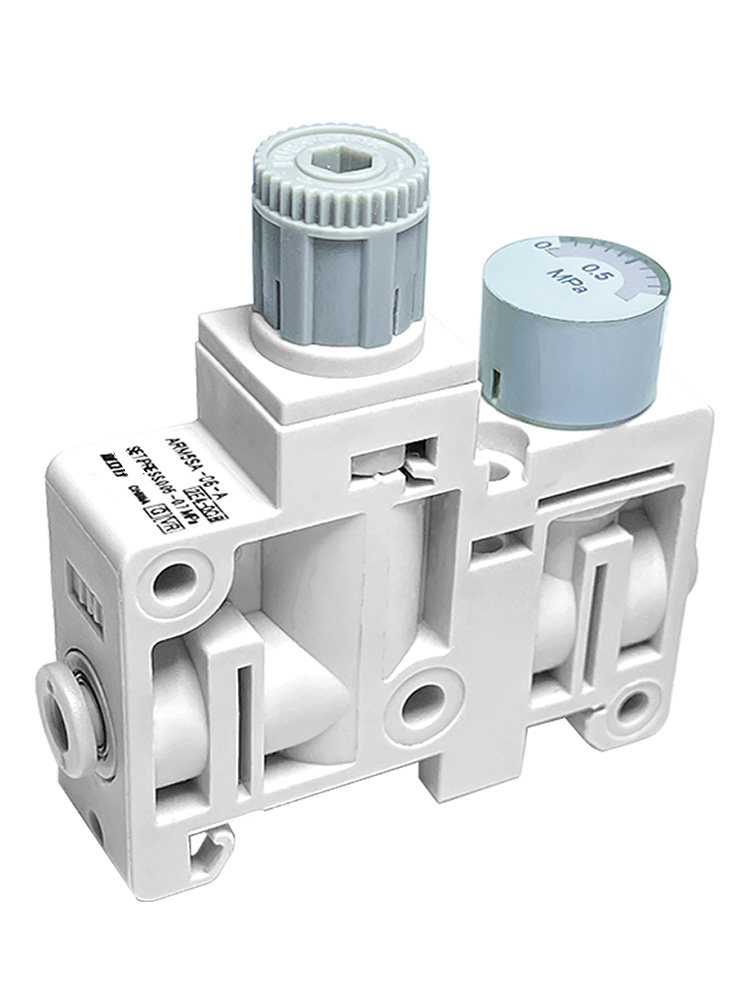
AS flow controllers · Pressure regulators.
Send the complete model code, drawings or photographs, required quantity and application conditions to boltte@boltte.com. Confirm missing specifications in writing before ordering. Catalogue images illustrate the linked product family; they are not proof of compatibility, tested capacity or certification for your installation.
8. Further technical reading
These manufacturer references explain general engineering principles. Their product ratings, test results and installation values do not apply automatically to BOLTTE selections.