THIRD-PARTY REPLACEMENT
Compatible with the listed SMC models. Not an original/OEM SMC product. Model references are for compatibility identification only.
Quick Selection Guide for ZP3-Y (UMS / UMN, B5/B5)
Goal: help you pick the right cup size quickly by surface, required load, and working mode.
Step 1 — Surface and environment check (mandatory before choosing size)
Surface allow list
- Recommended: glass, polished aluminum, polished steel, smooth painted rigid metals
- Typical: hard ABS/PC/PMMA, PVC/PP/PE with stable flat contact
- Use only after trial if slightly textured: rigid engineering plastics with good finish
Do not select until corrected:
- Porous / woven / rough / open-cell surfaces
- Wet, oily, dusty, dusty-porous, or condensation-prone surfaces
- Cracked, chipped, soft foam, warped or concave surfaces at contact points
Step 2 — Load mode
- Static mode: no acceleration at the gripped object, low-frequency motion
- Dynamic mode: robot or linear acceleration, frequent start/stop, short transport distance
- Vibration mode: shaker, high-frequency equipment vibration, uneven stop-start impact
Step 3 — Choose diameter / number of cups
Estimation method (engineering only, not a certified lifting value)
- Formula: suction force F = P × A
- 10 kPa and 13 kPa are used for comparison only
- Recommended safe load = 50% F for static, 25% F for dynamic/vibration
- Total recommended payload = Σ(single-cup safe load) × system margin (0.9 static, 0.8 dynamic)
| Diameter | Area A (mm²) | Single-cup theoretical max 10 kPa / 13 kPa | Safe / cup (Static) | Safe / cup (Dynamic) |
|---|---|---|---|---|
| 4 mm | 12.57 | 12.8 g / 16.6 g | 6.4 g / 8.3 g | 3.2 g / 4.1 g |
| 6 mm | 28.27 | 28.8 g / 37.4 g | 14.4 g / 18.7 g | 7.2 g / 9.4 g |
| 8 mm | 50.27 | 51.2 g / 66.6 g | 25.6 g / 33.3 g | 12.8 g / 16.6 g |
| 10 mm | 78.54 | 80.0 g / 104.0 g | 40.0 g / 52.0 g | 20.0 g / 26.0 g |
| 13 mm | 132.73 | 135.0 g / 175.5 g | 67.5 g / 87.8 g | 33.8 g / 43.9 g |
| 16 mm | 201.06 | 205.0 g / 266.5 g | 102.5 g / 133.2 g | 51.3 g / 66.6 g |
Estimated vs tested value policy
All numbers above are engineering estimates from geometry + vacuum level. For production use, always add a customer test:
- Use your real object, real mounting bracket, and real vacuum line
- Record suction/vent time and holding drift
- If any test result is below the estimated static value, scale model or reduce cycle speed and re-test
Minimum validation parameters before bulk use
- Single piece mass
- Number and distribution of contact points on the part
- Vacuum pressure setting and valve response time
- Static vs dynamic ratio of movement, and vibration level
- Surface cleanliness class (dry / dry+dusted / oily+wet)
3-step acceptance SOP (recommended)
- Cycle 1: 3 repeated pick attempts, observe attach stability and whether first vacuum holds.
- Cycle 2: Hold for 10 s at max target load and check for leak-down or drift.
- Cycle 3: 10-cycle repeat test with full sequence timing; target: no earlier-than-expected release and no cup slip.
Boundary and derating
| Use case | Recommended margin | Remark |
|---|---|---|
| Static holding | Base safe values | Validate by 10-s hold test first |
| Dynamic transport | 50% additional margin | Use 25% of theoretical per-cup values in planning |
| Long continuous operation | Extra 20%–30% derating | Run leak test every 24–72 hours |
| Vibration | Use <= 25% of theoretical planning value | Do not rely on single-pass calculations |
Operating boundary (practical)
- Humidity: keep environment below condensation risk; avoid direct moisture films on contact face
- Temperature: follow your system-specific cup-material limit; keep near catalog limits and test at the lowest temperature point
- Chemical media: avoid strong solvents, fuel/oil mist, strong acid/alkali, oxidizers and corrosive rinse fluids near seal area
Model index (exact code)
UMS
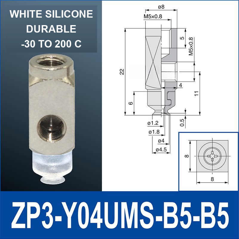
- 4 mm: ZP3-Y04UMS-B5-B5
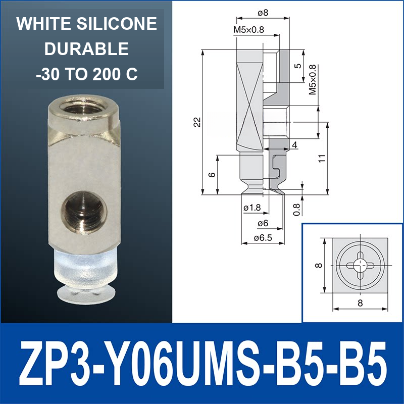
- 6 mm: ZP3-Y06UMS-B5-B5
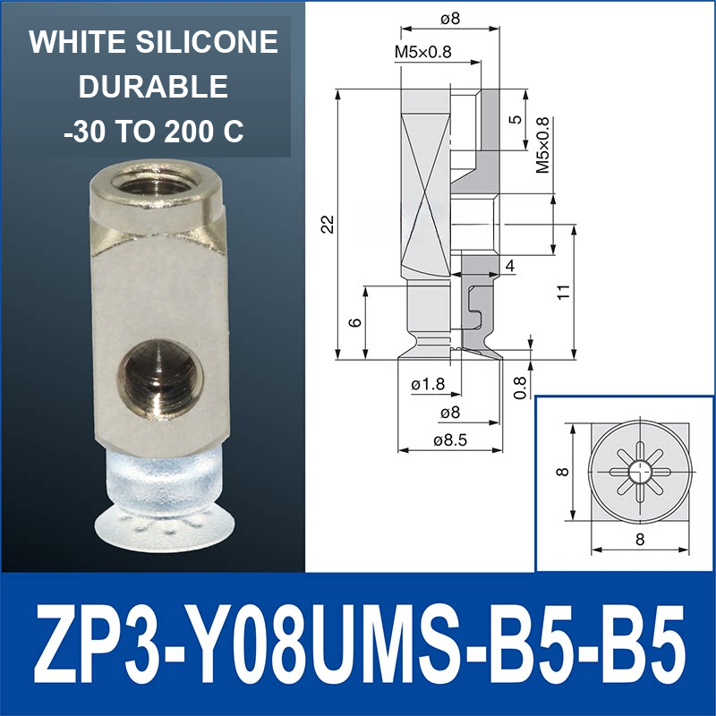
- 8 mm: ZP3-Y08UMS-B5-B5
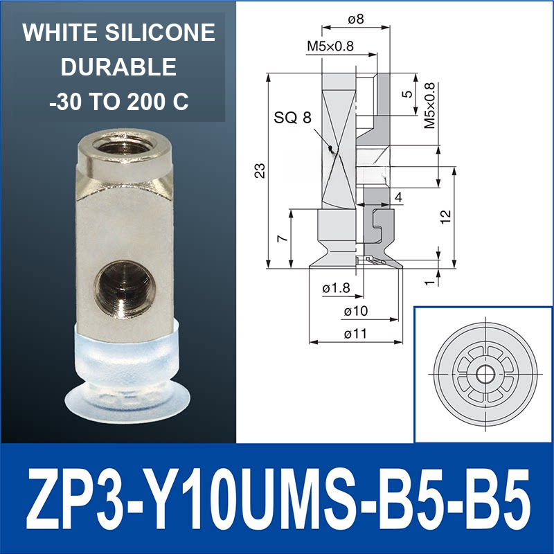
- 10 mm: ZP3-Y10UMS-B5-B5
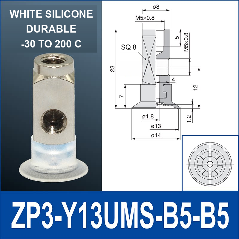
- 13 mm: ZP3-Y13UMS-B5-B5
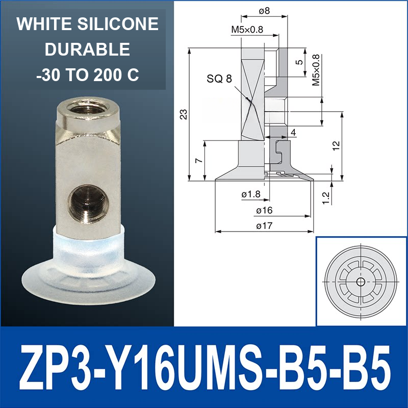
- 16 mm: ZP3-Y16UMS-B5-B5
UMN
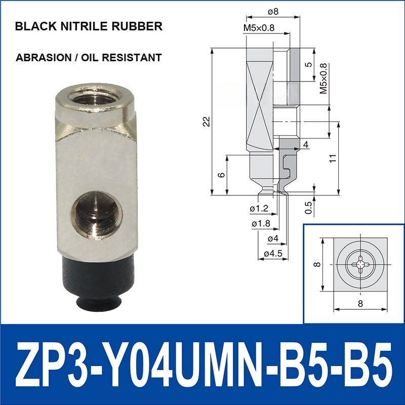
- 4 mm: ZP3-Y04UMN-B5-B5
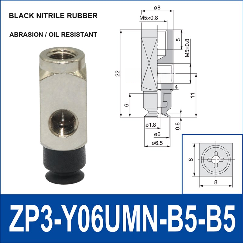
- 6 mm: ZP3-Y06UMN-B5-B5
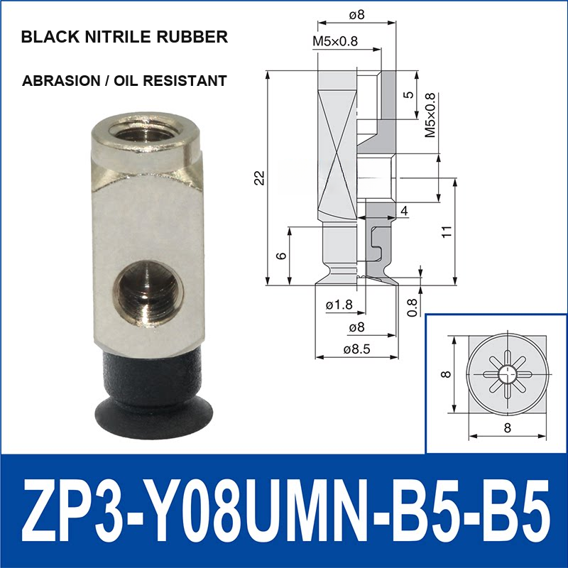
- 8 mm: ZP3-Y08UMN-B5-B5
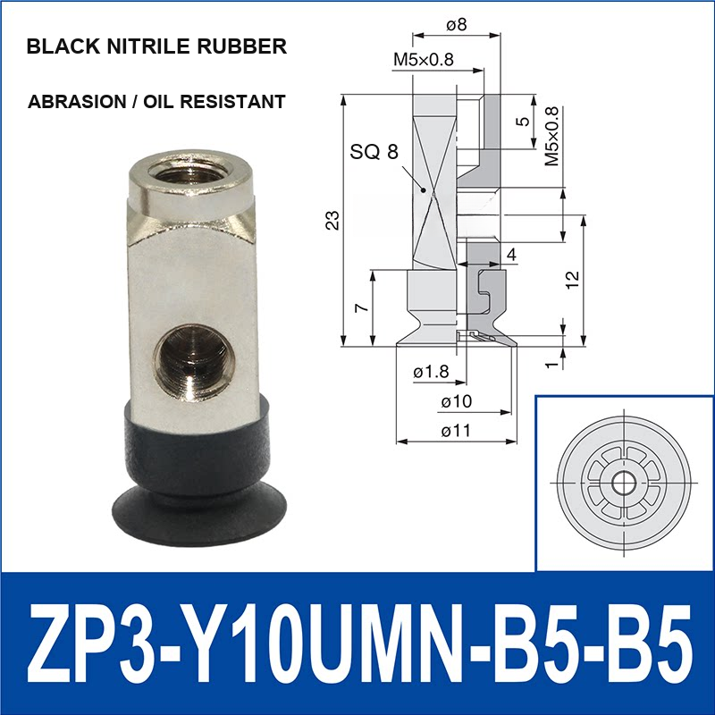
- 10 mm: ZP3-Y10UMN-B5-B5
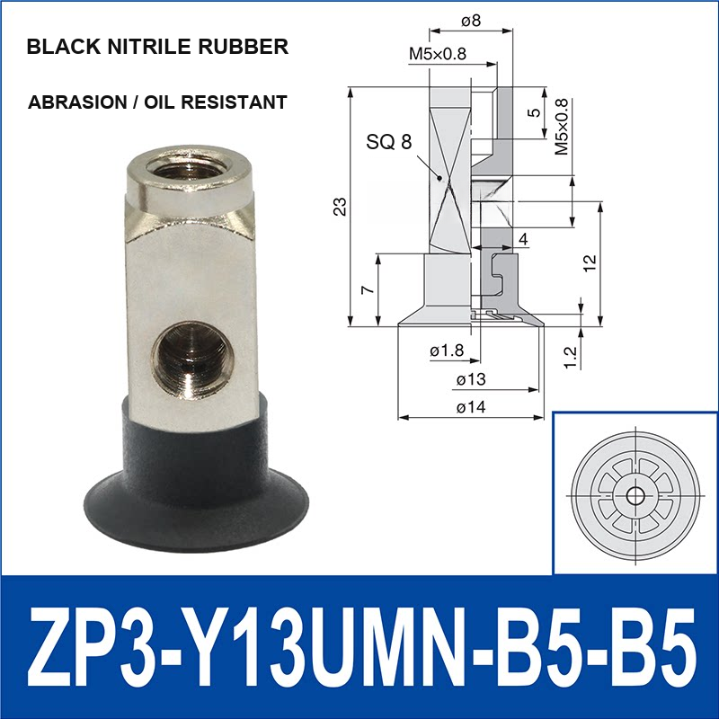
- 13 mm: ZP3-Y13UMN-B5-B5
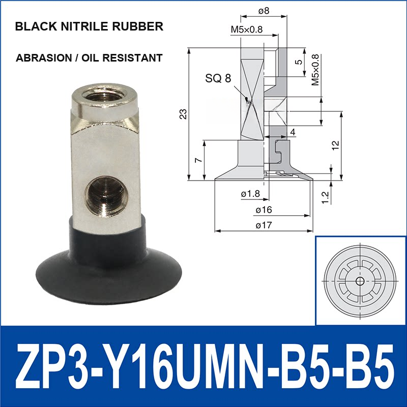
- 16 mm: ZP3-Y16UMN-B5-B5
Safety use: not for direct human-safety lifting certification. If surface, speed, or environment is uncertain, request a pre-production test plan before mass order.