PC Two-Way Control Valves, G1/8 to 6.0 mm Connection
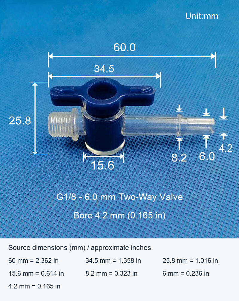
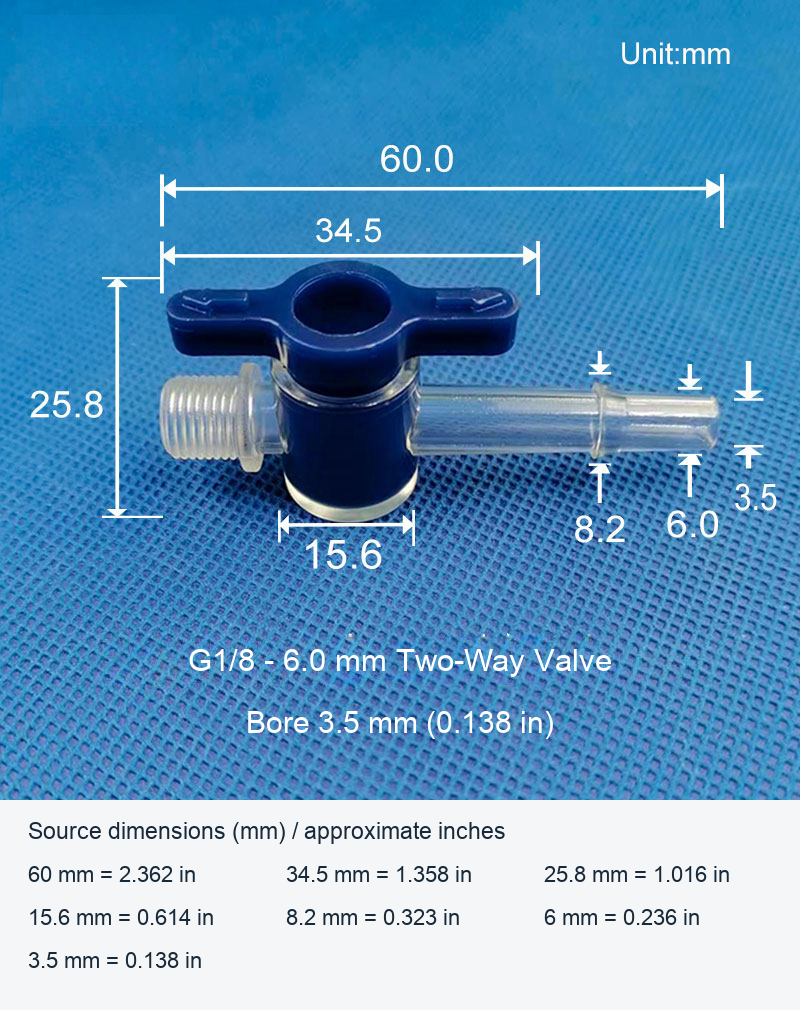
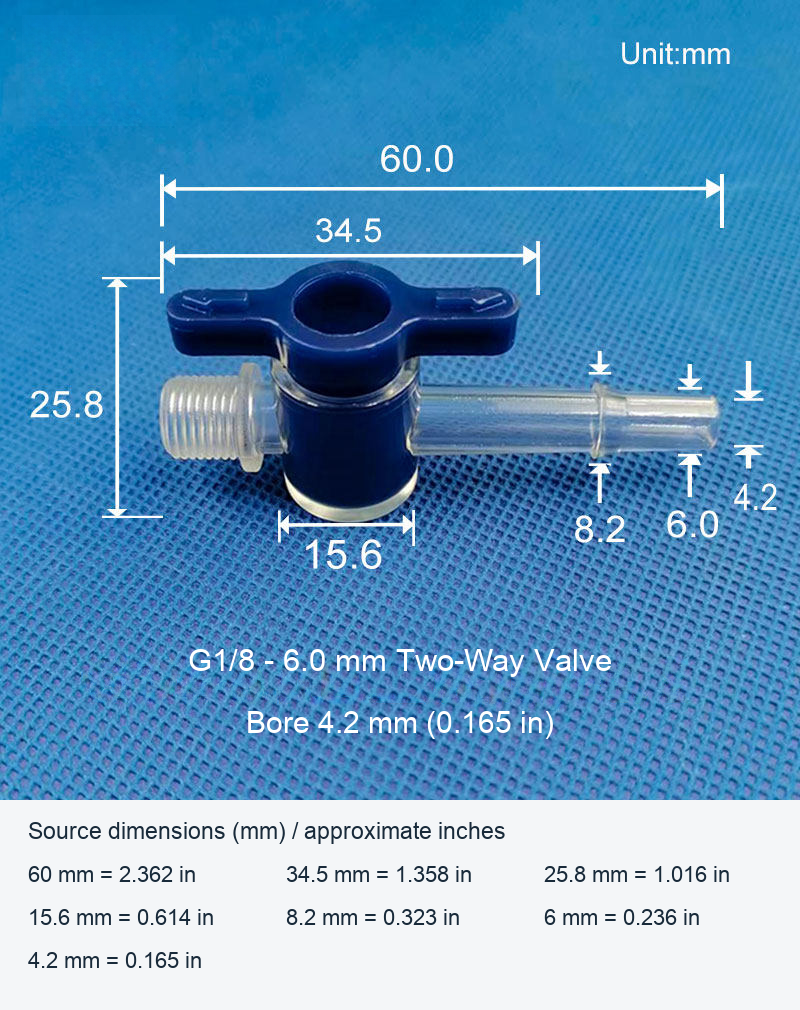
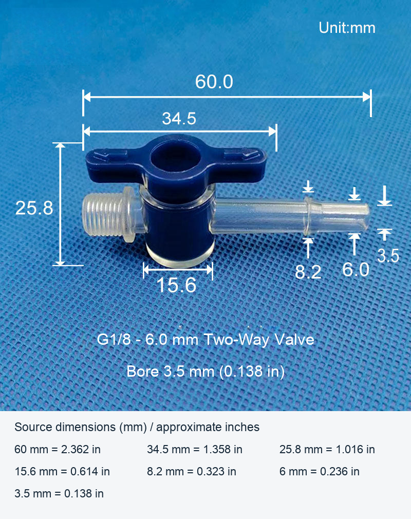
Compact manually operated two-way plastic valves with a blue handle, one male G1/8 threaded end and one hose connection end designated 6.0 mm in the supplied drawings. Choose a 4.2 mm or 3.5 mm passage option. Both options have the same external dimensions shown below.
Available Passage Options
| Model | Passage diameter | Threaded end | Hose end |
|---|---|---|---|
| G1/8 - 6.0 mm / Bore 4.2 mm | 4.2 mm (0.165 in) | G1/8 male thread | 6.0 mm source designation |
| G1/8 - 6.0 mm / Bore 3.5 mm | 3.5 mm (0.138 in) | G1/8 male thread | 6.0 mm source designation |
Dimensions and Material
| Body material | Polycarbonate (PC), as specified in the selected source options |
|---|---|
| Overall length shown | 60.0 mm (2.362 in) |
| Overall height shown | 25.8 mm (1.016 in) |
| Handle span shown | 34.5 mm (1.358 in) |
| Body width shown | 15.6 mm (0.614 in) |
| Additional hose-end dimension shown | 8.2 mm (0.323 in) |
Thread and Hose Selection
G1/8 is a nominal thread specification, not a 1/8-inch measured outside diameter. The 6.0 mm connector designation is separate from the 4.2 mm or 3.5 mm passage diameter and from the other end dimensions on the drawing. Check the mating thread, sealing arrangement and actual hose fit before installation. Do not interchange the two passage options solely because their exterior appearance is the same.
Operation and Application Checks
Select the required passage diameter for the assembly and operate the handle without excessive force. Verify the open and closed positions, connection retention and sealing with the actual setup. Working pressure, temperature limits, fluid compatibility, seal composition and tested leakage performance are not specified in the supplied data. No syringe, tubing, adapters or other accessories pictured in supplier application examples are included in these selected valve options.
Original Views and Model-Specific Drawings
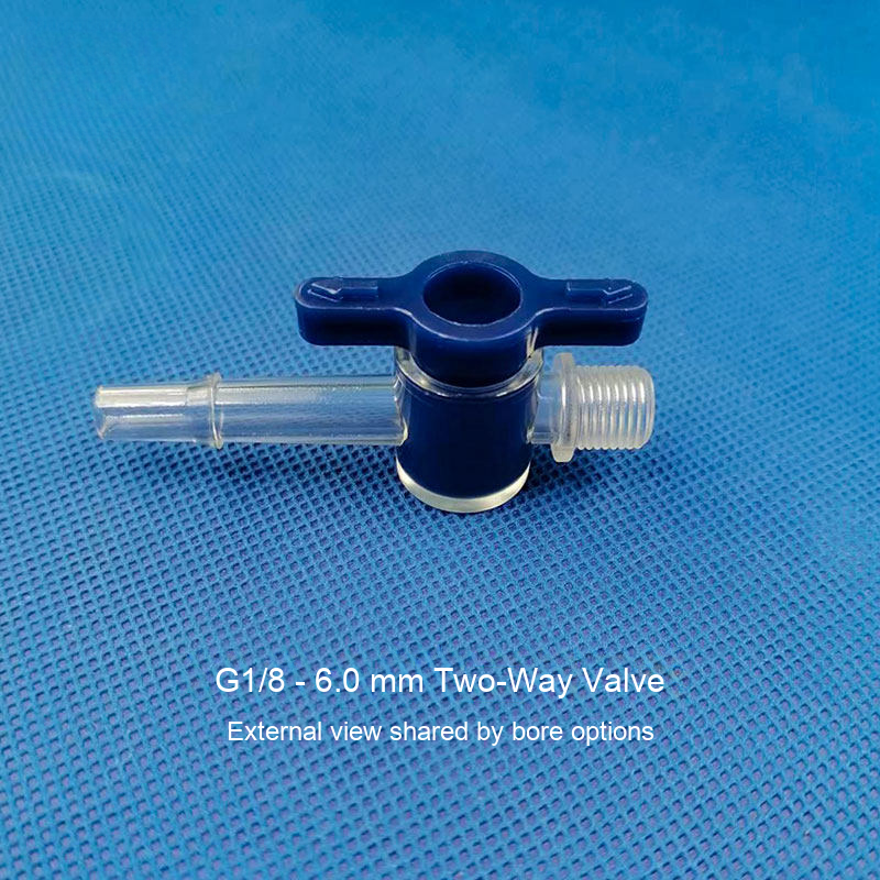
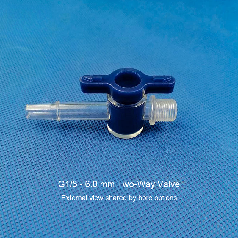
The first two images are the original model-specific drawings, retaining all product pixels, metric measurements, arrows and dimension lines. Supplier logos and Chinese captions have been removed only from the empty background and translated. Approximate inch conversions are rounded to three decimal places. The final original photograph shows the shared exterior of the G1/8 - 6.0 mm body and does not distinguish the internal passage options. Use the labelled model drawing and selected option for the bore size.
Model / configuration / SKU
| Model / configuration | SKU |
|---|---|
| G1/8 - 6.0 mm / Bore 4.2 mm | 4907515772531 |
| G1/8 - 6.0 mm / Bore 3.5 mm | 5786324251932 |