A replacement jaw changes the tool's contact geometry even when it bolts onto the same gripper. Match the original interface, opening behavior and workpiece requirements. Distinguish spare jaws from complete grippers before preparing an order or commissioning a repaired end-effector.
1. Capture the existing configuration
Photograph the assembled tool and each jaw before removal. Record gripper model, jaw markings, mounting hole positions and the orientation of left and right pieces. Note whether the original selection is a pair or a single component.
Keep any locating features in the record. Matching screw spacing alone does not prove that the jaw seats or aligns correctly.
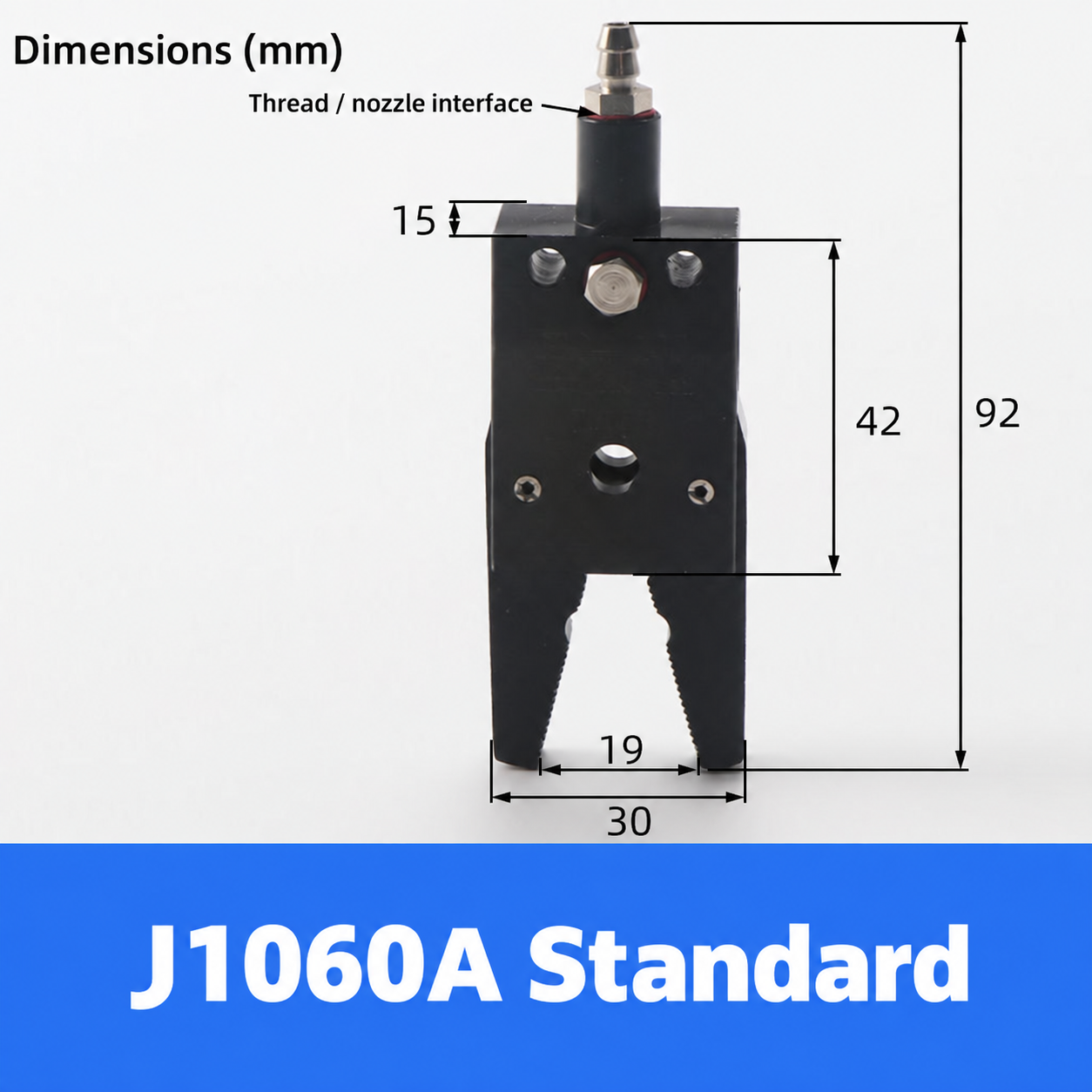
2. Check the complete model family
The J1060/E/F/H and CH1410 catalogues contain multiple mechanism and jaw selections. Confirm which option is a complete unit and which is a replacement component. Do not combine codes from different families based on a similar outline.
If a drawing is incomplete, send measurements and request confirmation before purchase. Preserve uncertainty rather than filling a missing dimension from another option.
3. Review the workpiece contact
Identify the intended gripping surface and acceptable marking, deformation or slip. Check pad attachment, contact area and access around the part. A longer or differently shaped jaw may reach the part while altering the forces and moments seen by the gripper.
Ask for application review when changing geometry or material. A direct maintenance replacement and a new custom finger design are different scopes.
4. Inspect the mechanism as well as the jaw
Look for damaged threads, loose locating features, wear or contamination using the machine's service procedure. A new jaw will not correct a faulty mechanism or an incorrect actuation sequence.
Isolate energy before disassembly and support anything held by the tool. Use the exact mounting hardware and tightening instructions rather than reusing an unverified substitute.
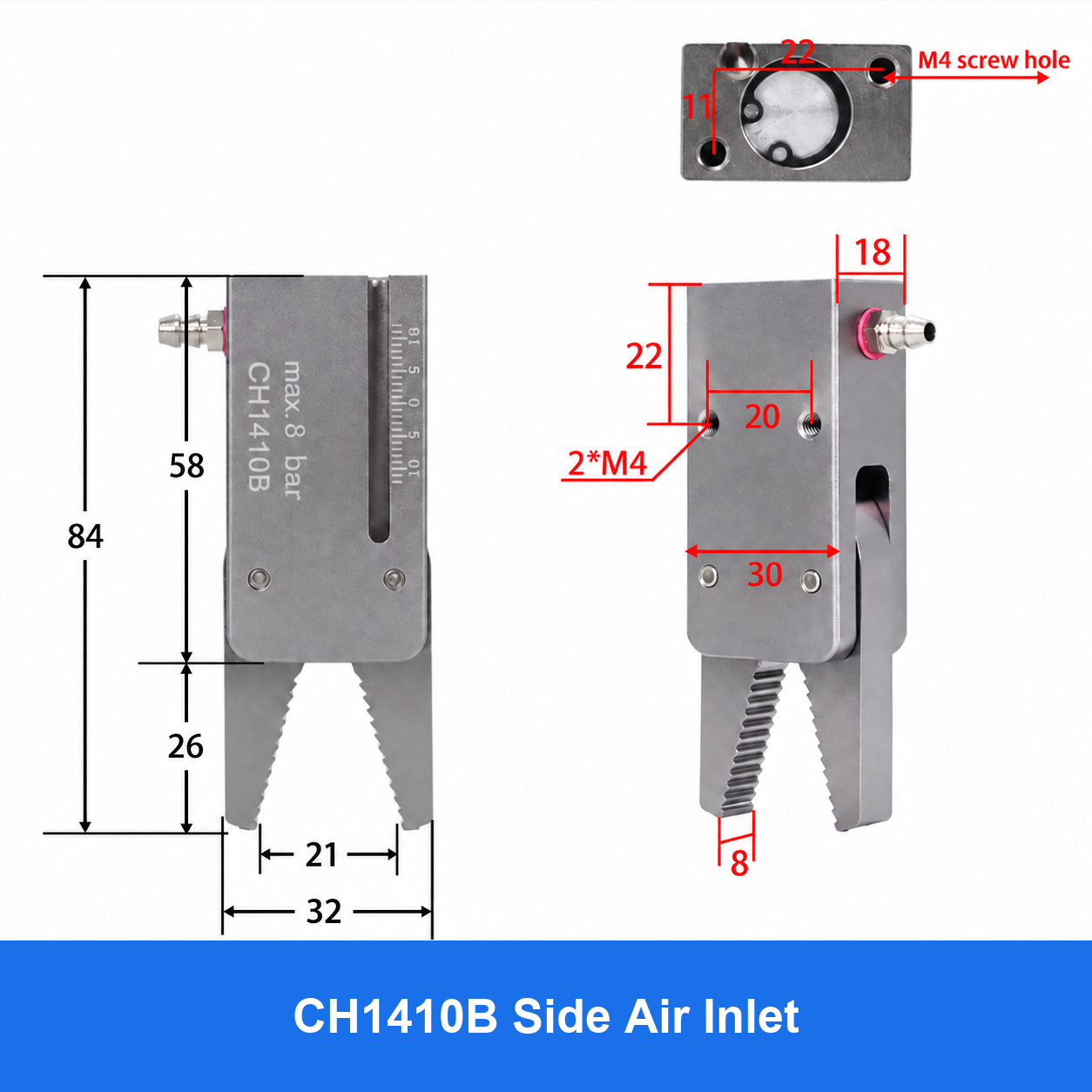
5. Check travel and release
Commission with representative parts in a guarded setup. Verify opening clearance, contact position, approach path and clean release. Confirm that sensors and the controller recognize the actual new configuration where applicable.
Do not assume that an unchanged closed position proves the whole stroke is safe. Watch for interference throughout travel and during tool changes.
6. Make the spare unambiguous
Order by complete jaw code, mating gripper, side or pair requirement, material and any pad or finger detail. Attach the accepted drawing or photograph with orientation labels.
Retain the original and replacement references in the machine file, plus the acceptance result. If compatibility remains uncertain, request a matched assembly review rather than describing the spare simply as a mini robot jaw.
7. Related products and next steps
J1060/E/F/H catalogue · CH1410 catalogue.
Send the complete model code, drawings or photographs, required quantity and application conditions to boltte@boltte.com. Confirm missing specifications in writing before ordering. Catalogue images illustrate the linked product family; they are not proof of compatibility, tested capacity or certification for your installation.