Adjustable rods and brackets help position cups and grippers, but adjustment range alone does not establish a stable tool. Review the entire fixture layout, fastening and motion envelope. Keep positioning hardware separate from the gripper or cup's own performance requirements.
1. Draw the tool layout first
Show the robot interface, rods, brackets, contact devices and workpiece. Mark each adjustable joint and the intended contact points. Record overall mass and offsets for the robot's payload review.
Include the fully extended and contracted positions. A convenient bench arrangement may place components or hoses outside the permitted envelope when mounted on the machine.
2. Match every mechanical interface
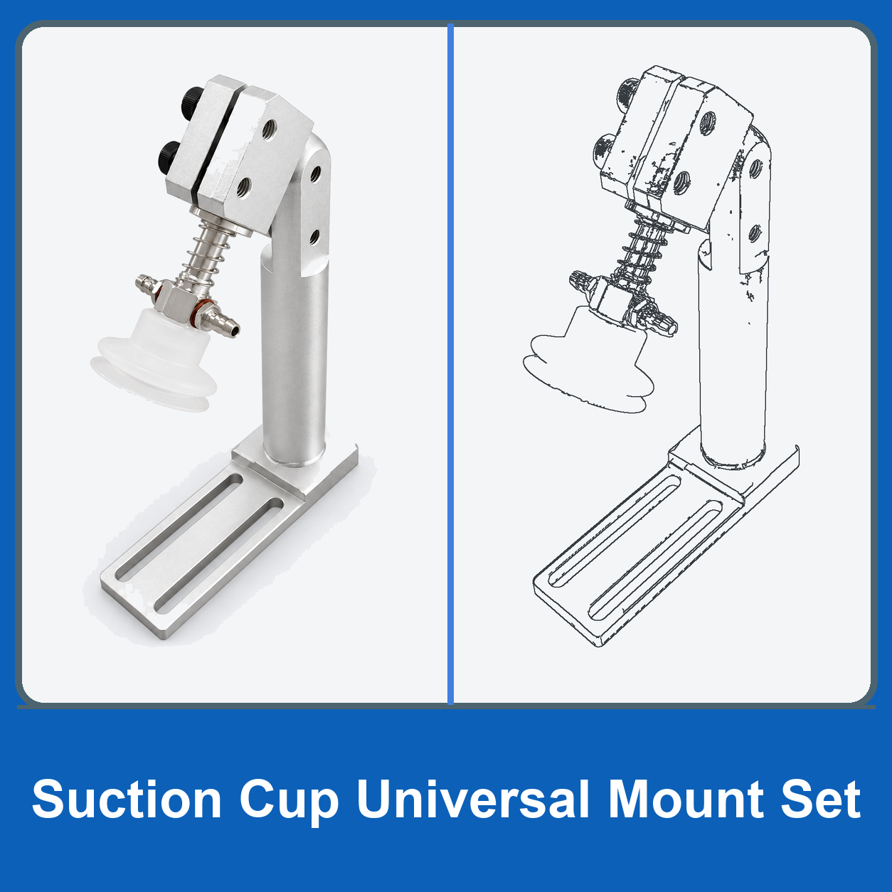
Confirm rod diameter, clamp opening, mounting thread, locating features and available fastener access. Use the selected dimensional drawing rather than assuming that a universal label means every fitting is compatible.
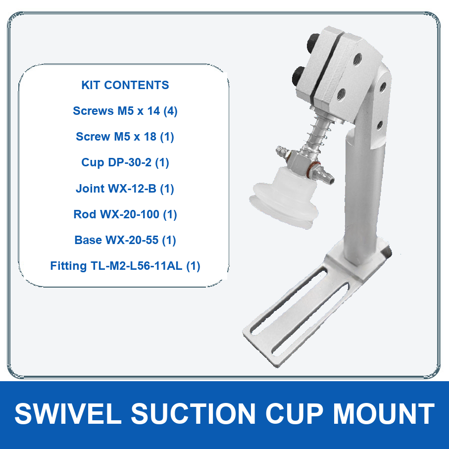
The linked fixture catalogue includes several different component types. A mounting rod, sliding bracket and rotary connector perform different tasks and should be specified separately.
3. Separate adjustment from locking
Identify how each joint is locked after alignment and obtain the relevant tightening requirements. Avoid relying on hand-tight adjustment for a production setup unless the component instructions explicitly permit it.
Record accepted positions with drawings or suitable reference marks. A technician should be able to restore the approved geometry without guessing from an unscaled photograph.
4. Check tubing and cable routes
Allow service access and controlled movement without pinching, excessive pull or rubbing. Verify routes across the complete motion envelope, including gripper opening and tooling changes.
Keep hoses away from clamping faces so tightening a bracket does not trap a line. Check that nearby joints cannot rotate into the workpiece or robot structure.
5. Commission the complete fixture
Follow the machine's approved procedure with the workpiece safely supported. Verify clearances, position repeatability and signs of movement at joints under the permitted cycle.
Fixture dimensions alone do not prove allowable load or stiffness. Request application-specific information if a component's rating is missing, especially for long cantilevers or repeated acceleration.
6. Prepare a layout-based quotation
Send the tool sketch, component list, interfaces, motion conditions and adjustment requirements. Identify whether the request concerns a single replacement bracket or a complete fixture layout.
Keep the accepted bill of materials and assembly settings with the maintenance file. Any later change to rod length, offset or gripper mass should trigger a review of the affected tool geometry and robot requirements.
7. Related products and next steps
Rods and fixture connectors · Swivel arms and mounting bases.
Send the complete model code, drawings or photographs, required quantity and application conditions to boltte@boltte.com. Confirm missing specifications in writing before ordering. Catalogue images illustrate the linked product family; they are not proof of compatibility, tested capacity or certification for your installation.