




ZR Two-Fluid Air/Water Spray Knives, 200 / 300 mm
ZR Two-Fluid Air and Water Spray Knives
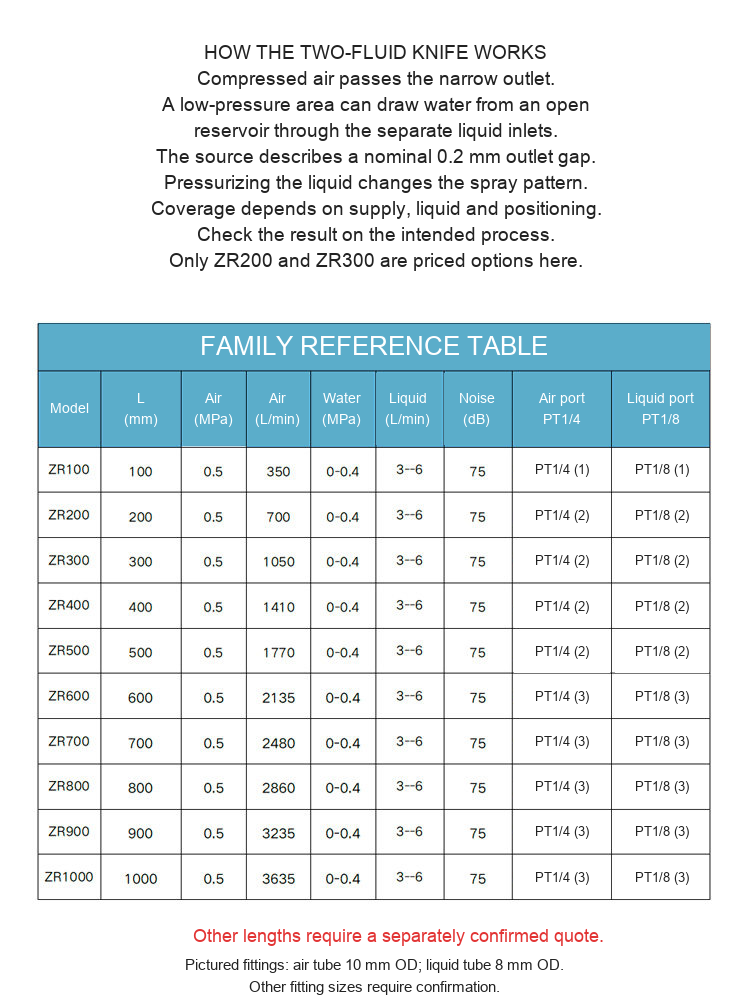
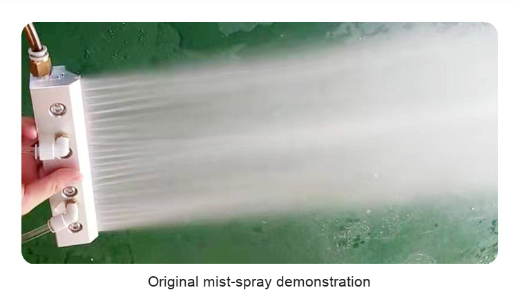
A ZR two-fluid spray knife has separate compressed-air and liquid connections. Air moving through its narrow outlet can draw liquid from an open reservoir to form a spray. A pressurized liquid supply can also be connected for a washing arrangement. Use it to distribute air and water along a working width for misting, pre-wetting, rinsing or surface cleaning. A suitable external air supply and liquid supply are required.
Available Models and Nominal Lengths
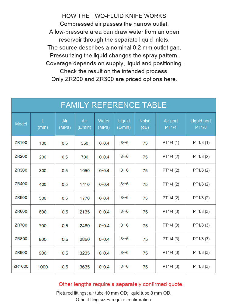
| Model | Nominal length | Air reference | Liquid reference |
|---|---|---|---|
| ZR200 | 200 mm (7.874 in) | 0.5 MPa; 700 L/min | 0-0.4 MPa; 3-6 L/min |
| ZR300 | 300 mm (11.811 in) | 0.5 MPa; 1050 L/min | 0-0.4 MPa; 3-6 L/min |
Each unit is one spray knife in the selected nominal length. The original photographs are shared family views; they are not exact-length scale drawings. The 100-1000 mm family table below is retained as reference material, but only the two priced 200 and 300 mm models are selectable here. Other lengths and materials need a separately confirmed quotation.
What It Can Do
| Use | How it is arranged | What to check |
|---|---|---|
| Misting / pre-wetting | Use the compressed-air flow with the separate liquid feed to distribute mist across an accessible surface. | Test liquid pickup, hose routing, working distance and the required coverage. |
| Water-assisted washing / rinsing | Connect a controlled pressurized liquid supply as well as compressed air. | Check pressure, flow, drainage and compatibility with the workpiece. |
| Air-only blow-off | The source describes air discharge when only the compressed-air connection is supplied. | Check whether the air sheet suits the required loose-debris or water-removal task. |
Ports, Tubing and Dimensions
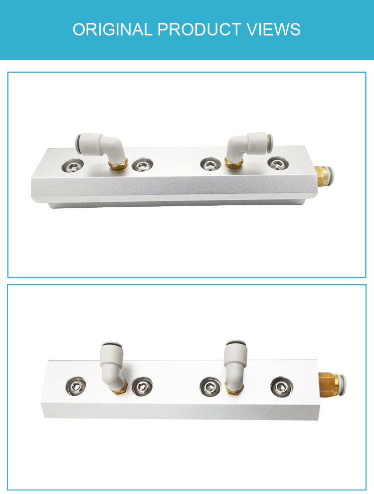
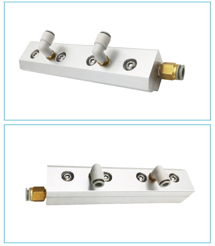
For ZR200 and ZR300, the supplied family table lists two PT1/4 air ports and two PT1/8 liquid ports. The drawing shows liquid connections on the top and air connection at an end; exact port locations and unused-end closure need confirmation for the supplied unit. The pictured fitting references are 10 mm outside-diameter air tube (0.394 in) and 8 mm outside-diameter liquid tube (0.315 in). PT designations are retained as supplied and should not be treated as NPT without checking fit.
The original family section shows a 44.5 x 37 mm profile (1.752 x 1.457 in). Other numerical dimensions and technical lines are retained in the drawing below. Confirm the length-specific mounting layout before drilling or machining. The source describes an aluminum-alloy body for the pictured family; no certified alloy grade is stated.
How the Liquid Is Introduced
With an open liquid feed, the air jet creates a low-pressure region that can draw water toward the outlet. The source describes a nominal 0.2 mm (0.008 in) outlet gap. With a pressurized liquid feed, the balance of liquid and air changes. Pickup height, line losses, liquid properties and the actual supply affect the result, so do not select only from the compressor tank pressure or a claimed spray distance.
Supply Reference and Included-Item Check
The supplied reference point is 0.5 MPa compressed air (5 bar, approximately 72.5 psi), with a liquid range of 0-0.4 MPa (0-4 bar, approximately 0-58 psi). Reference air use is 700 L/min for ZR200 and 1050 L/min for ZR300; the listed water use is 3-6 L/min. The source lists 75 dB but does not provide a measurement method or distance. These figures describe supplier reference conditions, not every installed process.
Liquid-inlet fittings are named as a standard accessory in the supplied attributes. Photos show typical connectors, not a complete installation kit. Confirm the fitting sizes, connector contents and required tubing before ordering. Compressor, regulator, liquid reservoir/pump and the machinery or workpieces shown are not specified as included.
Installation and Adjustment
- Choose 200 or 300 mm nominal length for the intended working width and available space.
- Confirm the required air delivery, liquid feed arrangement and matching threads/tube sizes.
- Mount the body on a suitable support without distorting the outlet. Keep the outlet and connections clean.
- Connect air and liquid to their separate ports. Use an appropriate controlled supply for the selected operating arrangement.
- Start with a controlled air/liquid setting and observe the pattern. Adjust the feeds, angle and distance on the actual workpiece.
- Check coverage and results at the intended process speed. Isolate and depressurize before changing connections or servicing.
Before Ordering
Send nominal length, available air pressure/flow, liquid type and supply arrangement, working width/distance, and an installation photo or drawing to boltte@boltte.com for a fit check. Confirm material compatibility for the actual liquid and workpiece.
Original Product, Drawing and Application Images
The original views below show the product, connection layout, family reference table and two real spray demonstrations. The dark-background spray sheet is an illustration. Millimeter dimensions are retained, with calculated inch references where useful.



Modell / konfiguration / SKU
| Modell / konfiguration | SKU |
|---|---|
| ZR200 - 200 mm (7.874 in) | 4850733153869 |
| ZR300 - 300 mm (11.811 in) | 4850733153870 |