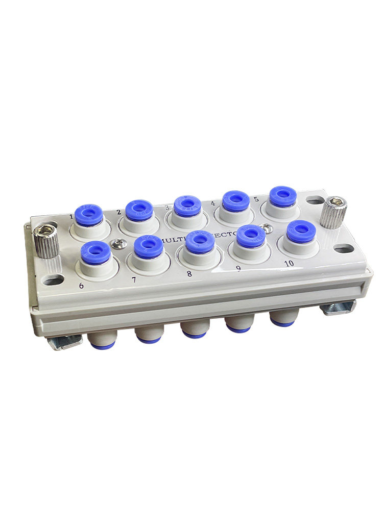
KDM10 KDM20 Multi-Tube Pneumatic Connectors, 4-8 mm
Vald Välj alternativ
KDM10 / KDM20 Multi-Tube Pneumatic Connectors
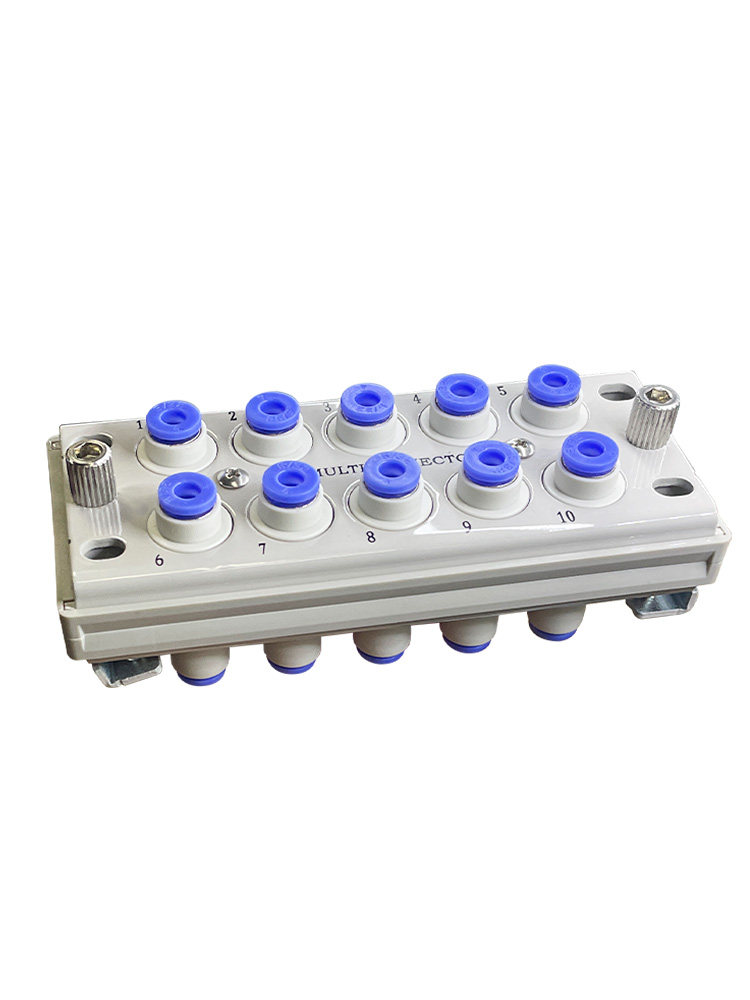
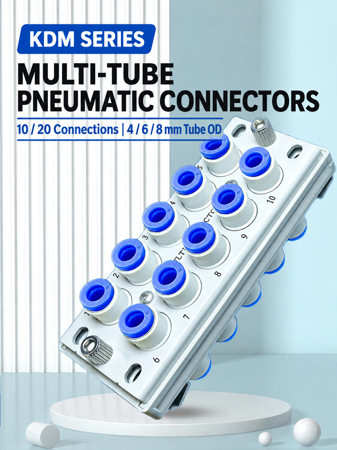
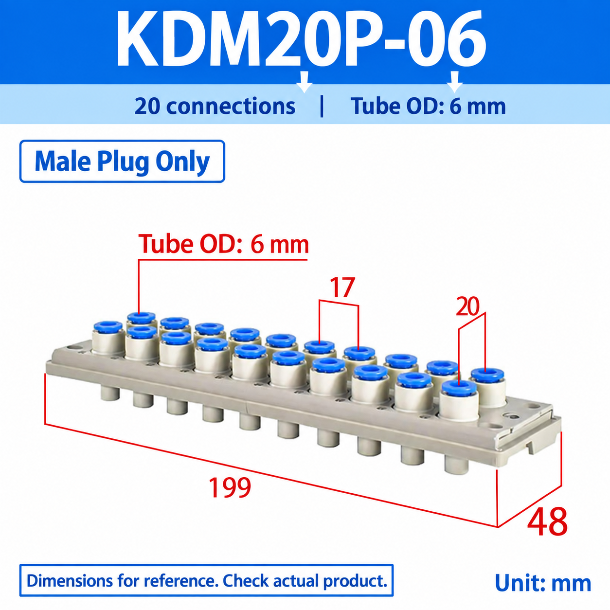
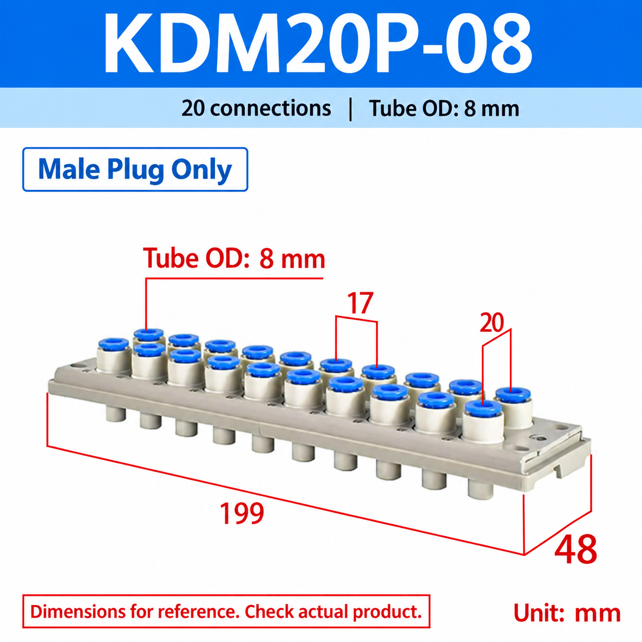
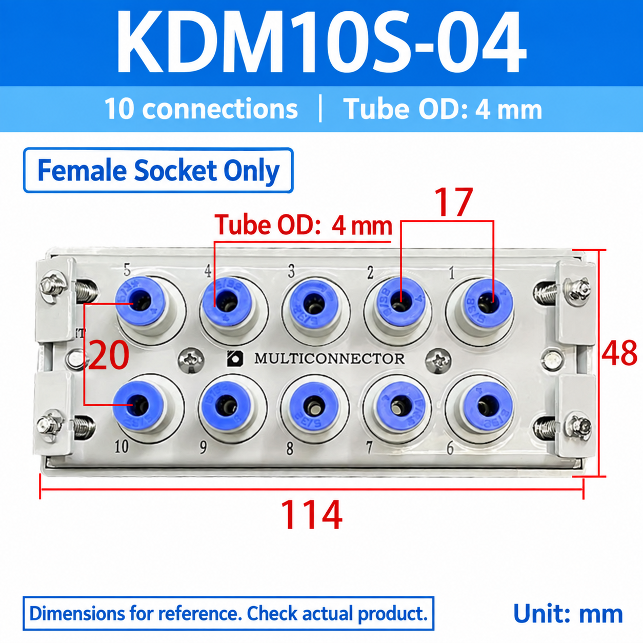
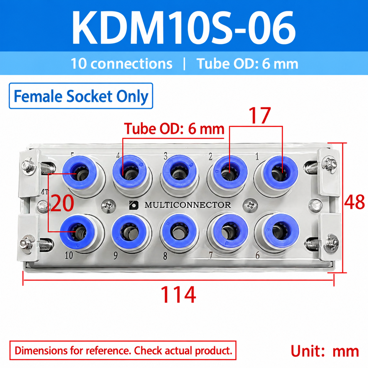
Rectangular multi-tube connectors with 10 or 20 connections for 4, 6 or 8 mm outside-diameter tubing. Choose a complete male-and-female set, a male plug only, or a female socket only. Single components are sold separately and are not complete sets.
Model selection and dimensions
Dimensions below are transcribed from the supplied model images in millimeters. Confirm the model, tube outside diameter and component type before ordering.
Model
Included component
Connections
Tube OD (mm)
Plate dimensions (mm)
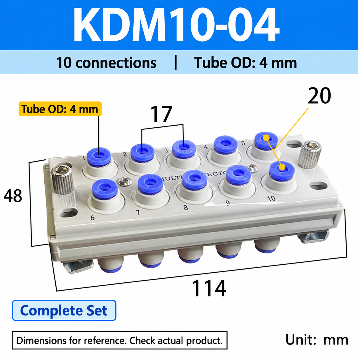
KDM10-04
Complete Set
10
4
114 x 48
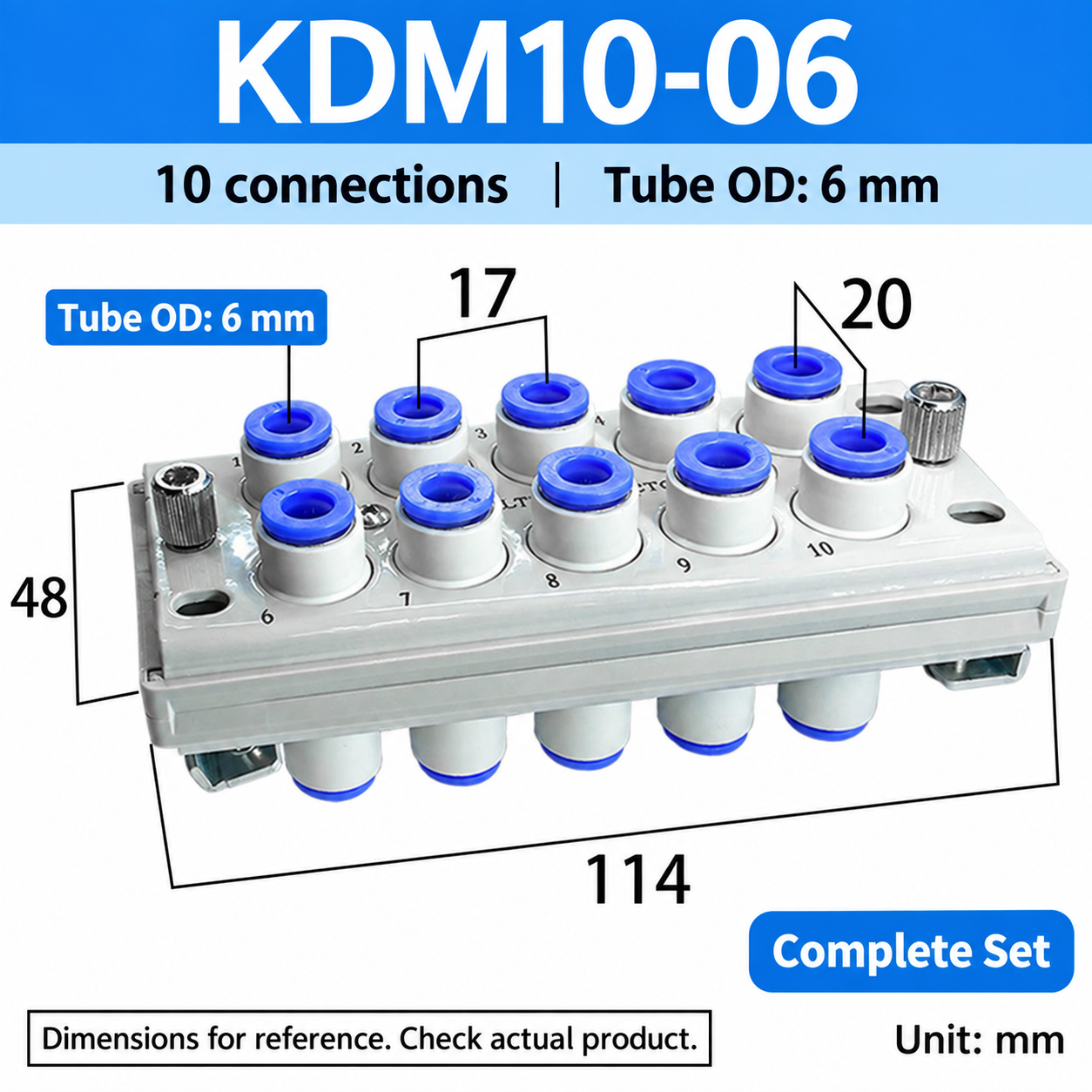
KDM10-06
Complete Set
10
6
114 x 48
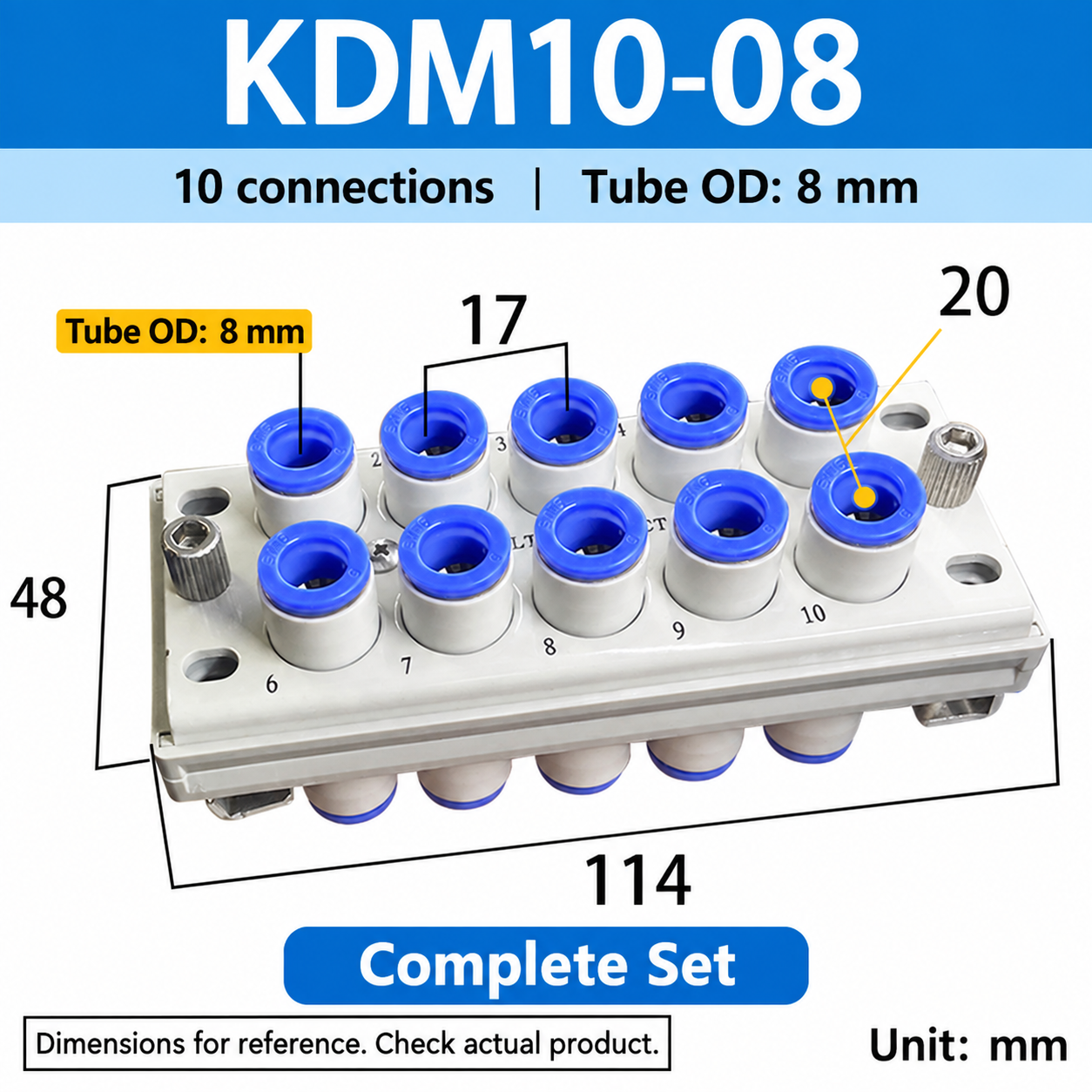
KDM10-08
Complete Set
10
8
114 x 48
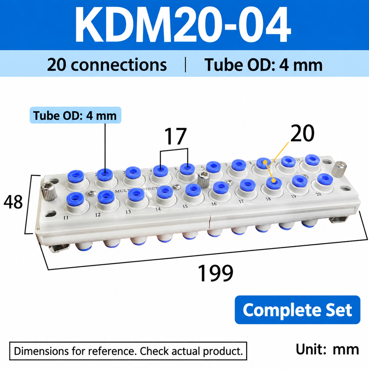
KDM20-04
Complete Set
20
4
199 x 48
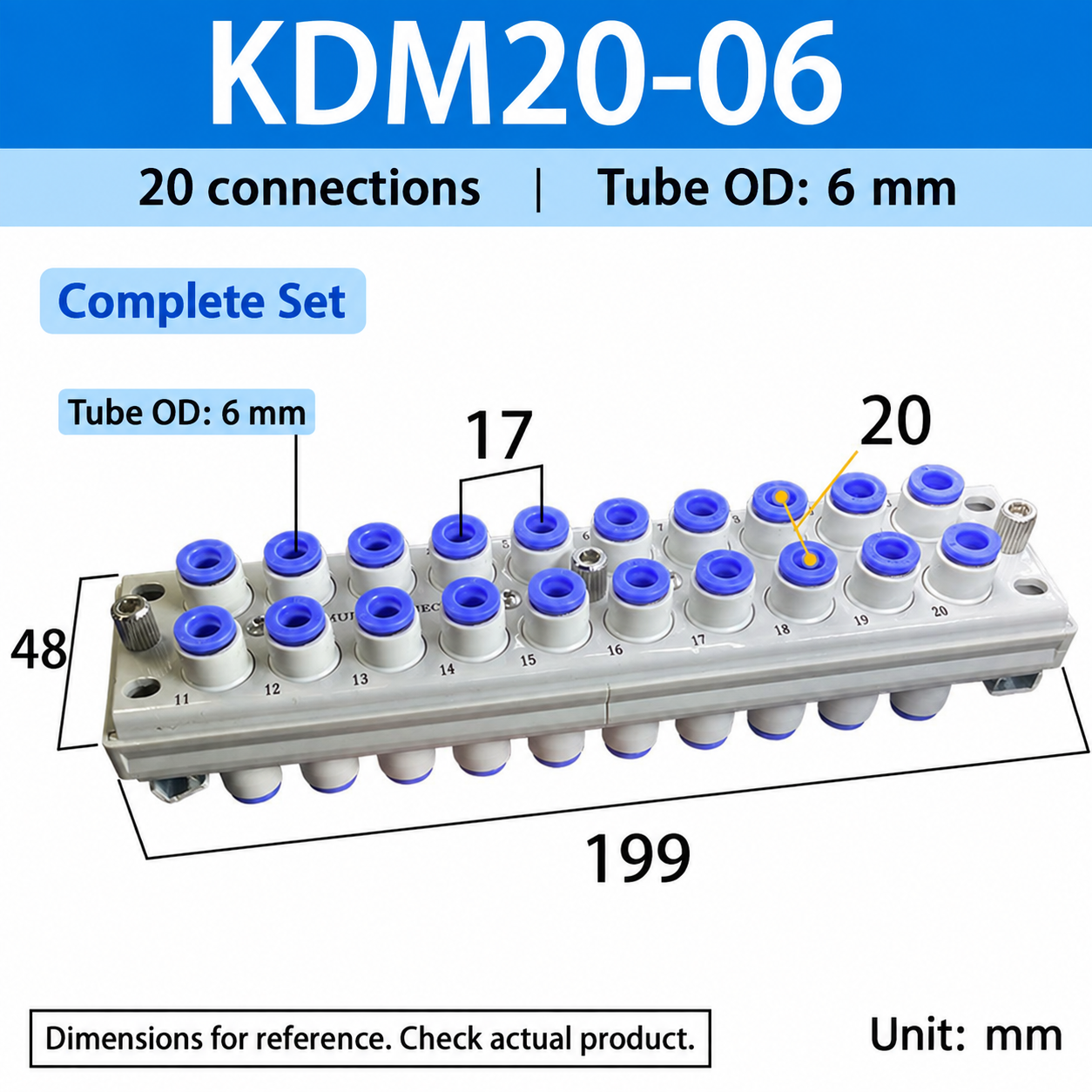
KDM20-06
Complete Set
20
6
199 x 48
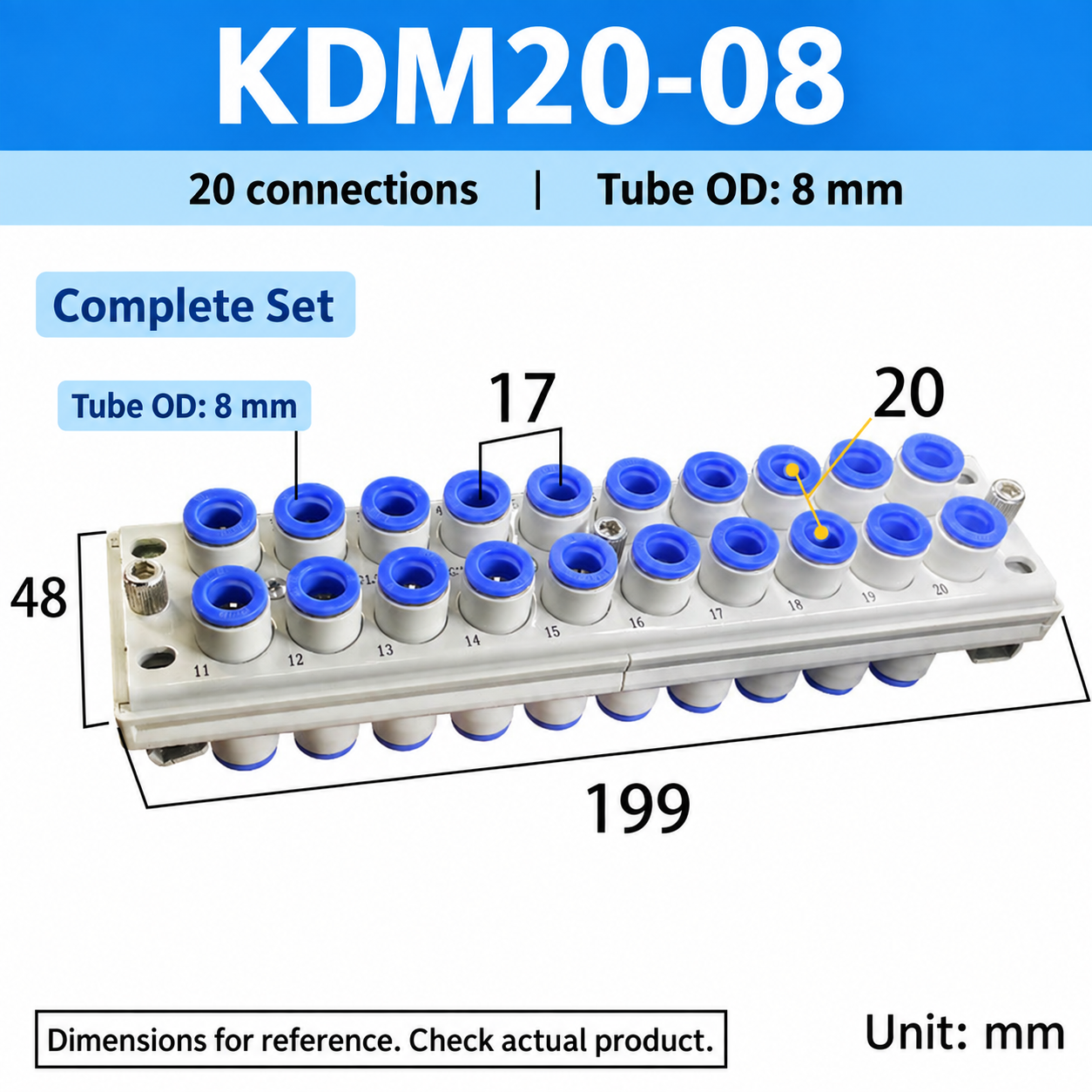
KDM20-08
Complete Set
20
8
199 x 48
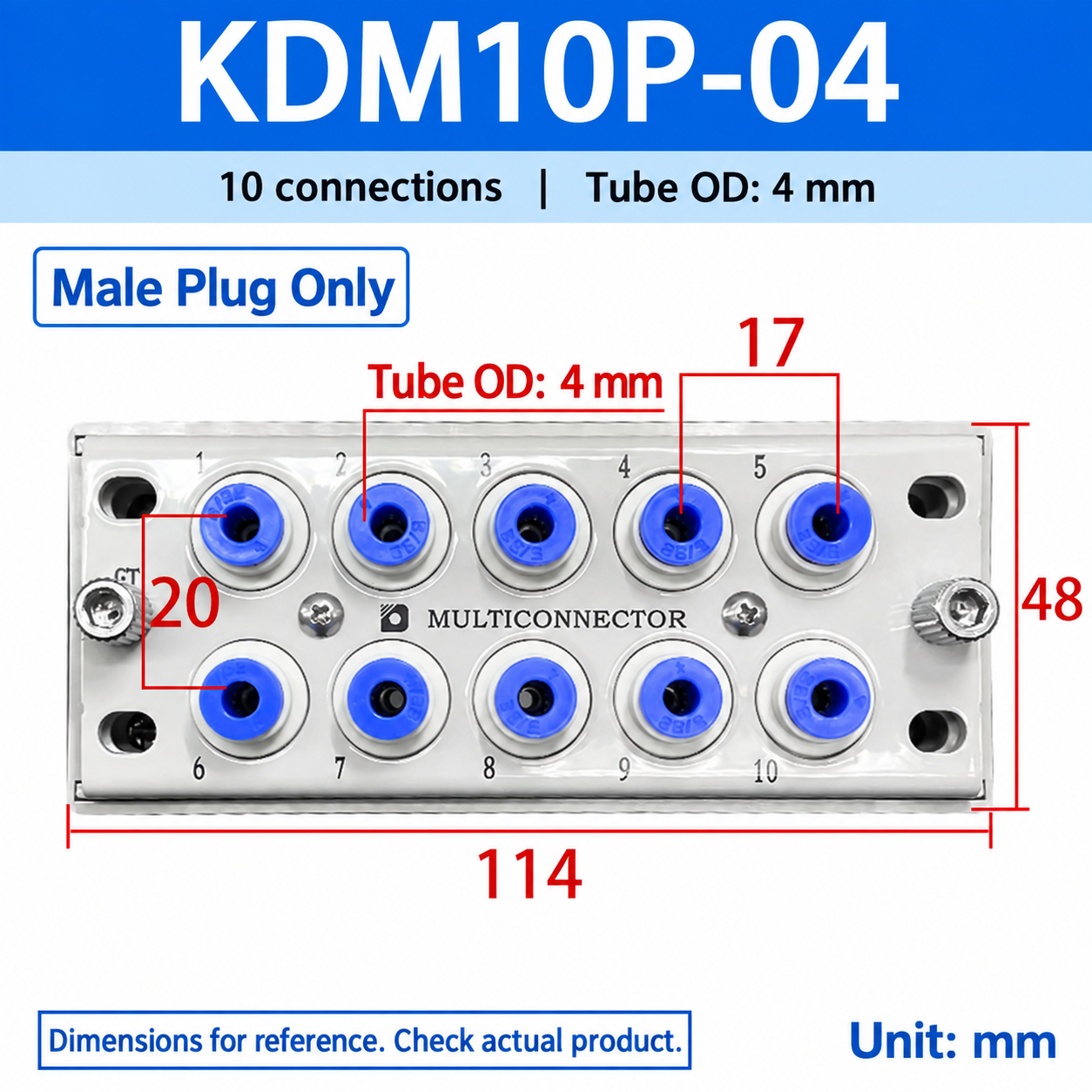
KDM10P-04
Male Plug Only
10
4
114 x 48
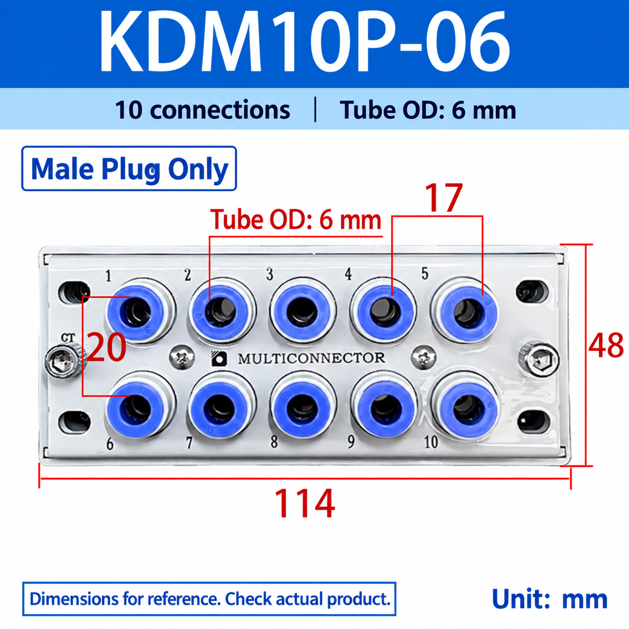
KDM10P-06
Male Plug Only
10
6
114 x 48
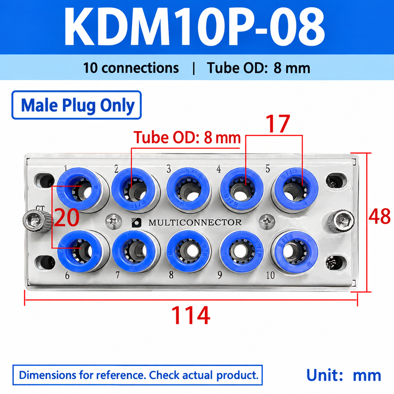
KDM10P-08
Male Plug Only
10
8
114 x 48
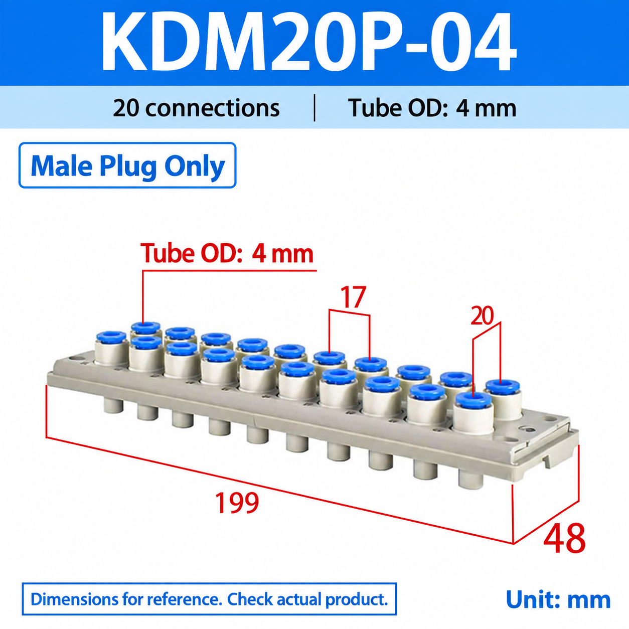
KDM20P-04
Male Plug Only
20
4
199 x 48
KDM20P-06
Male Plug Only
20
6
199 x 48
KDM20P-08
Male Plug Only
20
8
199 x 48
KDM10S-04
Female Socket Only
10
4
114 x 48
KDM10S-06
Female Socket Only
10
6
114 x 48
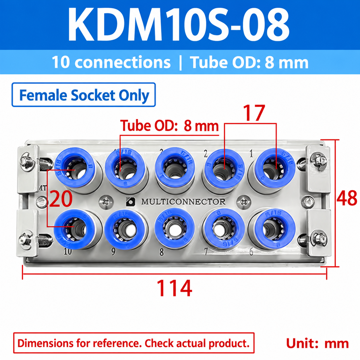
KDM10S-08
Female Socket Only
10
8
114 x 48
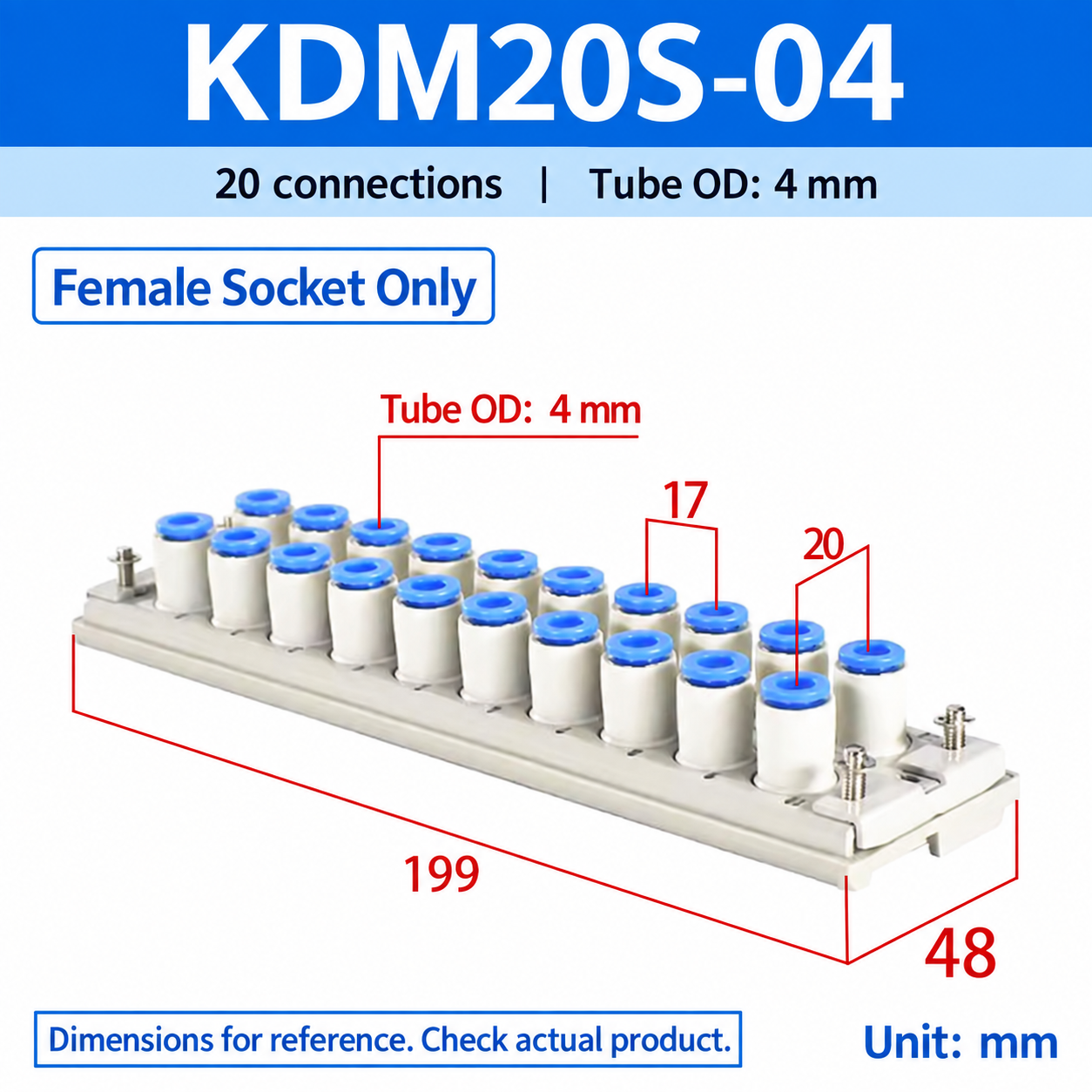
KDM20S-04
Female Socket Only
20
4
199 x 48
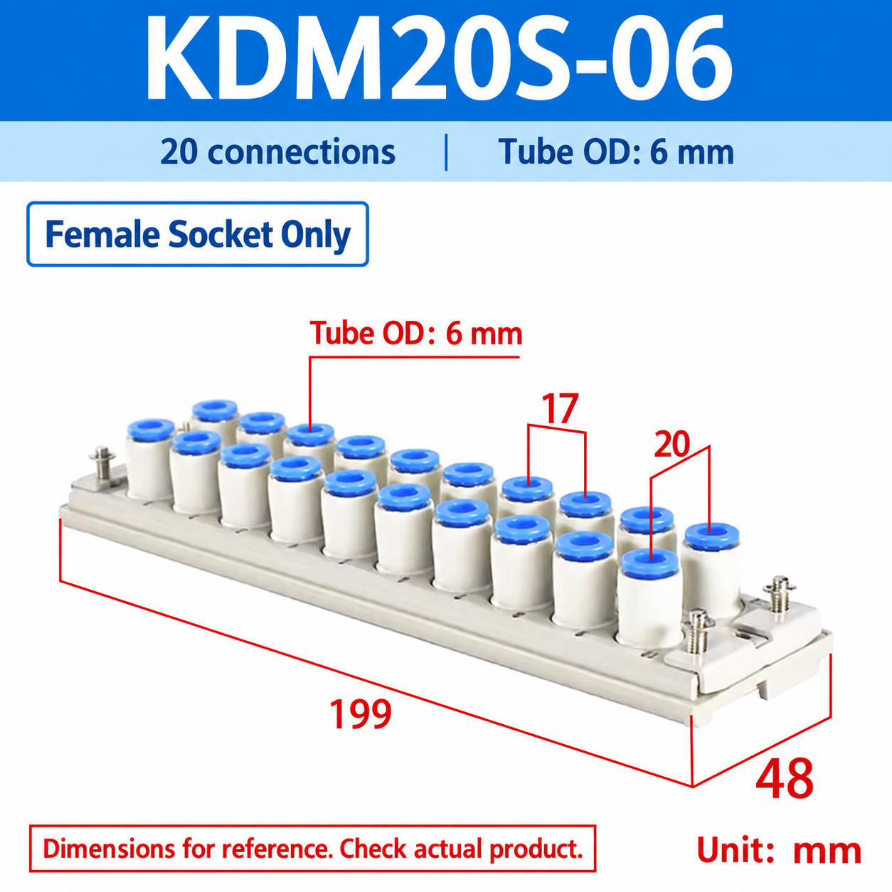
KDM20S-06
Female Socket Only
20
6
199 x 48
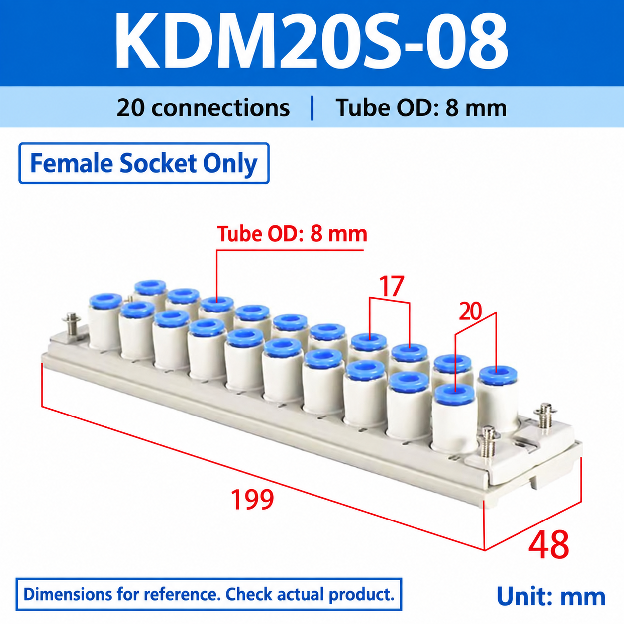
KDM20S-08
Female Socket Only
20
8
199 x 48
The images show 17 mm adjacent-port spacing and 20 mm row spacing. Dimensions are for reference; check the actual product and matching assembly. Only the selected model and component type are supplied.
KDM Series Multi-Tube Pneumatic Connectors
Connect and disconnect 10 or 20 pneumatic tubes together. The rectangular plug-and-socket assembly is designed for removable panels, machine sections and component replacement. Choose a complete set, a male plug only or a female socket only; the selected option determines what is supplied.
Compact connection, convenient maintenance
Multi-tube docking: connect or separate multiple lines together, reducing installation time and the risk of mixing up lines.
Space-saving layout: takes less mounting space than multiple separate panel-mount straight connectors.
Push-in tube connections: quick tube installation and removal.
Secure assembly: fastening screws hold the plug and socket halves together.
Resin construction: smooth, burr-free surfaces with hardness, pressure resistance and wear resistance described in the supplied product information.
Model coverage: 10- and 20-connection assemblies, with 4, 6 and 8 mm tube OD options offered on this page.
Sealed connections: sealing rings support pneumatic connection; observe the leakage limitation below.
Easy installation: standard panel-mount brackets allow installation from the panel front.
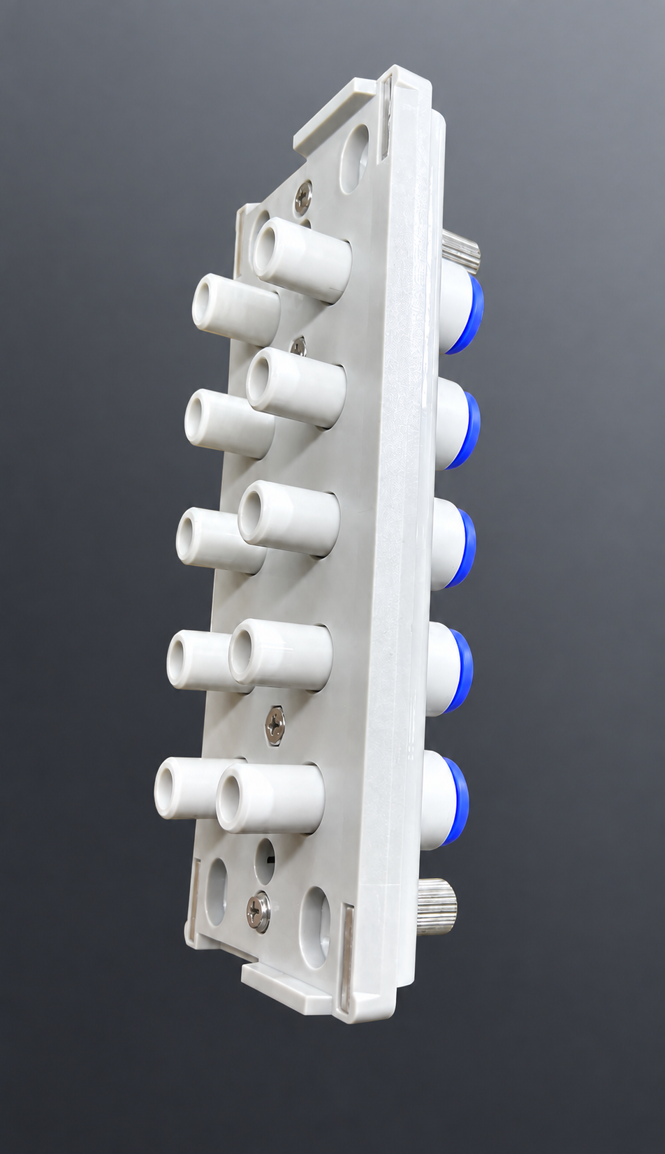
Resin body and blue push-in release collars
Male plug and female socket shown separately
Construction and component guide
The assembly uses standardized components and selected materials. The core parts are the push-in plug fittings, socket fittings, plug cover, socket cover, fastening screws, panel-mount brackets and bracket screws. The catalog also identifies the retaining plate, E-type retaining rings and sealing rings. Locating features align the mating halves at the correct position.
Component
Purpose
Push-in plug and socket fittings
Connect the pneumatic tubes; the socket fitting includes a sealing ring.
Plug cover and socket cover
Support the two mating halves.
Retaining plate and small cross-recessed screws
Retain individual fittings; remove the plate to change fitting positions or sizes.
Fastening screws
Join and secure the plug and socket assemblies.
Panel-mount brackets, bracket screws and E-type retaining rings
Secure the socket assembly in the panel opening.
Operating specifications
Parameter
Specification from supplied information
Series
KDM
Product
Rectangular multi-tube pneumatic connector
Fluid
Air
Positive operating pressure
0.1–1.0 MPa (product overview)
Catalog operating pressure range
−100 kPa to 1 MPa; subject to the leakage limitation below
Proof pressure
1.5 MPa
Ambient and fluid temperature
−5 to 60 °C; no freezing
Tube materials
FEP, PFA, nylon, soft nylon and polyurethane (PU); the product overview specifically lists nylon and PU
Tube outside diameters
4, 6 and 8 mm offered here; 3.2 mm appears in the supplied series reference only
Release collar color
Blue
Connections
10 or 20
Panel thickness
5 mm maximum in the drawing; verify fit and fastening clearance
Important: leakage is not zero. The catalog states that these connectors must not be used for vacuum holding or leakage tests. A sealed connection is not a zero-leak guarantee. The source overview gives a positive-pressure range, while the series catalog also describes vacuum service; confirm suitability for the actual application.
Actual product views
KDM20 — 20-connection assembly
KDM10 male plug — tube connection face
KDM10 female socket — mating-face detail
KDM10 female socket — tube connection faceKDM10 male plug — mating face
Model selection and reference weights
Select only the models shown in the purchase selector. The 3.2 mm / -23 entries below are retained as series-reference information, not additional purchasable variants. Weights are catalog reference values for the listed assemblies, not shipping weights.
Connections
Tube OD (mm)
Complete set
Reference mass (g)
10
3.2 — reference only
KDM10-23
300
10
4
KDM10-04
300
10
6
KDM10-06
300
10
8
KDM10-08
520
20
3.2 — reference only
KDM20-23
520
20
4
KDM20-04
520
20
6
KDM20-06
520
20
8
KDM20-08
950
Separate plug and socket assemblies
Connections
Tube OD (mm)
Male plug
Female socket
10
3.2 — reference only
KDM10P-23
KDM10S-23
10
4
KDM10P-04
KDM10S-04
10
6
KDM10P-06
KDM10S-06
10
8
KDM10P-08
KDM10S-08
20
3.2 — reference only
KDM20P-23
KDM20S-23
20
4
KDM20P-04
KDM20S-04
20
6
KDM20P-06
KDM20S-06
20
8
KDM20P-08
KDM20S-08
Single plug and socket assemblies are sold separately and are not complete sets. Release collars are blue.
Individual fitting references and mixed tube sizes
The catalog describes replaceable plug and socket fittings at individual positions, allowing a mixture of tube sizes within an assembly. This is technical reference information; individual replacement fittings and mixed-size assemblies are not added as purchase options on this page.
Tube OD (mm)
Plug fitting
Socket fitting with sealing ring
Release collar
3.2 — reference only
KDMP-23
KDMS-23
Blue
4
KDMP-04
KDMS-04
Blue
6
KDMP-06
KDMS-06
Blue
8
KDMP-08
KDMS-08
Blue
Use a cross-head screwdriver to loosen the small cross-recessed pan-head screws and remove the retaining plate from the cover.
Replace the fittings in the required positions, then refit the plate to the cover and tighten its screws.
KDM20 and KDM10 multi-tube connection examples; tubes shown for illustration
Main component materials
Part
Material listed in supplied catalog
Socket cover and plug cover
POM
Plate and bracket
SPCC; the supplied material table labels the finish as anodized — confirm the actual surface treatment for the ordered part
Fitting body
PBT; C3604 with electroless nickel plating for the 8 mm version
Chuck
SUS304
Guide
SUS304, electroless-nickel-plated C3604; PBT for the 8 mm version
Spring collet and release collar
POM
Sealing ring
NBR
Fastening screws, bracket screws and small cross-recessed pan-head screws
SWRM, nickel-plated
E-type retaining ring
SUS304
The supplied series reference describes a copper-ion-free specification with electroless nickel plating. Confirm the required material and finish for the selected configuration.
How to connect and disconnect
Disconnect: loosen the fastening screws to separate the plug side from the socket side.
Connect: align the mating locating features and fit the plug cover to the socket assembly. Tighten the fastening screws by hand, then secure them with a No. 4 (4 mm) hex key.
Panel mounting and removal
The standard brackets allow installation from the front of the panel without separate mounting-screw holes. Prepare the rectangular panel cutout shown below. The descriptive text specifies a panel thinner than 5 mm, while the drawing marks 5 mm maximum; check the actual panel and assembly.
Use a cross-head screwdriver (JIS No. 2) to loosen the four bracket screws on the socket side until the brackets contact the retaining rings above them.
Slide the brackets inward along the elongated holes, then insert the connector into the panel opening.
Move the bracket screws outward and tighten them with the screwdriver to secure the socket cover.
For removal, loosen the bracket screws until the brackets contact the retaining rings, slide the brackets inward and remove the connector from the panel.
Dimensions and panel cutouts
All dimensions are in millimeters. Drawings below are original source views displayed without redrawing the product geometry. Parenthesized heights apply to the -08 (8 mm tube OD) versions.
Dimension
KDM10
KDM20
Plate length × width
114 × 48
199 × 48
Adjacent-port pitch
17
17
Row spacing
20
20
Overall height
47.1 (53 for KDM10-08)
47.1 (53 for KDM20-08)
Lower height indicated in side view
24 (28 for KDM10-08)
24 (28 for KDM20-08)
Step indicated in side view
5
5
Panel cutout length
109 ± 0.2
194 ± 0.2
Panel cutout width
45 ± 0.2
45 ± 0.2
Panel thickness in drawing
5 maximum
5 maximum
Hex socket size and quantity
4 mm across flats × 2
4 mm across flats × 3
KDM10 — plan view, 114 × 48 mm
KDM10 — panel cutout, 109 ± 0.2 × 45 ± 0.2 mm
KDM20 — plan view, 199 × 48 mm
KDM20 — panel cutout, 194 ± 0.2 × 45 ± 0.2 mm
KDM10 — side profile and 17 mm port pitch
KDM20 — side profile and 17 mm port pitch
Confirm the exact model, mating component, tube outside diameter, panel cutout and operating conditions before installation. Accessories, tubes and other configurations shown in the reference illustrations are not included unless specified by the selected option.
Modell / konfiguration / SKU
KDM10 KDM20 Multi-Tube Pneumatic Connectors, 4-8 mm