


GTC Rubber-Insert Clamp Shaft Couplings, Aluminum Hubs, 15-39 mm OD
GTC Rubber-Insert Clamp Shaft Couplings
Flexible shaft couplings with two aluminum-alloy split-clamp hubs and a separate rubber insert. Select the outside diameter, overall length and offered machining range, then confirm the finished bore on each end. The bore range is not a self-adjusting hole. One selected option is one complete coupling, not a pair or an extra spare insert.
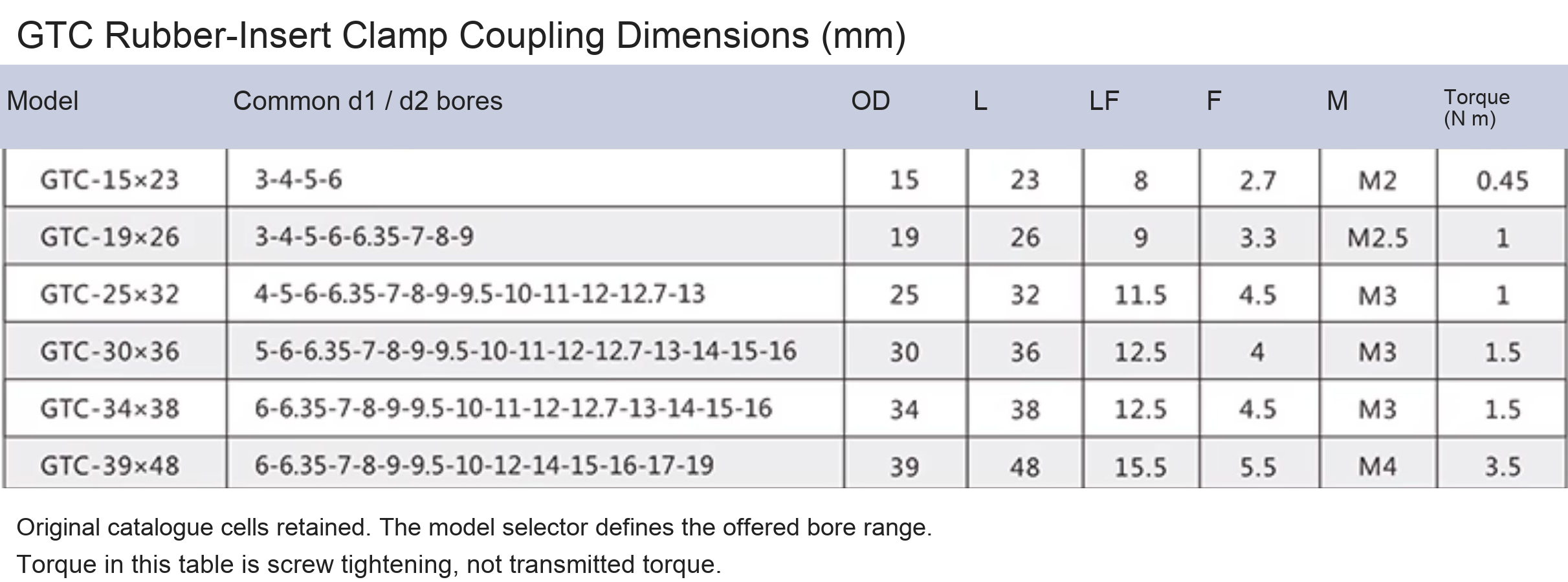
Model and Dimension Guide
Metric dimensions are authoritative. Inch equivalents are approximate, rounded to three decimal places. Metric screw threads remain metric.
| Selected configuration | OD | Length | Clamp screw | Tightening torque (N m) | Catalogue rated torque (N m) |
|---|---|---|---|---|---|
| GTC-34x38 / Bore 6-16 mm | 34 mm / 1.339 in | 38 mm / 1.496 in | M3 | 1.5 | 7 |
| GTC-15x23 / Bore 3-6 mm | 15 mm / 0.591 in | 23 mm / 0.906 in | M2 | 0.45 | 1 |
| GTC-19x26 / Bore 3-8 mm | 19 mm / 0.748 in | 26 mm / 1.024 in | M2.5 | 1 | 1.9 |
| GTC-25x32 / Bore 4-12 mm | 25 mm / 0.984 in | 32 mm / 1.260 in | M3 | 1 | 3.5 |
| GTC-30x36 / Bore 5-15 mm | 30 mm / 1.181 in | 36 mm / 1.417 in | M3 | 1.5 | 5.7 |
| GTC-39x48 / Bore 8-18 mm | 39 mm / 1.535 in | 48 mm / 1.890 in | M4 | 3.5 | 12 |
Construction and Flexible Element
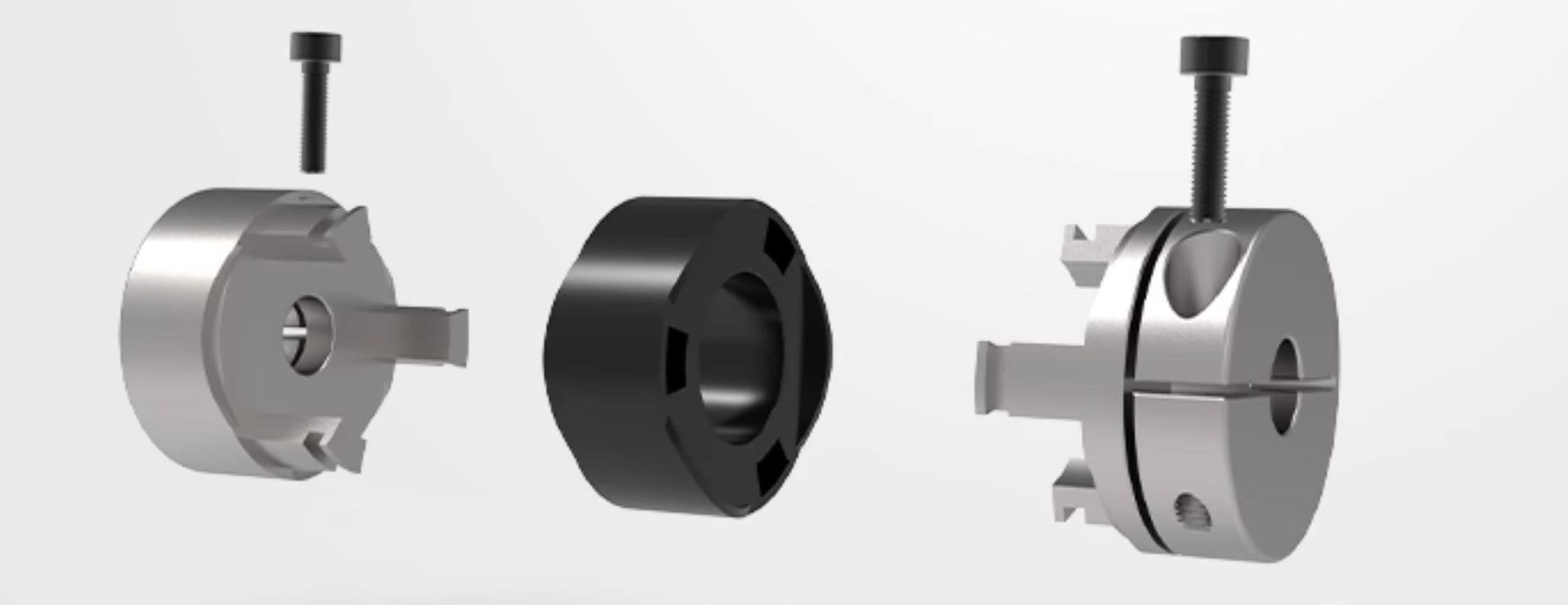
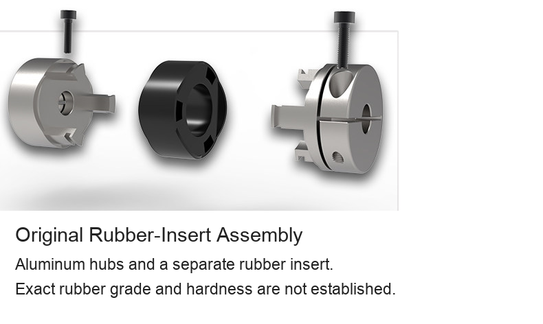
The supplied exploded view shows the hub fingers engaging the rubber element and clamp screws retaining the shafts. The source identifies aluminum alloy and rubber, but does not establish an exact alloy grade, rubber compound, hardness, certification or independently tested response. This is not the oval TPU-element GB design, a slotted one-piece beam coupling or an ordinary open-spider jaw coupling. No interchangeability is implied by a shared diameter and length.
Bores and Ordering
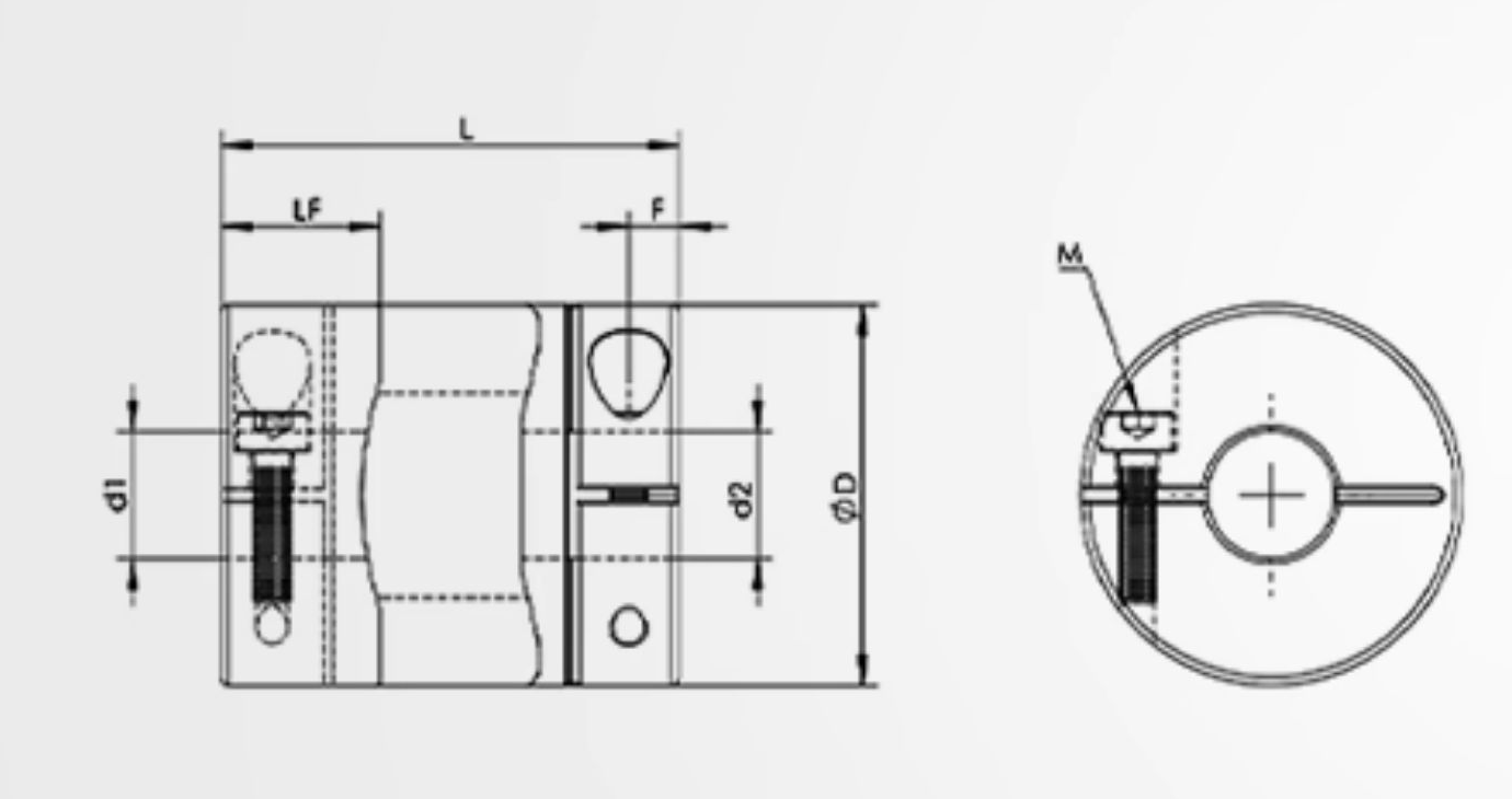
Specify both shaft diameters d1 and d2, fit requirements, engagement lengths and the final drawing before machining. The source uses H7 as a bore-fit reference; confirm the actual supplied tolerances and inspection requirements. Keyways or other special machining require separate dimensional confirmation and are not automatically included. The selected offer defines a narrower bore range for some models than the broad catalogue table; the selector is the offered range. No finished bore pair, key size or lead time is invented.
Original Photos and Drawings
The original white-background photograph is engraved GTC-34X38 and is the source photograph for the GTC-34x38 offer. The source model engraving is retained, not rewritten. Other selected models use the original family engineering drawing with their own dimensions in millimetres and inches. These are catalogue drawings, not individual finished-bore photographs or scale drawings. Original product geometry, arrows, engineering lines and numeric table cells are retained. Supplier logos, certification badges, promotional claims and manufacturing-machine advertising are omitted.
Technical Reference
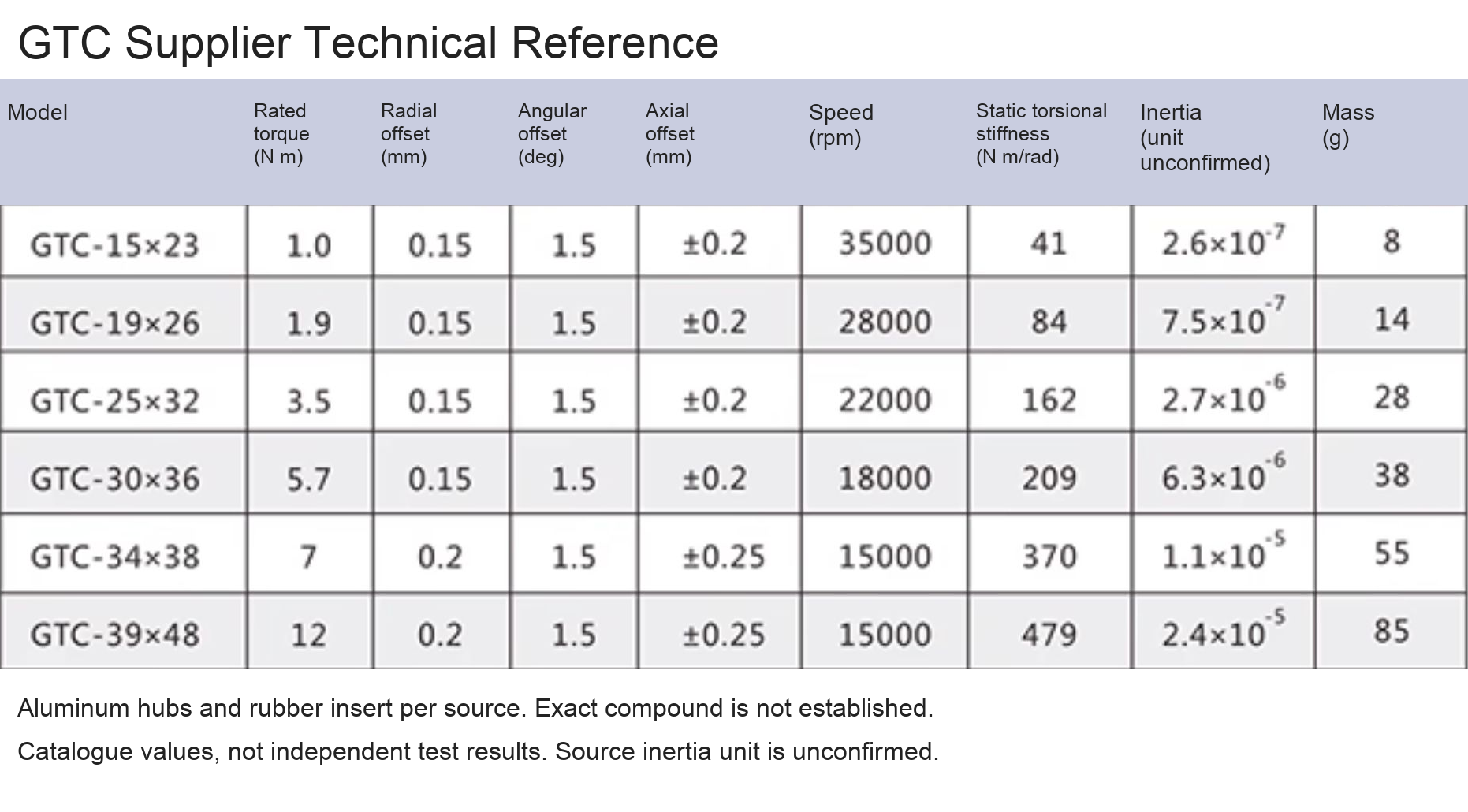
The source table gives nominal transmitted torque, allowable parallel/angular/axial offsets, maximum speed, static torsional stiffness and mass. Screw-tightening torque is not transmitted torque. Verify applicability to the finished bores, shaft clamping, alignment and actual duty. The source inertia unit is inconsistent and is marked unconfirmed. These are catalogue values, not independent test results. The original fastener panel states grade 12.9; confirm the actual supplied fasteners without inferring a material certificate.
Installation and Use
Check shaft spacing, the two bores, alignment, hub clearance and screw access before installation. Do not force misaligned shafts together or transmit assembly loads through the rubber insert. Isolate the drive before installation or maintenance, secure the assembly and use suitable guarding. Confirm the supplier-approved fastening and operating procedure. No lifetime, zero-backlash, chemical-resistance or accuracy guarantee is represented.



Modell / konfiguration / SKU
| Modell / konfiguration | SKU |
|---|---|
| GTC-34x38 / Bore 6-16 mm | 4788117043483 |
| GTC-15x23 / Bore 3-6 mm | 4788117043479 |
| GTC-19x26 / Bore 3-8 mm | 4788117043480 |
| GTC-25x32 / Bore 4-12 mm | 4788117043481 |
| GTC-30x36 / Bore 5-15 mm | 4788117043482 |
| GTC-39x48 / Bore 8-18 mm | 4788117043484 |