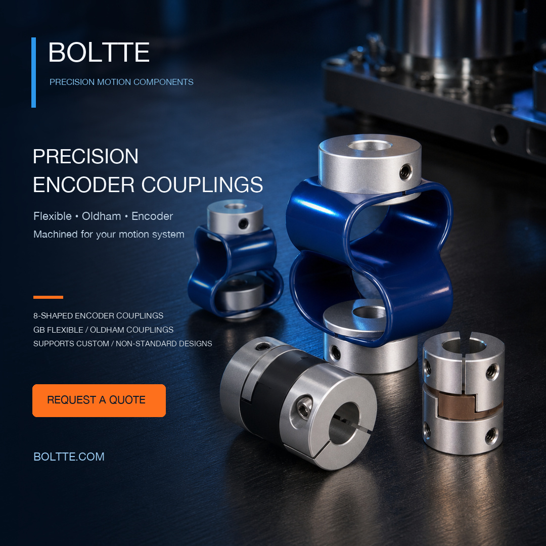

Custom & Non-Standard Shaft Couplings
Custom & Non-Standard Shaft Couplings
Non-standard customization is supported for all coupling types. BOLTTE accepts enquiries based on your drawings, samples or application requirements. Customize the coupling structure, shaft connections, dimensions, materials and other technical requirements for your equipment.
The examples pictured are only part of the range. If your coupling is not shown or listed below, send the design or sample details for review. Final feasibility, specifications, price and lead time are confirmed individually before production.
Coupling types available for customization
- 8-shaped and encoder couplings: custom hub bores, shaft-fixing details, overall dimensions and flexible-element requirements.
- Oldham / cross-slider couplings: hub and slider geometry, equal or unequal bores, clamp or set-screw connections, and POM or bronze slider requirements.
- Jaw / spider couplings: hub dimensions, jaw geometry, elastomer specification and shaft interfaces.
- Disc / diaphragm couplings: disc-pack arrangement, hubs, spacers and mounting patterns.
- Metal bellows couplings: bore sizes, hub connections, installation length and bellows requirements.
- Beam / slit couplings: beam or slot geometry, body dimensions, bore fit and clamping features.
- Rigid / split-clamp couplings: sleeve or split-hub structures, stepped bores, keyways and fastening details.
- Gear couplings: toothed hubs and sleeves, tooth geometry, shaft interfaces, lubrication and sealing requirements.
- Grid / spring couplings: hub grooves, spring-grid specification, covers and connection dimensions.
- Roller-chain couplings: sprocket and chain specification, shaft bores, keyways and cover details.
- Universal-joint couplings: end connections, joint arrangement, operating angle, fixed or telescopic length.
- Pin-and-bush couplings: flange geometry, pin arrangement, resilient-bush specification and bore configuration.
- Tyre / elastomeric couplings: hub interfaces, flexible elements and installation dimensions.
- Flange, spacer and other special couplings: bolt circles, intermediate lengths and other drawing-specified assemblies.
These types are open for custom enquiries; the detailed design and manufacturing requirements are subject to technical confirmation. Different coupling families are not interchangeable without checking the application.
What can be customized?
- Connections: equal or unequal shaft bores, stepped or tapered bores, keyways, splines, D-flats and threaded connections.
- Dimensions: outside diameter, overall length, hub length, shaft engagement, spacer length, bolt circles and mounting holes.
- Fixing: set screws, clamp hubs, split clamps, keys, flanges or another specified interface.
- Materials: specified aluminum alloy, stainless steel, steel, bronze or polymer grades for the applicable parts.
- Other requirements: heat treatment, surface finish, marking, inspection documents and agreed functional tests.
Technical information required for quotation
Please provide the following target requirements. If something is unknown, tell us about the equipment and operating conditions so it can be reviewed. These are enquiry fields, not universal product ratings.
- Application and coupling type: equipment, driven load, new design or replacement, reference model, drawing number and revision.
- Both shaft connections: input shaft / bore d1 and output shaft / bore d2, in mm or inches; shaft tolerance, bore fit, engagement length, keyway or spline details, and fixing method.
- Installation space: maximum outside diameter D, total length L, distance between shaft ends, hub lengths, clearance and mounting-hole dimensions.
- Torque and loading: continuous working torque and any specified rated-torque requirement (N·m); peak torque and duration; starting, braking, shock loads, reversals and duty cycle. If torque is unknown, provide motor power and speed at the coupling.
- Speed: normal and maximum rpm, direction of rotation, acceleration/deceleration and any balancing requirement.
- Misalignment: parallel / radial offset (mm), angular misalignment (degrees) and axial movement (mm), stated separately. Identify which occur simultaneously and whether they change during operation.
- Dynamic and positioning requirements: acceptable backlash, torsional stiffness, inertia, positioning accuracy, vibration or noise limits, with units and acceptance conditions.
- Materials and environment: material grades, hardness / heat treatment, finish, operating temperature, oil or chemical exposure, moisture, corrosion and any insulation requirement.
- Inspection and acceptance: critical dimensions and datums, runout or other geometric tolerances, material documents and agreed dimensional or functional tests.
- Quantity and delivery: prototype quantity, order quantity, expected repeat volume, requested delivery date and destination.
Attach a dimensioned PDF drawing and STEP, DWG or DXF files when available. Identify the controlling revision and critical features; a 3D model alone may not define all tolerances. For a replacement item, clear photos and measured dimensions can support the initial review.
Selection note: Torque, speed and allowable movement depend on the chosen design and operating conditions. Separate maximum misalignment values must not be assumed to apply simultaneously. Rigid couplings require suitable shaft alignment. Final tolerances and performance must follow the approved specification.
Custom order process
- Send drawings, sample details or application requirements.
- Review feasibility, dimensions, materials, inspection scope, quotation and lead time.
- Confirm the drawing revision and order requirements before production; arrange a prototype or first article where agreed.
- Produce and inspect to the confirmed requirements, then supply the agreed records, packaging and shipment.
Quotation required: Final price, minimum order quantity, lead time and any sample or tooling charges depend on the approved design and order quantity. Please obtain a written quotation before ordering a non-standard configuration.
Product examples
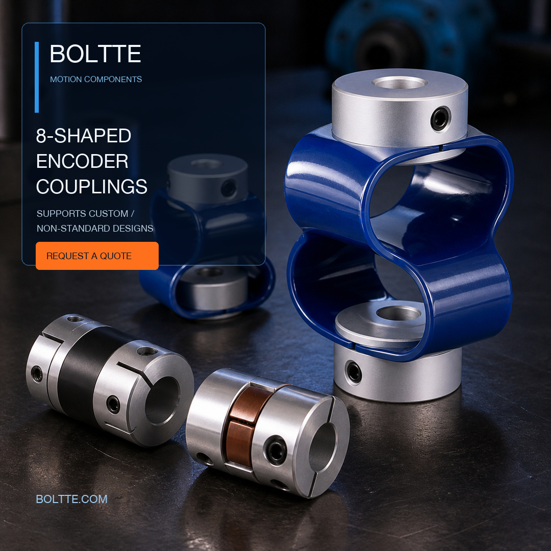
Illustrative render for reference only. The image shows selected coupling types, not the full customization range or a dimensional drawing. Delivered products follow the approved drawing and written quotation.
Request your custom coupling quote
Upload your drawings and project requirements. If you do not have a drawing yet, contact us with your application or sample details.