PCV Pilot-Operated Pneumatic Check Valves and Tube Fitting Configurations
PCV Pilot-Operated Pneumatic Check Valves
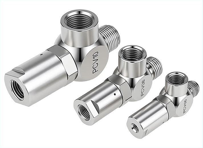
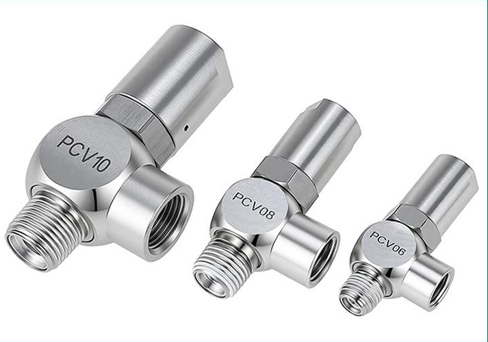
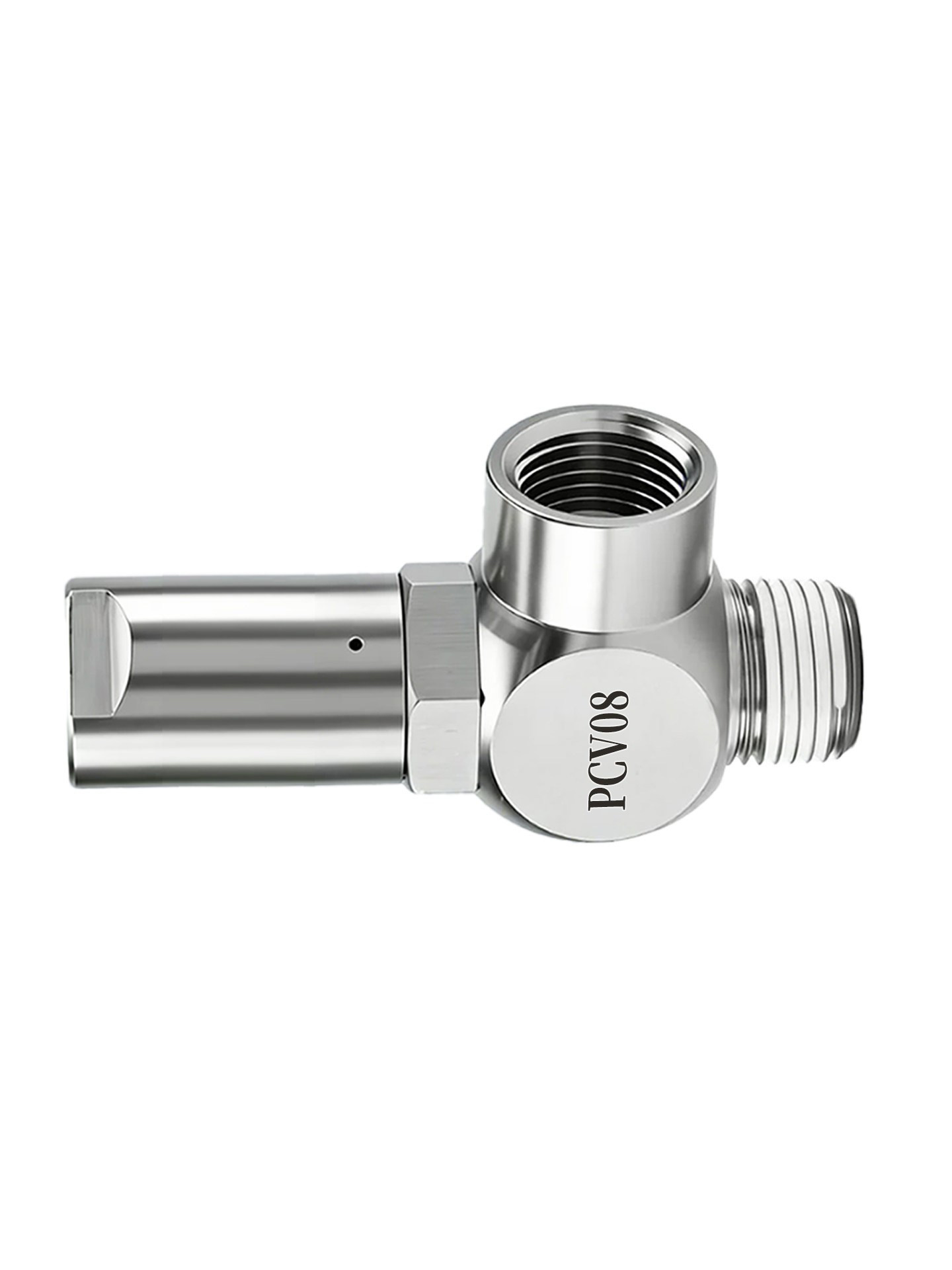
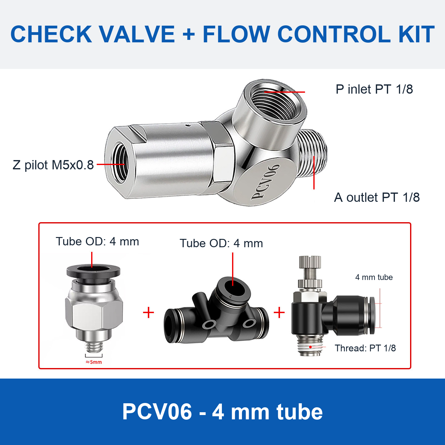
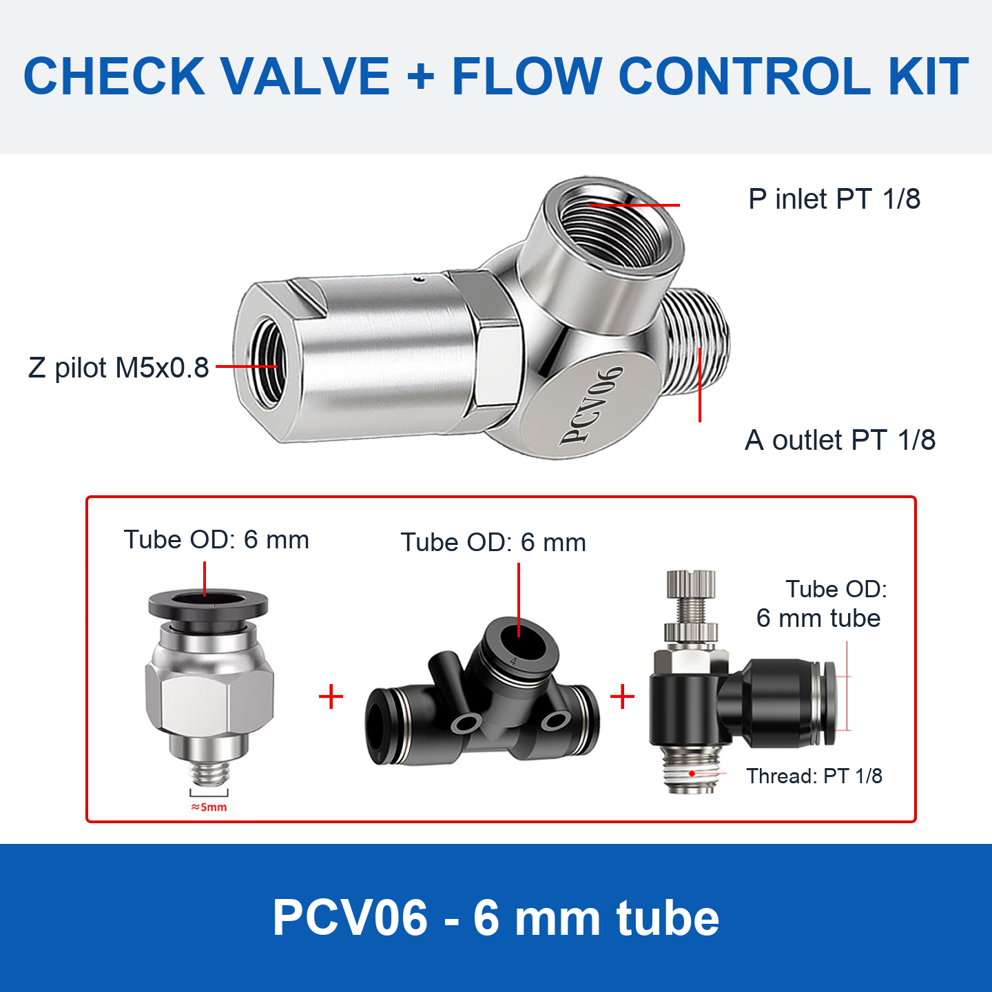
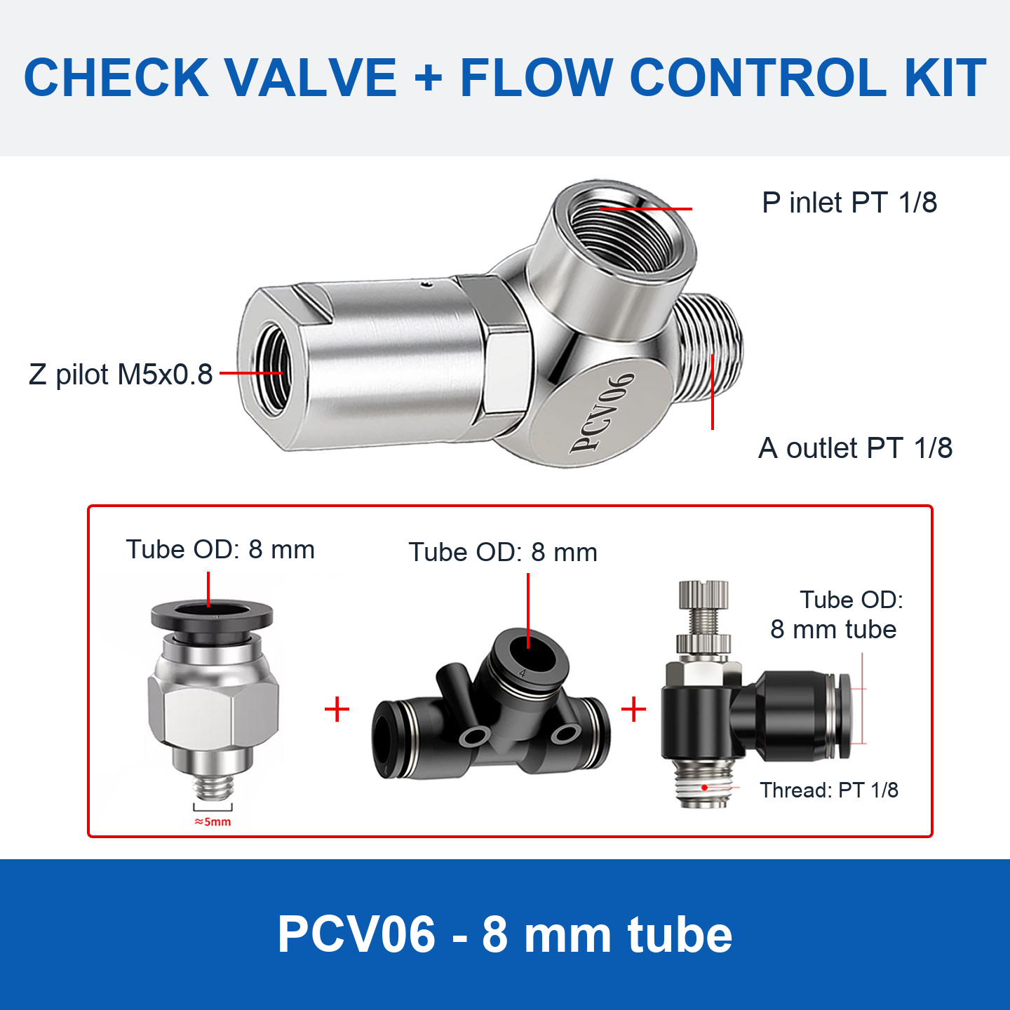
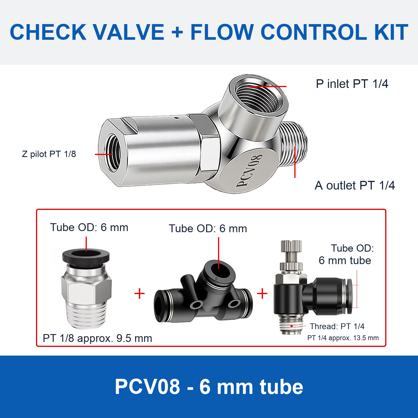
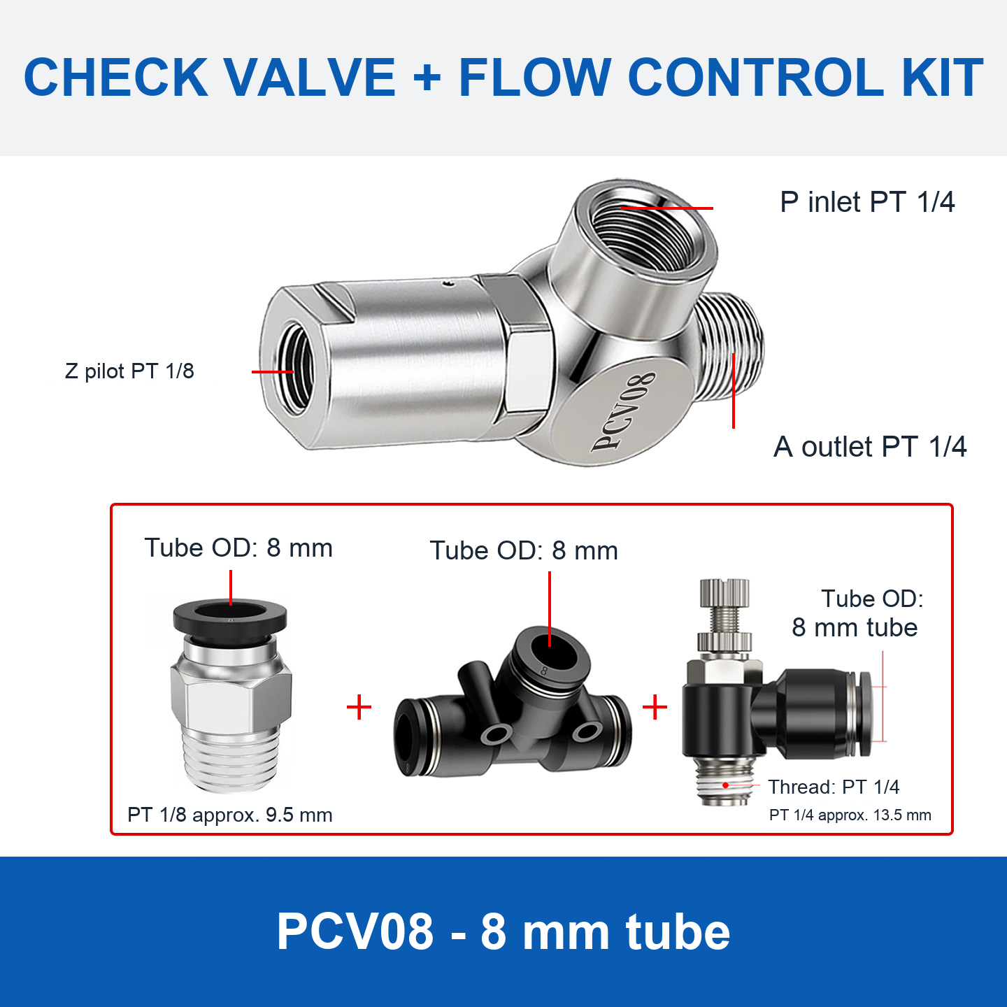
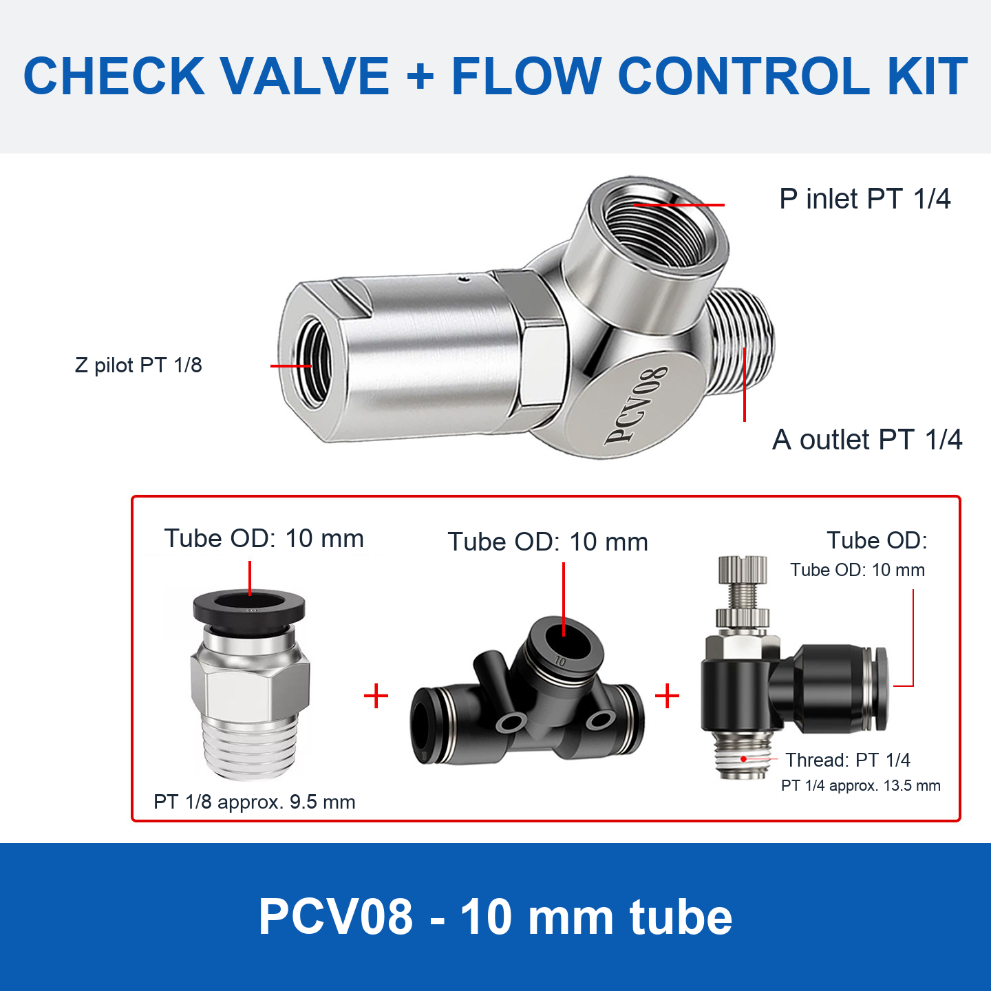
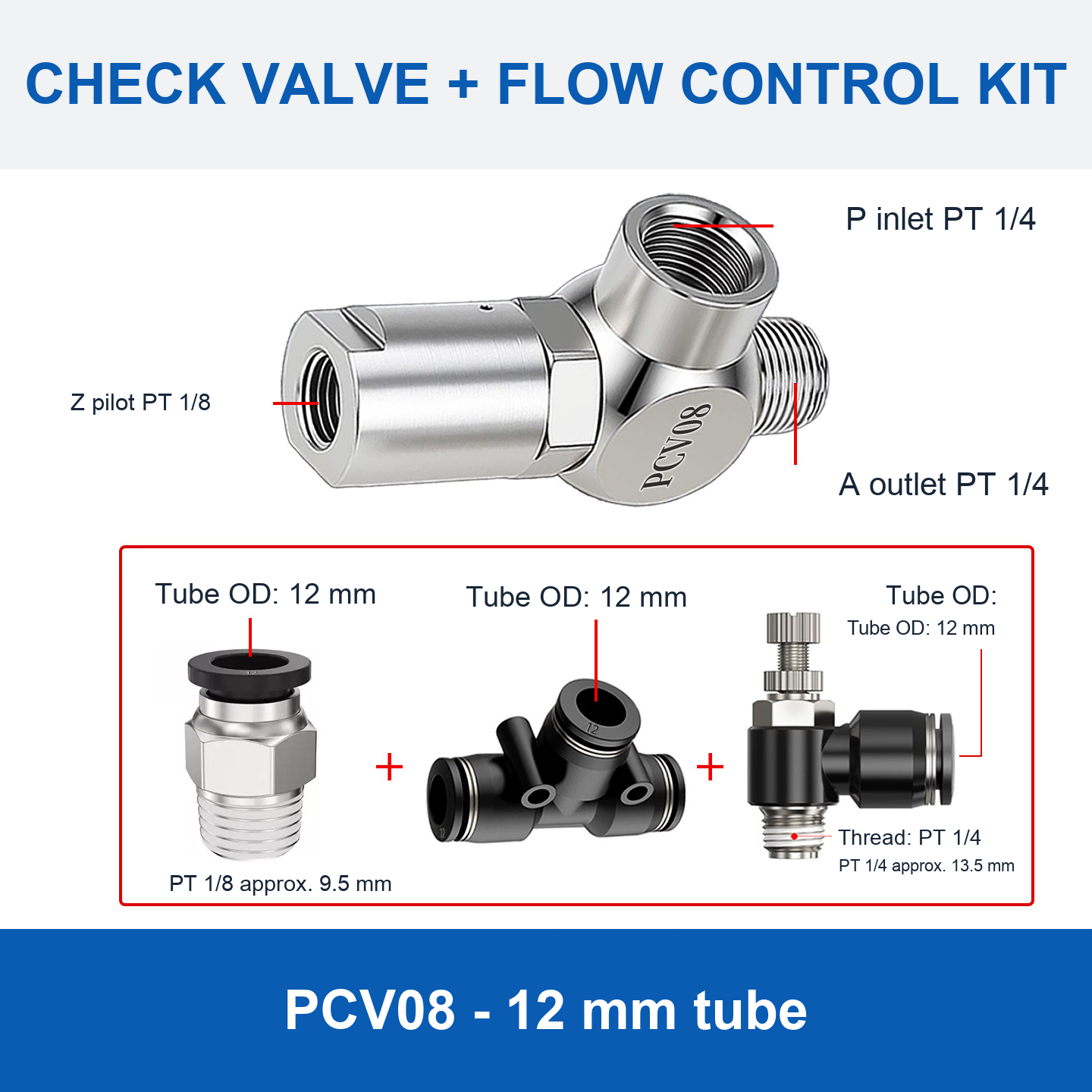
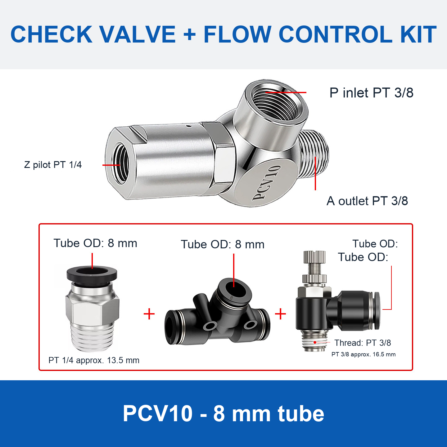
PCV06, PCV08, PCV10 and PCV15 pilot-operated check valves for pneumatic circuits. Choose a valve-only option, a flow-control accessory kit, or a push-in fitting kit. Each model selection has its own image or model reference card.
Choose the Configuration
- PCV06 / PCV08 / PCV10 / PCV15: base valve options.
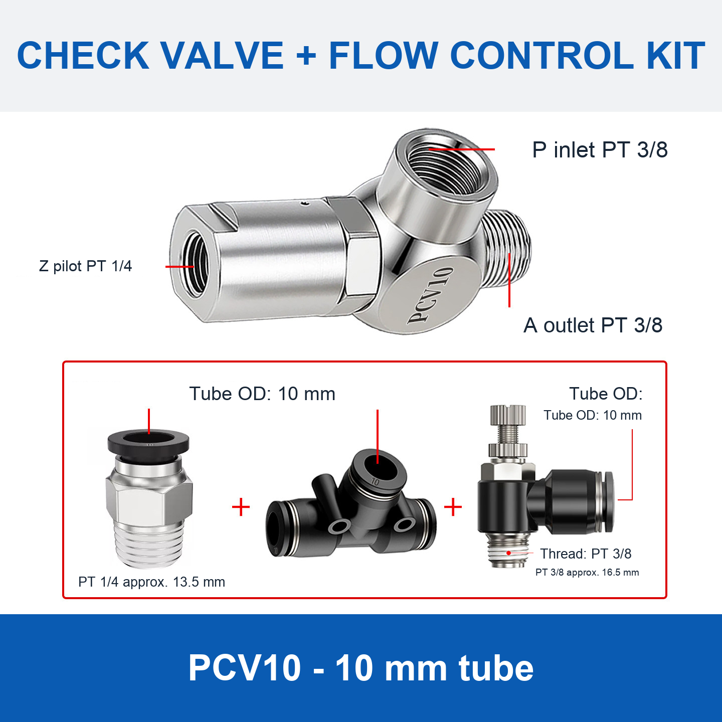
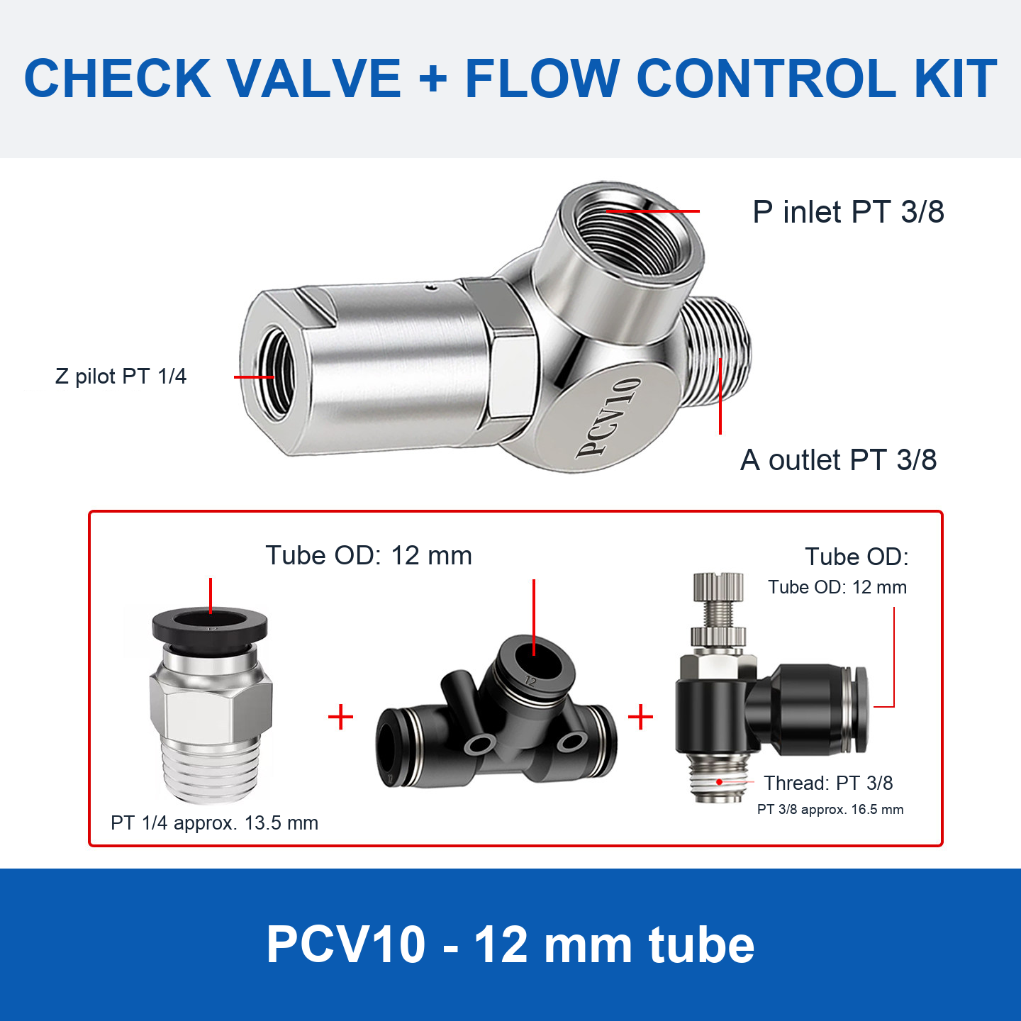
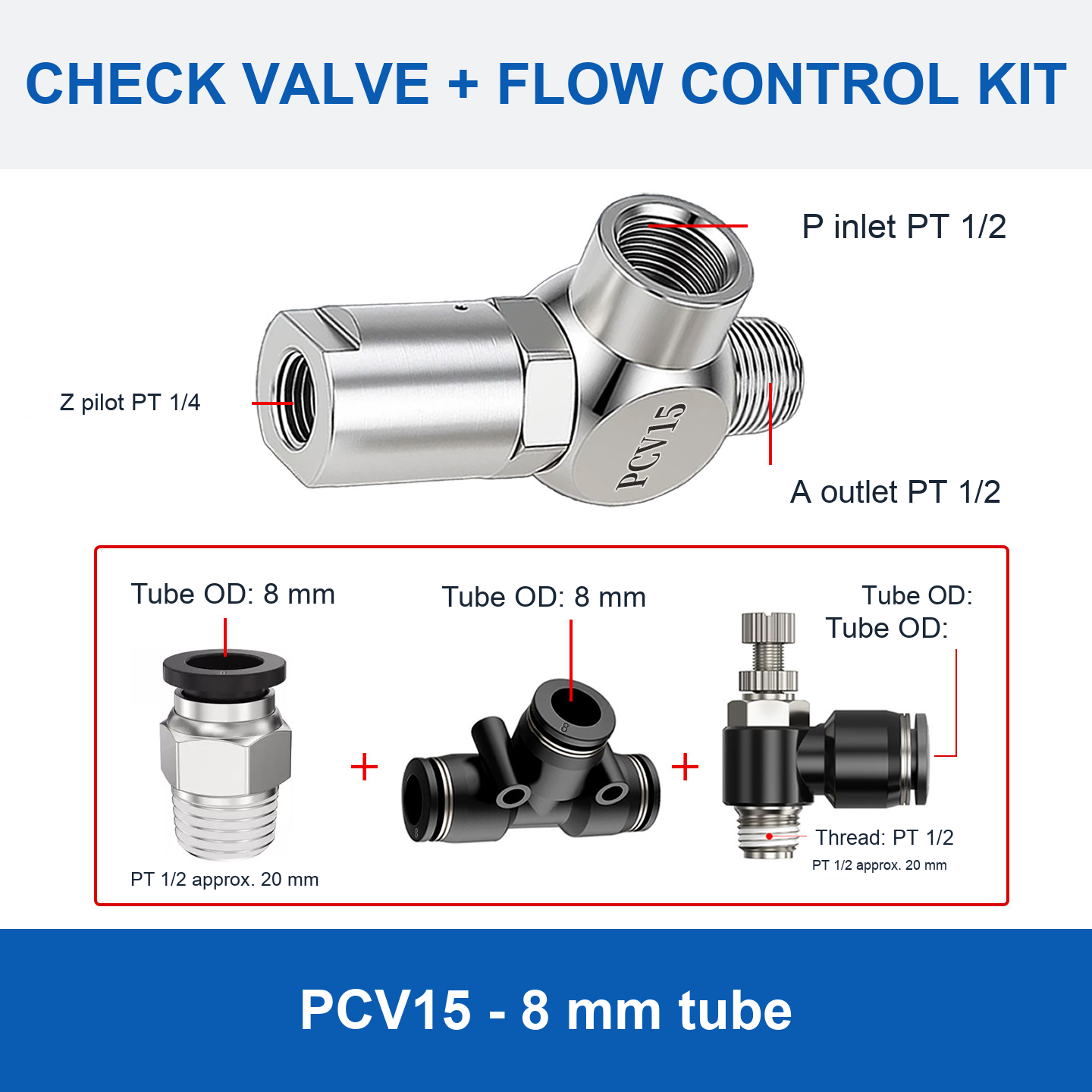
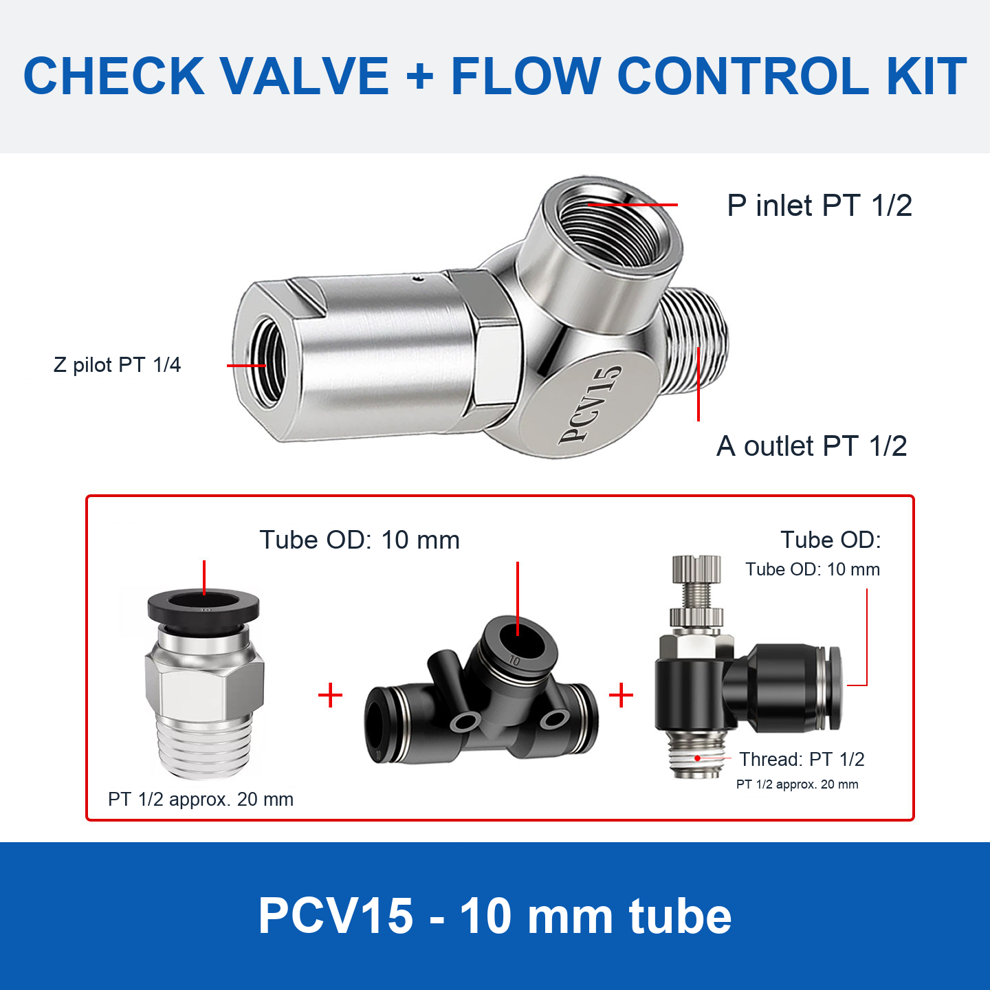
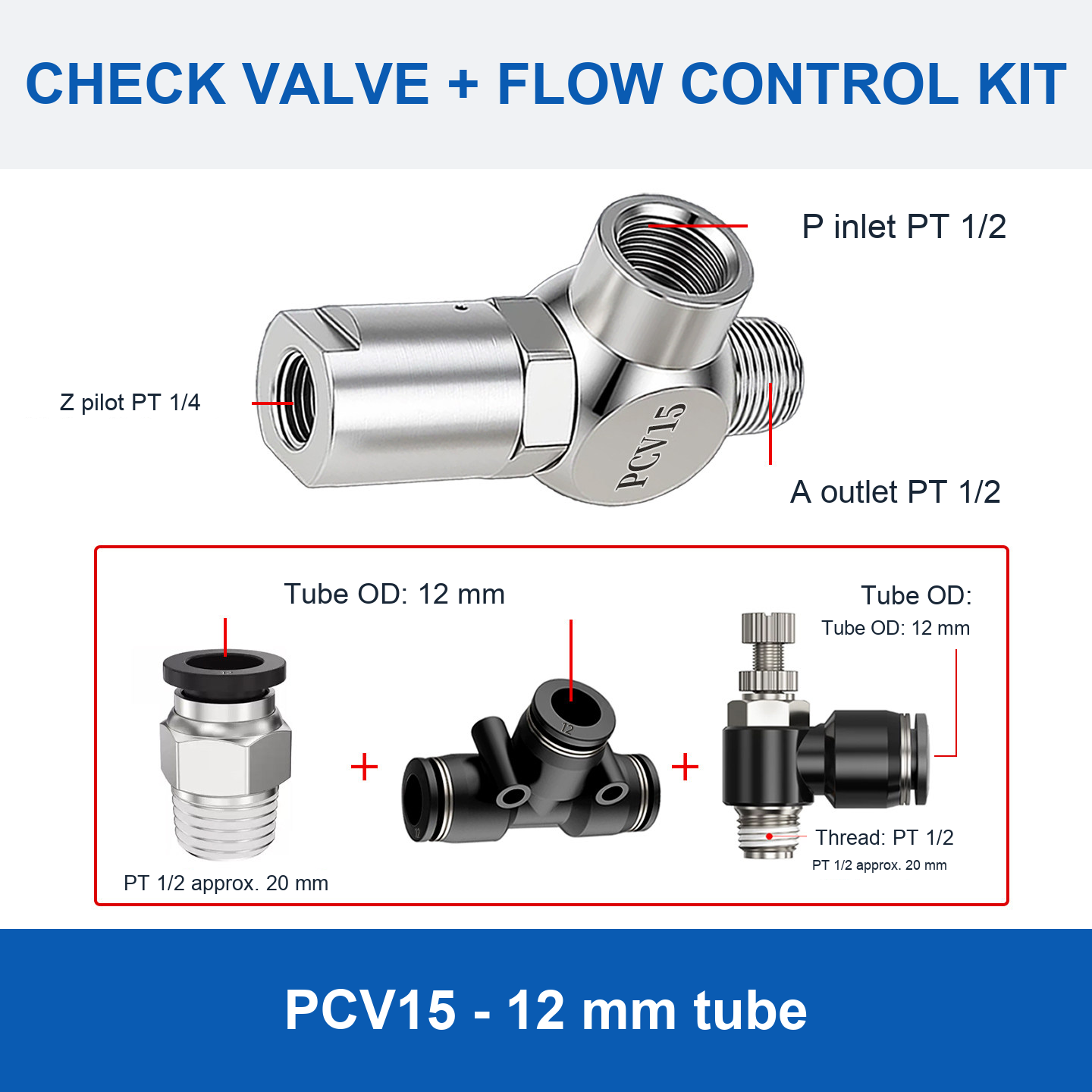
- Options ending in “mm tube”: valve with the flow-control accessories shown, including a push-in connector, tee fitting and flow-control fitting.
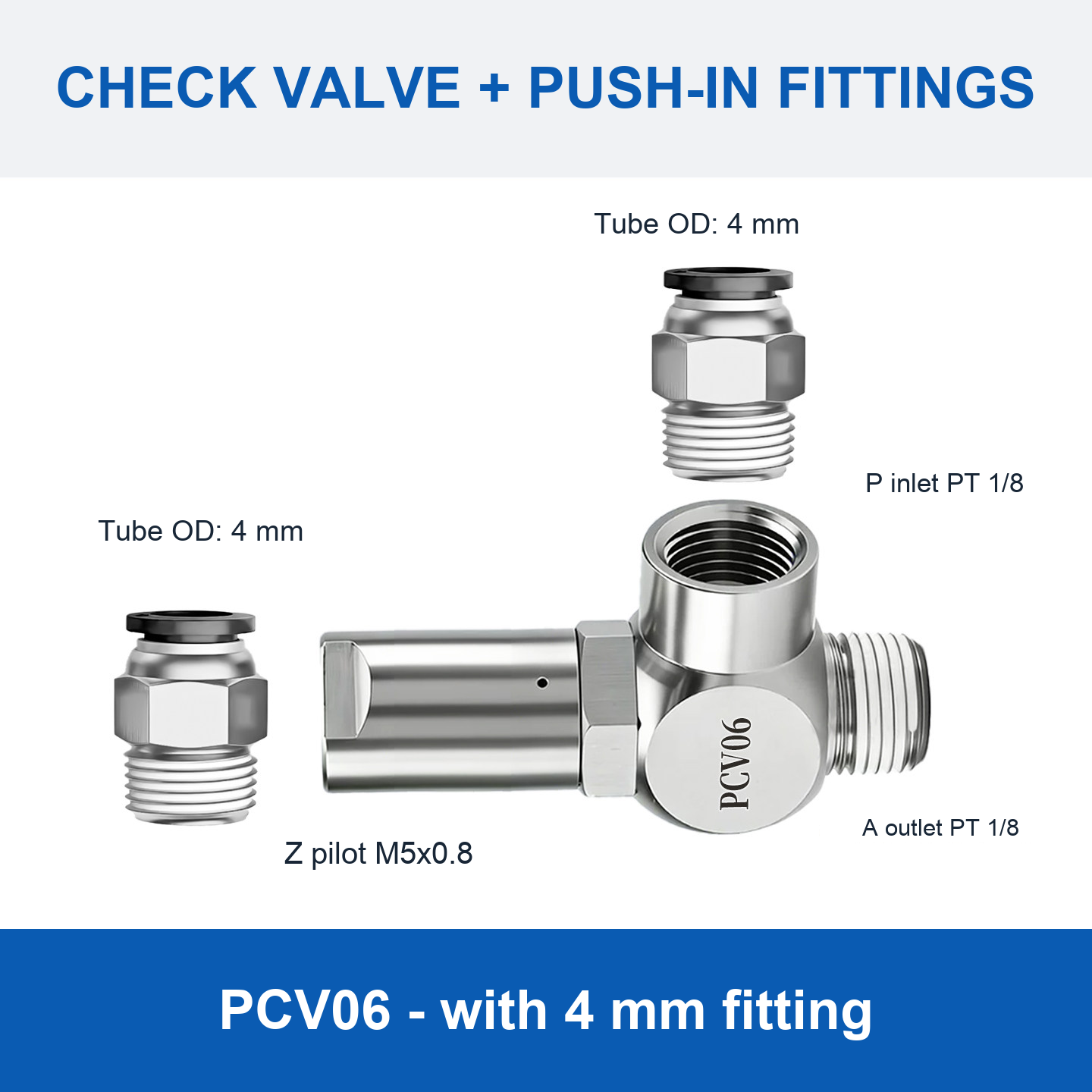
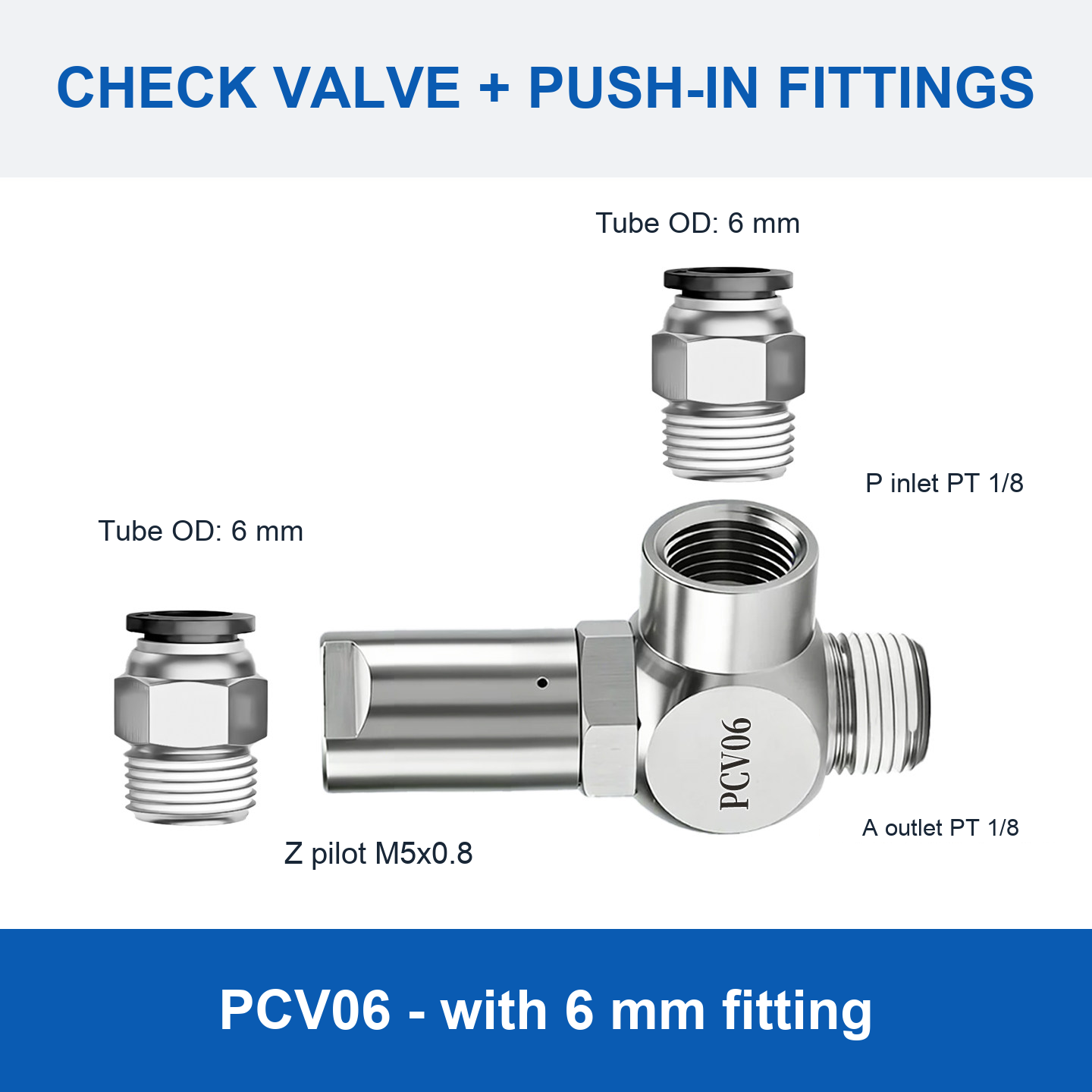
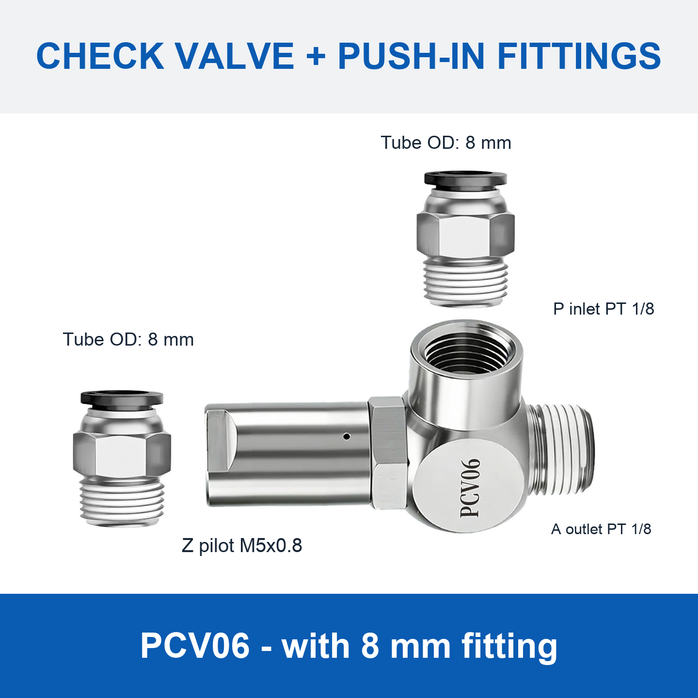
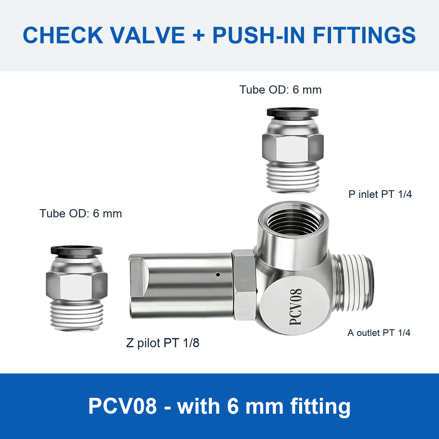
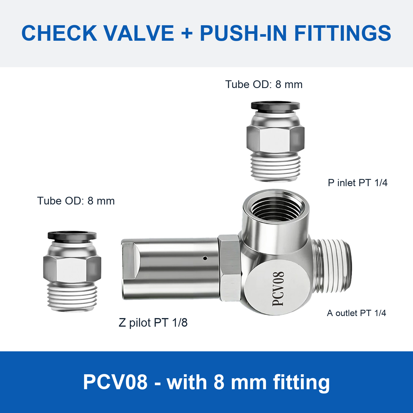
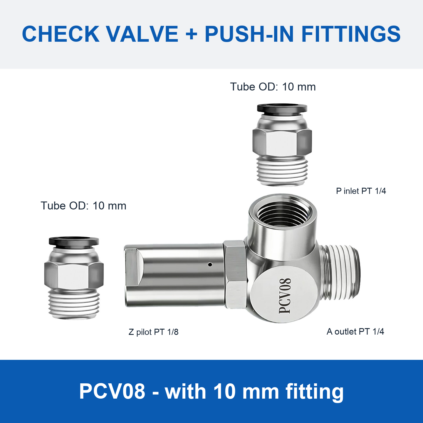
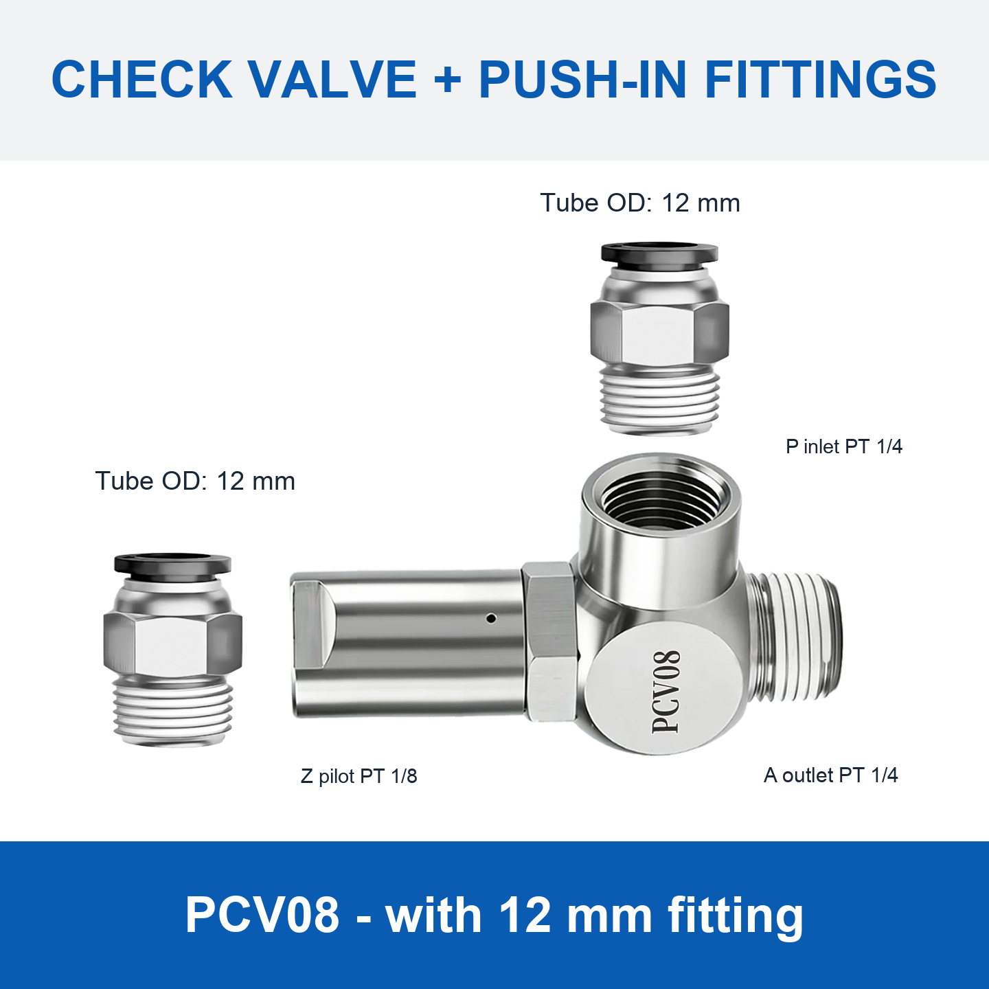
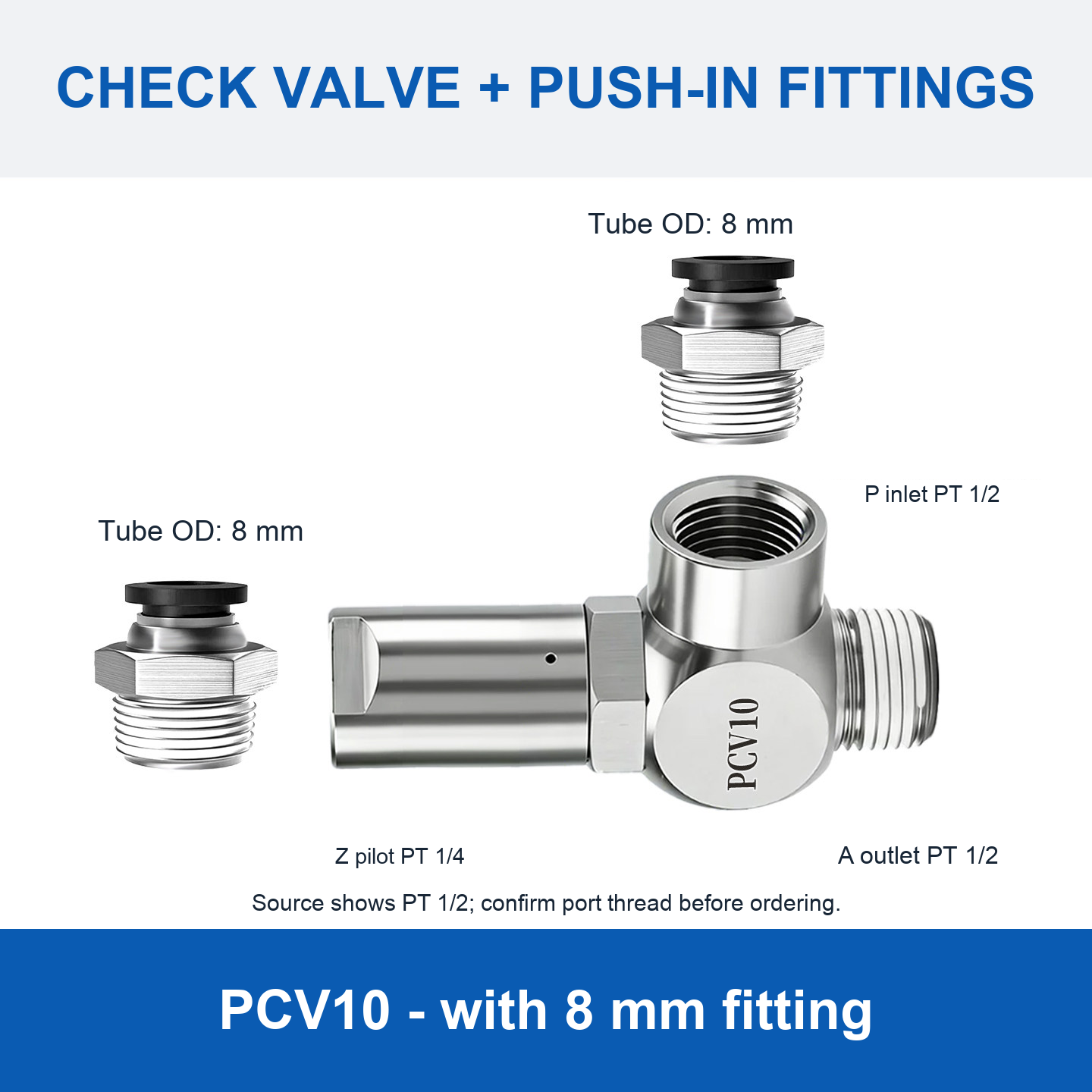
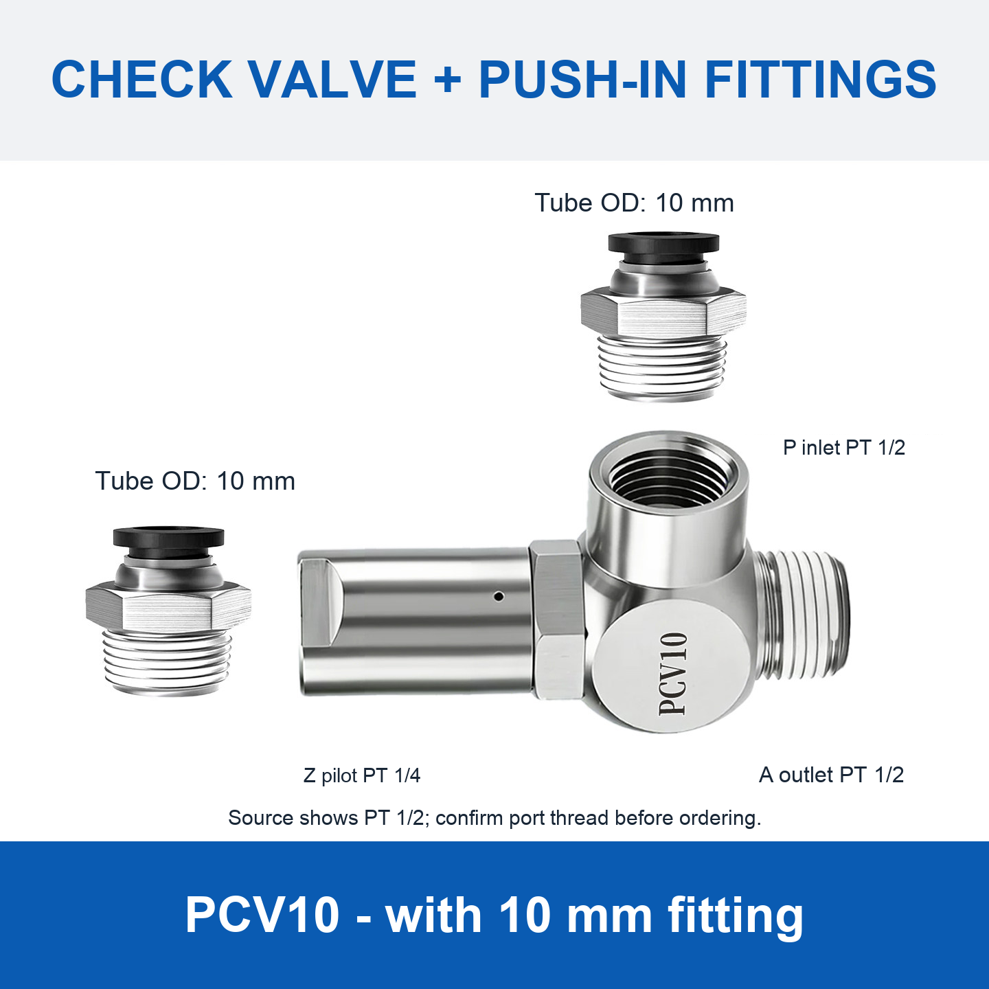
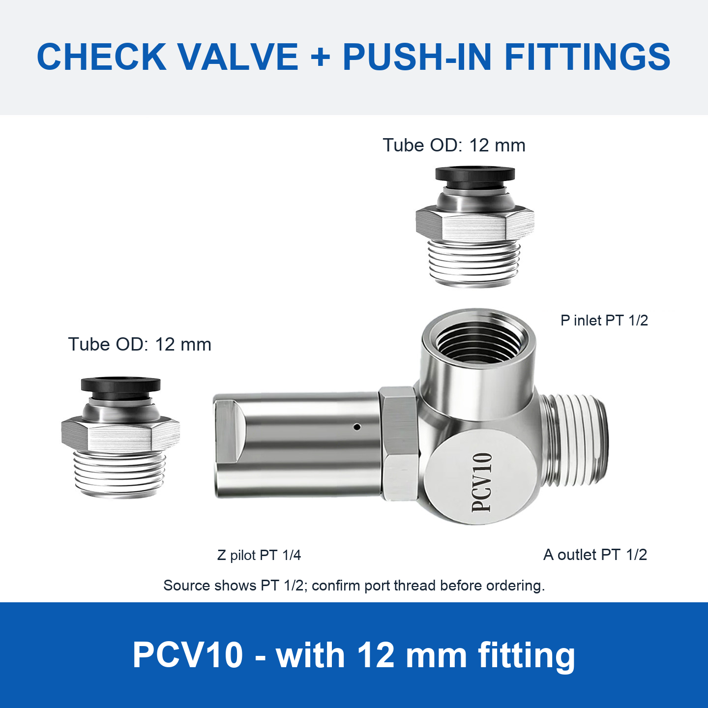
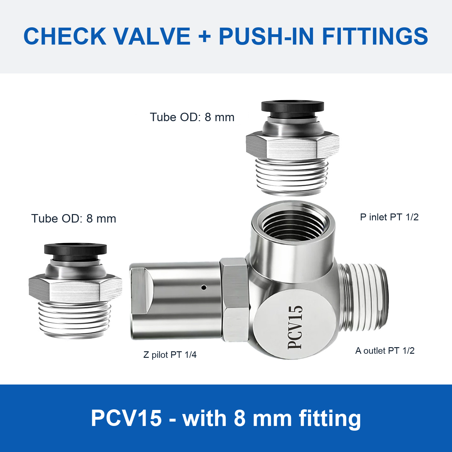
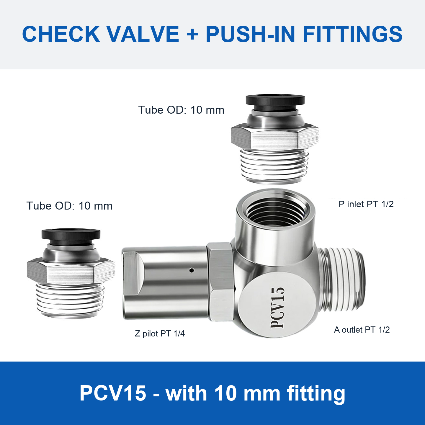
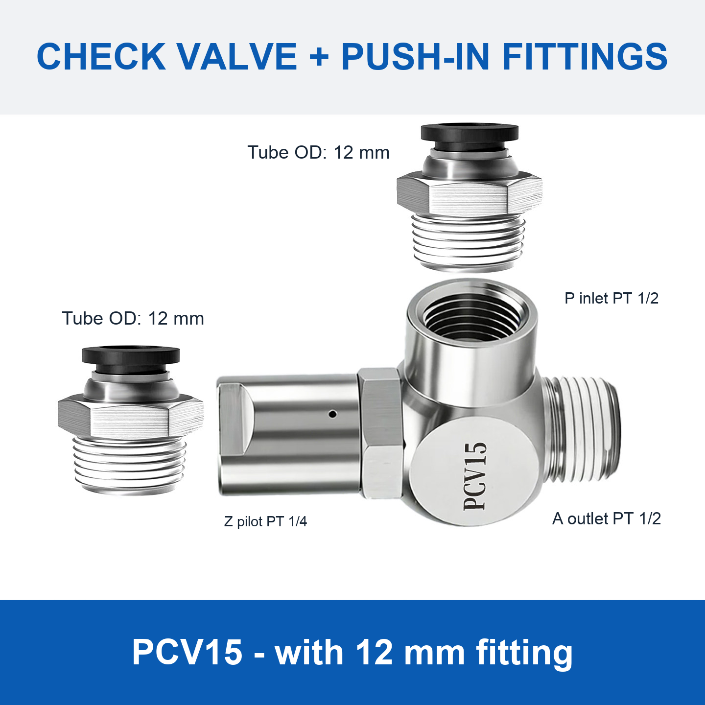
- Options marked “with … mm fitting”: valve with the push-in fittings shown.
- SKU-suffixed options: separate supplier-listed versions. These are not the plain PCV options. Exact product photographs are unavailable, so model reference cards are shown. Confirm the required version, manufacturer and specifications before ordering.
Tube sizes refer to tube outside diameter: PCV06 kits are offered for 4, 6 and 8 mm tubing; PCV08 for 6, 8, 10 and 12 mm; PCV10 and PCV15 for 8, 10 and 12 mm.
Base Valve Reference
| Model | P inlet / A outlet | Z pilot port | Marked length | Operating frequency |
|---|---|---|---|---|
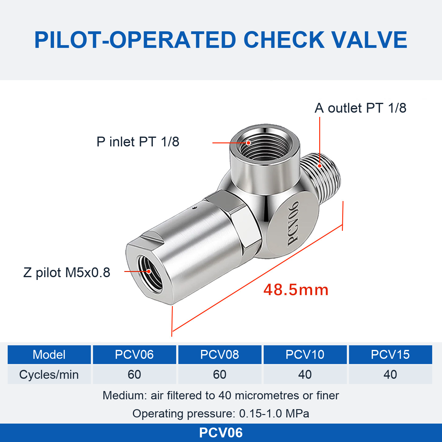
| PCV06 | PT 1/8 | M5 × 0.8 | 48.5 mm | 60 cycles/min |
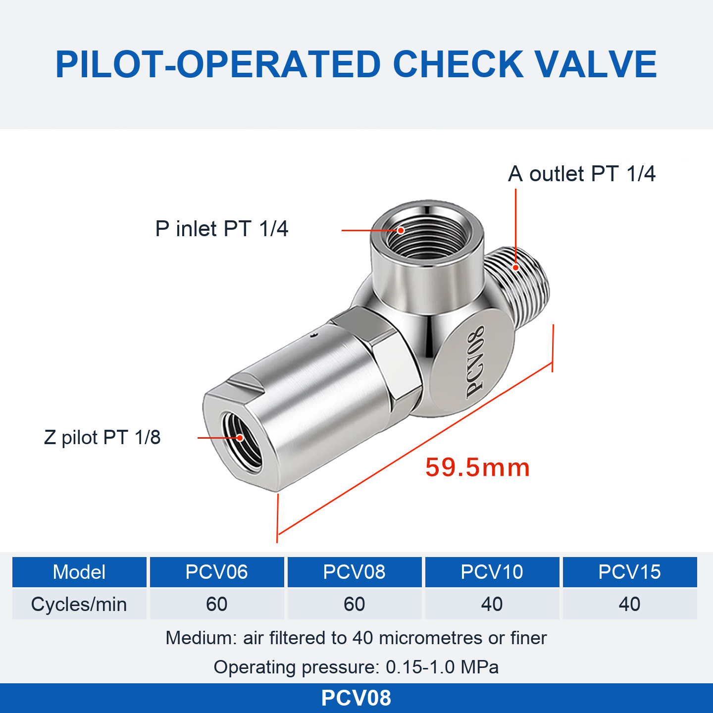
| PCV08 | PT 1/4 | PT 1/8 | 59.5 mm | 60 cycles/min |
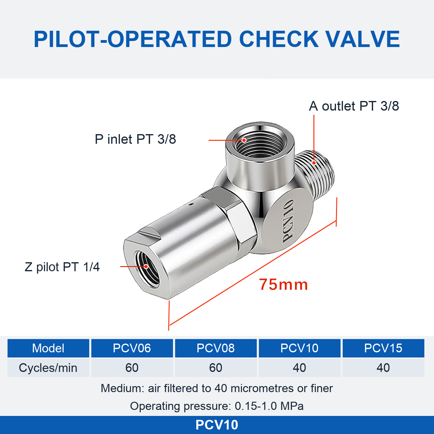
| PCV10 | PT 3/8 | PT 1/4 | 75 mm | 40 cycles/min |
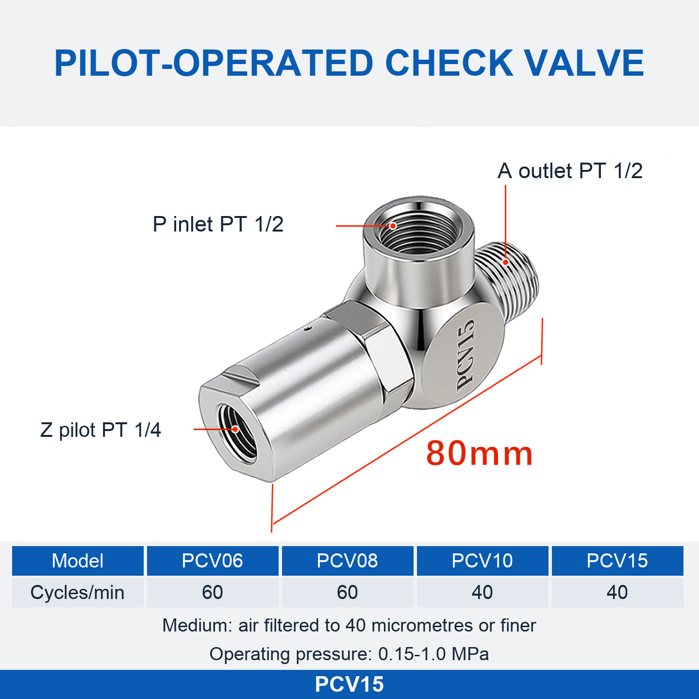
| PCV15 | PT 1/2 | PT 1/4 | 80 mm | 40 cycles/min |
The base-valve diagrams specify an operating pressure of 0.15–1.0 MPa and air filtered to 40 micrometres or finer. Lengths are the dimensions marked in the corresponding drawings. The product attributes identify a copper-based body material; a specific alloy grade is not provided. These reference values do not establish the ratings of every accessory or SKU-suffixed version.
Important Connection Notes
PCV10 push-in fitting kits: their supplied images mark the P and A ports as PT 1/2, while the PCV10 base-valve and flow-control kit drawings mark PT 3/8. This discrepancy is unresolved. Confirm the actual port thread for the selected SKU before ordering; do not choose solely by the illustration.
PCV15 flow-control kits: the supplied image labels the straight accessory fitting PT 1/2 but marks the valve pilot port PT 1/4. Confirm fitting compatibility and the intended connection before ordering.
Thread-diameter approximations printed beside accessory fittings are reference markings, not tube sizes or guaranteed measured dimensions. Check the selected model, kit contents, tube OD, port threads and flow direction before installation. No unsupported temperature, flow-rate or certification claims are made.
PCV Pilot-Operated Check Valves
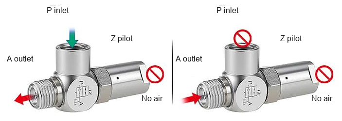
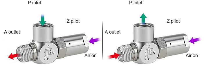
Nickel-plated brass valves for pneumatic pressure-holding circuits and cylinder stopping or positioning. A pilot signal releases the check function to allow reverse flow. Select the exact valve and fitting configuration using the product options above.
Nickel-Plated Brass Body
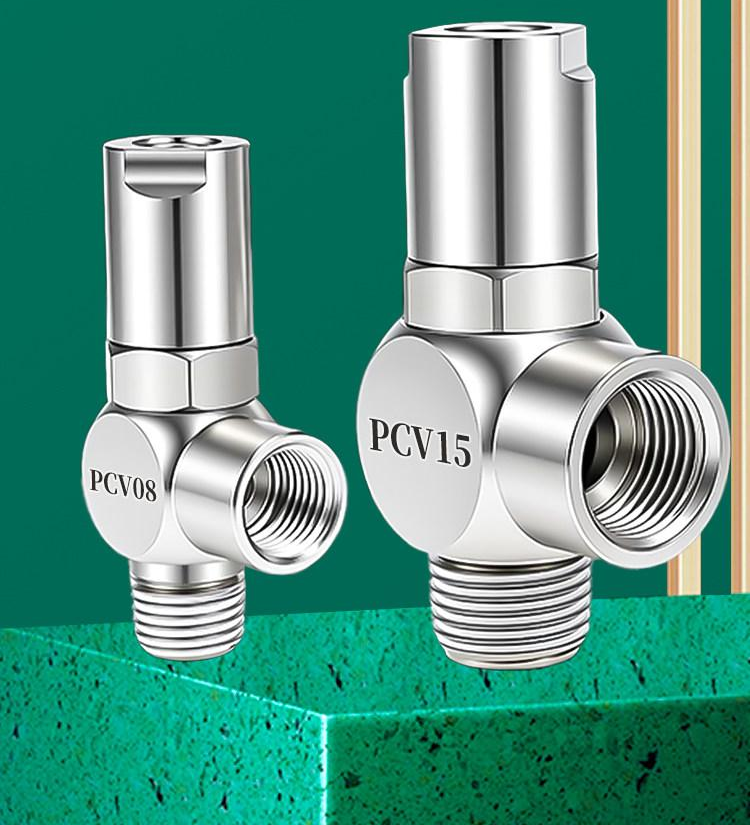
The source describes a nickel-plated brass body, threaded connections and a rigid construction intended for resistance to wear and impact. Sealing and suitability depend on the complete installation and operating conditions.
Connection Configurations
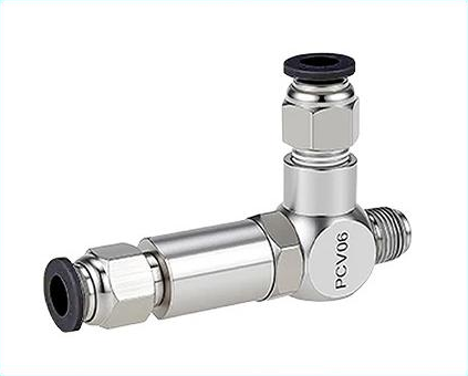
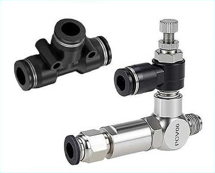
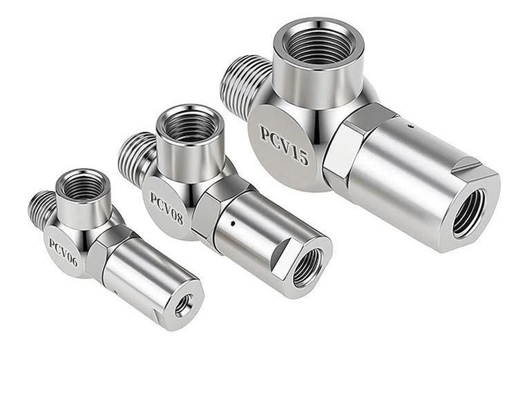
Photos illustrate configurations, not a promise that every pictured accessory is included with every option. Refer to the selected model and the configuration notes above.
Operating Principle
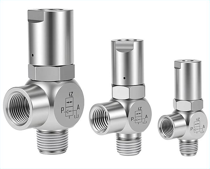
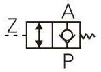
Port identification: P = inlet; A = outlet; Z = pilot port.
Installation Reference
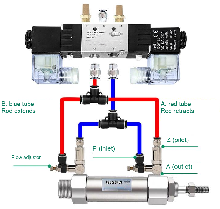
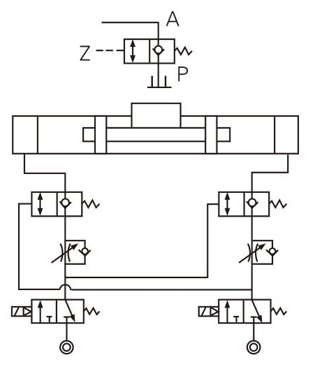
The source illustrates a 4V210-08 solenoid-valve circuit for load-holding applications and a 4V230E-08 exhaust-center circuit for intermediate cylinder stopping. These are application references, not a certified fall-prevention or personnel-safety system. Have the complete pneumatic circuit and load risks assessed before use.
Ordering-Code Reference
PCV + main-port code + pilot-connection code + thread code. The source lists the following naming rules. This reference does not add G-thread, NPT-thread or push-in variants to the current sale options.
| Code field | Source definition |
|---|---|
| Series | PCV — pilot-operated check valve |
| Main-port code | 06 = 1/8 in; 08 = 1/4 in; 10 = 3/8 in; 15 = 1/2 in |
| Pilot-connection code | Blank = female thread; F = push-in tube connection |
| Thread code | Blank = PT; G = G thread; T = NPT thread |
| Pilot type | Pilot connection size | Corresponding main-port size |
|---|---|---|
| Female thread (blank) | M5 × 0.8 | 1/8 in |
| Female thread (blank) | 1/8 in | 1/4 in |
| Female thread (blank) | 1/4 in | 3/8 in or 1/2 in |
| Push-in (F) | Ø6 mm tube | 1/8 in or 1/4 in |
| Push-in (F) | Ø8 mm tube | 3/8 in or 1/2 in |
Pneumatic Symbol
Source Specifications
| Parameter | PCV06 | PCV08 | PCV10 | PCV15 |
|---|---|---|---|---|
| Working medium | Air, filtered to 40 µm or finer | Same | Same | Same |
| Operating pressure | 0.15–1.0 MPa | 0.15–1.0 MPa | 0.15–1.0 MPa | 0.15–1.0 MPa |
| Proof pressure | 1.5 MPa | 1.5 MPa | 1.5 MPa | 1.5 MPa |
| Temperature | −20 to 70 °C | −20 to 70 °C | −20 to 70 °C | −20 to 70 °C |
| Operating frequency | 60 cycles/min | 60 cycles/min | 40 cycles/min | 40 cycles/min |
| Main port | PT1/8 | PT1/4 | PT3/8 | PT1/2 |
| Pilot port | M5 × 0.8 | 1/8 in | 1/4 in | 1/4 in |
Proof pressure is a test rating, not the continuous working pressure. The table describes the source base-valve specifications. Where kit-image labels differ from these base-valve ports, the existing model-specific discrepancy notes above still apply; confirm the actual fitting before installation.
Applications and Features
Intended for pressure-holding circuits, cylinder stopping/positioning and application-specific pneumatic circuits. The push-in pilot option is described as saving installation space and simplifying connection. Operating performance depends on pressure, leakage, load and circuit design.
Internal Structure and Component Materials
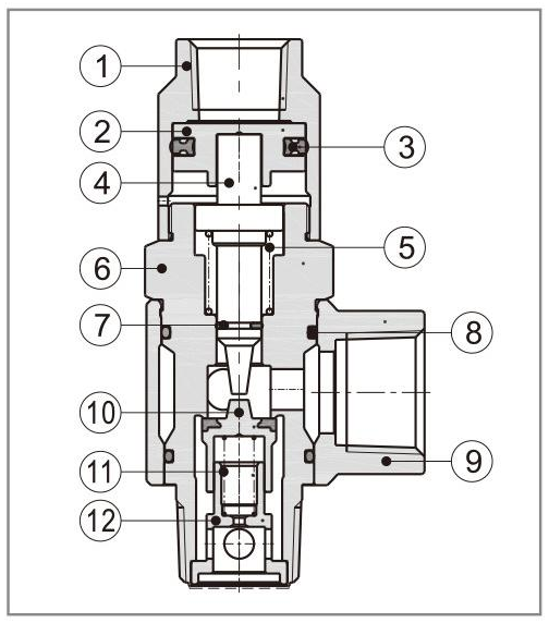
| No. | Component | Material |
|---|---|---|
| 1 | Pilot body | Aluminum alloy |
| 2 | Piston | Aluminum alloy |
| 3 | Profiled O-ring | NBR |
| 4 | Valve stem / spool | Brass or free-cutting steel |
| 5 | Spring | SUS304 |
| 6 | Body | Brass |
| 7 | Stem O-ring | NBR |
| 8 | O-ring | NBR |
| 9 | Adapter fitting | Aluminum alloy |
| 10 | Plug | Aluminum alloy + NBR |
| 11 | Spring | SUS304 |
| 12 | Base | Aluminum alloy |
Flow Characteristics
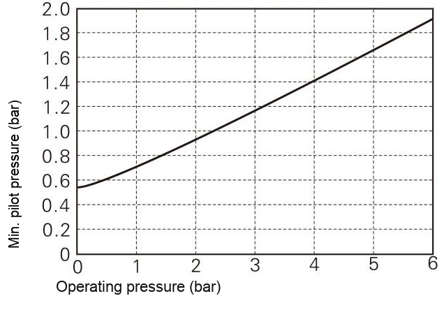
Minimum Pilot Pressure
Typical Cylinder Positioning Circuit
Product Photographs